Gas Metal Arc Brazing and Welding of Advanced High Strength Steels
|
|
|
- Silvia Merritt
- 5 years ago
- Views:
Transcription

1 Gas Metal Arc Brazing and Welding of Advanced High Strength Steels Mike Palko Ford Motor Company GDIS2018
2 A/SP Team Members Min Kuo, ArcelorMittal Tom Natale, AK Steel Corporation Stephen Tate, AK Steel Corporation Hassan Ghassemi, ArcelorMittal Elliot Biro, ArcelorMittal Amanda Davis, FiatChryslerAmerica US LLC Patrick Marchena, Ford Motor Company Mike Palko, Ford Motor Company Ted Coon, Ford Motor Company Richard Carlson, General Motors Weiping Sun, Nucor Corporation Justin Hunt, AET Integration Inc. Daniel L. Galiher, Tower International Vaidyanath B. Rajan, Lincoln Electric Michael White, Auto/Steel Partnership 3
3 Objective Evaluate the effects of gas metal arc welding (GMAW) and gas metal arc brazing (GMAB) on AHSS and UHSS and to identify the impact of welding and brazing on joint strength. 4
4 Test Matrix Grade BH210 Thickness (mm) 0.67 Coating Process Filler HDGI BH HDGI DP HDGA GMAW GMAB GMAW GMAB GMAW GMAB ER70S-6 ERCuSi-A ER70S-6 ERCuSi-A ER70S-6 ERCuSi-A Materials less than 0.7 mm thick were tested with both ER70S-6 (GMAW) and ERCuSi-A silicon bronze (GMAB) filler metals 5
5 Test Matrix (Cont d) 6 Grade Thickness (mm) Coating Process Filler GMAW ER70S-6 DP HDGI GMAW ER80S-D2 GMAW ER100S-G GMAW ER70S-6 CP HDGI GMAW ER80S-D2 GMAW ER100S-G GMAW ER70S-6 780SF 2.7 uncoated GMAW ER80S-D2 GMAW ER100S-G DP uncoated GMAW ER70S-6 GMAW ER100S-G DP EG GMAW ER70S-6 GMAW ER100S-G DP HDGA GMAW ER70S-6 MS uncoated GMAW ER70S-6 MP uncoated GMAW ER70S-6 HSLA uncoated GMAW ER70S-6 Selected materials were tested with three different strength of filler metals: ER70S-6 (70 ksi) ER80S-D2 (80 ksi) ER100S-G (100 ksi)
6 Welding Setup Sheets sheared to 6 x 12 were robotically welded in 1F position 0.1 mm shims used on faying surfaces of sheet steels diameter wire 90% Argon 10% CO 2 shielding gas (GMAW) 100% Argon shielding gas (GMAB) 7
7 Test Methods X-ray inspection (referencing ISO and ISO 5817) for joints made with zinc coated steels porosity percentage was measured Cross-section examination Microhardness traverse Quasi-static shear tension 8

8 Specimen Preparation Test specimens were waterjet cut from continuous welded panels in order to eliminate the effects of weld starts and stops Example photo provided by A/SP 9

9 Welding Parameters Grade Thickness (mm) Coating Process Filler Current (A) Voltage (V) Travel Speed (in/min) 0.9t<L1<1.1t BH HDGI GMAW ER70S GMAB ERCuSi-A BH HDGI GMAW ER70S GMAB ERCuSi-A DP HDGA GMAW ER70S GMAB ERCuSi-A GMAW ER70S DP HDGI GMAW ER80S-D GMAW ER100S-G GMAW ER70S CP HDGI GMAW ER80S-D GMAW ER100S-G GMAW ER70S SF 2.7 uncoated GMAW ER80S-D GMAW ER100S-G DP uncoated GMAW ER70S GMAW ER100S-G DP EG GMAW ER70S GMAW ER100S-G DP HDGA GMAW ER70S MS uncoated GMAW ER70S MP uncoated GMAW ER70S HSLA uncoated GMAW ER70S t<L2<2.5t Welding parameters were developed to obtain the targeted weld size

10 Weld and Braze Size Grade Thickness (mm) Coating Process Filler Leg Length L1 (mm) Leg Length L2 (mm) Penetration (mm) Convexity (mm) Toe Angle (degrees) BH HDGI GMAW ER70S GMAB ERCuSi-A BH HDGI GMAW ER70S GMAB ERCuSi-A DP HDGA GMAW ER70S GMAB ERCuSi-A GMAW ER70S DP HDGI GMAW ER80S-D GMAW ER100S-G GMAW ER70S CP HDGI GMAW ER80S-D GMAW ER100S-G GMAW ER70S SF 2.7 uncoated GMAW ER80S-D GMAW ER100S-G DP uncoated GMAW ER70S GMAW ER100S-G DP EG GMAW ER70S GMAW ER100S-G DP HDGA GMAW ER70S MS uncoated GMAW ER70S MP uncoated GMAW ER70S HSLA uncoated GMAW ER70S Average weld and braze size for each joint 11
11 X-ray Results: 0.67 mm BH210 HDGI ER70S-6 filler metal ERCuSi-A filler metal 12 Example specimen shown X-ray inspections were performed to detect imperfections in weld and braze metals


12 X-ray Results: GMAW 2.0 mm DP780 HDGI ER70S-6 filler metal ER80S-D2 filler metal ER100S-G filler metal Example specimen shown 13 Porosity percentage values are tabulated in the report


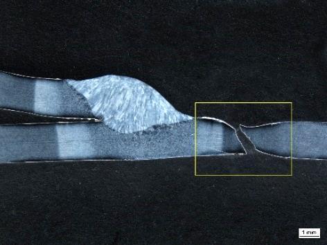
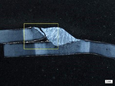
13 Cross-sections: 0.67 BH210 HDGI Joints ER70S-6 filler metal ERCuSi-A filler metal 14

 12.")
14 Microhardness Traverse vs. Fracture Location 0.67 mm BH210 HDGI ER70S-6 weld ERCuSi-A braze Microhardness Traverse Average Peak Load and (Joint Efficiency) kn (100%) kn (101%) Typical Fracture Location 15 heat-affected zone base metal


15 Cross-sections: 2.0 mm DP780 HDGI Joints ER70S-6 filler metal ER80S-D2 filler metal ER100S-G filler metal 16
 2.")

 76.")
16 Microhardness Traverse vs. Fracture Location (Cont d) 2.0 mm DP780 HDGI ER70S-6 weld ER80S-D2 weld ER100S-G weld Microhardness Traverse Average Peak Load and Joint Efficiency 73.4 kn (91%) 71.9 kn (89%) 76.0 kn (94%) Typical Fracture Location 17 weld metal weld metal heat-affected zone


17 Fracture Location: 2.0 mm DP780 HDGI ER70S-6 filler metal ER80S-D2 filler metal ER100S-G filler metal weld metal weld metal heat-affected zone 18
18 Summary of Test Results Grade Thickness (mm) Coating Process Filler Basemetal Microhardness (HV500g) Minimum Microhardness (HV500g) Minimum Microhardness Location Joint Peak Load (kn) Nominal Joint Strength (MPa) Joint Efficiency (%) Percent Porosity (X-ray) Fracture Location BH HDGI GMAW ER70S base metal heat-affected zone GMAB ERCuSi-A base metal base metal BH HDGI GMAW ER70S base metal heat-affected zone GMAB ERCuSi-A base metal base metal DP HDGA GMAW ER70S base metal heat-affected zone GMAB ERCuSi-A braze braze GMAW ER70S heat-affected zone weld metal DP HDGI GMAW ER80S-D heat-affected zone weld metal GMAW ER100S-G heat-affected zone heat-affected zone GMAW ER70S heat-affected zone weld metal CP HDGI GMAW ER80S-D heat-affected zone weld metal GMAW ER100S-G heat-affected zone near fusion line GMAW ER70S heat-affected zone n/a near fusion line 780SF 2.7 uncoated GMAW ER80S-D heat-affected zone n/a heat-affected zone GMAW ER100S-G heat-affected zone n/a heat-affected zone DP uncoated GMAW ER70S heat-affected zone n/a weld metal GMAW ER100S-G heat-affected zone n/a heat-affected zone DP EG GMAW ER70S weld weld metal GMAW ER100S-G heat-affected zone n/a heat-affected zone DP HDGA GMAW ER70S heat-affected zone weld metal MS uncoated GMAW ER70S heat-affected zone n/a heat-affected zone MP uncoated GMAW ER70S heat-affected zone n/a weld metal HSLA uncoated GMAW ER70S heat-affected zone n/a near fusion line 19
19 Conclusions Quality welded and brazed joints were achieved for all test materials. A targeted gap of 0.1 mm between faying surfaces was effective in providing a consistent gap and at minimizing porosity in weld metal for coated materials. Fracture locations can be in the base metal, HAZ, weld metal, or near the weld fusion line, depending on material grade and thickness. For the thin gauge coated steels tested, GMAW and GMAB resulted in similar joint strength. Compared to ER70S-6 filler metal, ER100S-G appears to slightly increase the joint strength for the CP780, DP780, and DP1180 materials tested. Joint efficiency ranged from 40% (MS1700 Uncoated GMAW) to 105% (BH240 HDGI GMAB) and generally decreased as steel strength increased. The test methods used in this study may be used as a basis for developing gas metal arc welding and gas metal arc brazing qualification procedures. 20
20 For More Information Mike Palko Ford Motor Company Min Kuo ArcelorMittal Michael A. White Auto/Steel Partnership