Hiroshi Harada and Yuefeng GU
|
|
|
- Virgil Booker
- 5 years ago
- Views:
Transcription
1 High Temperature Materials Researches for Gas Turbines and Aeroengines at NIMS Hiroshi Harada and Yuefeng GU National Institute for Materials Science, Japan
2 High Temperature Materials Researches for Gas Turbines and Aeroengines at NIMS Hiroshi Harada and Yuefeng GU National Institute for Materials Science, Japan
3 1. Background 2. NIMS Alloy Development SC, EQ.coating, Cast-and wrought 3. Applications 4. Conclusions

4 Power supply and CO2 Emission in Japan (normal situation) Thermal 55% Nuclear 35% Thermal 55% Hydro 10% Power Supply CO2 Emission
5 Efficiency of Advanced Thermal Power Systems 1700 GT X 1/2 CO2 (Efficiency, fuel) Coal firing Steam Turbine
6 1. Background 2. NIMS Alloy Development SC, EQ.coating, Cast-and wrought New Alloys 3. Applications 4. Conclusions


7 1800 C Advanced C&W Alloys 1500 C 1300 C New Cr-base Alloys 1200 C New ODS Alloys 1150 C


8 A Flow of the Superalloy Development at NIMS NIMS / High Temperature Materials Unit Design/simulation 400kV TEM In-situ creep observation Process DS furnace Components Gas turbine / Aeroengine Manufacturers SC blades Manufacturing /Integration Test piece HP Disk Microstructures Atomistic Properties Long-term creep, Fatigue, etc disks 3D Atom probe FIM Miniature test(tensile,creep,etc)

9 Inlet gas temperature Polycrystalline Directional solidified Single crystal 5 ~10 C/year Improved coating and cooling Improved materials Year

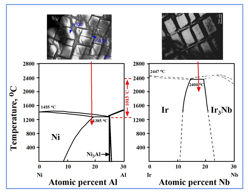
10 Pseudo-Binary Phase Diagram Ni+X Ni Ni3(Al,Y) precipitation hardening Ni-base superalloy Al+Y
11 Tie-line alloys of Inconel713C CC x15 Tie-line alloys of TMS-75, 82+ SC x600 Harada,et.al(NIMS),J.ISIJ,1979 Murakumo, et.al (NIMS), Acta.Mat,2004


12 Further strengthening by introducing finer interfacial dislocation network during creep at 3rd Gen. 4th Gen. 5th Gen. Higher Mo or Re (with Ru for phase stability), For creating larger negative lattice misfit, for finer dislocation networks to be accommodated.
13 NIMS Alloy Design Program A mathematical model composed of experimental equations derived from the NIMS superalloy database (Yokokawa,et.al.,Superalloys2004)
14 Alloy development at NIMS 1150 TMS-162 A realistic target for the next SC superalloy: 1150 C

15 Coating in equilibrium with substrate = EQ Coating γ phase, γ phase in the substrate are in thermodynamically equilibrium state chemical potential of each elements are equal γ, γ and γ/γ phase coatings are in equilibrium with substrate γ,γ, γ/γ phase coatings γ γ/γ structure in Superalloy γ


16 EQuilibrium coating trial on a new generation superalloy Conventional Coating EQ coating Amdry9954 As coat EQ coating TMBC-1 After 1100, 300h Application to TBC Diffusion Layer 90μm Diffusion Layer 40μm SRZ 140μm No SRZ! Kawagishi, et.al, (NIMS)
17 Temperature for 1000 h rupture life at 630 MPa Rene41 Powder Metallurgy In 718 Astrology Waspaloy In100 Rene 95 Rene95 U720LI Year Rene 88DT U720 N 18 RR C up Casting & Wrought ME 3 In718 Plus NIMS TMP Alloy (P/M ) NIMS TMW Alloy (C & W) 75 C up
18 Co-base superalloys (g-g ) Co NIMS Patented Co-Ti High Phase Stability Forging easily g-g (TMW Alloy) U720LI Ni-base superalloys (g-g ) High Strength Ti 1. Scripta Mat., 55(2006) Met. & Mat. Trans., 36(2005)2921


19 Triple Melting Ingot, 1.7ton VIM ESR VAR Upset and draw Billet, Φ200 x 3150mm Pancake, Φ440 mm Forge VIM Vacuum Induction Melting ESR Electroslag Remelting VAR Vacuum Arc Remelting


20 Uniform microstructure formed in the pancake (Mitsubishi Materials Co.) 440 mm 8~15μm

21 TMW alloys: Improved temperature capability in 0.2% creep time Grain size: 8-15mm Other tensile, fatigue, crack growth properties are equivalent or better than U720Li Gu, et.al, NIMS
22 1. Background 2. NIMS Alloy Development SC, EQ.coating, Cast-and wrought 3. Applications 4. Conclusions

23 Change after Japan Earthquake Nuclear 35% Hydro 10% Thermal 55% Nuclear power stations in Japan(53): Fukushima lost Onagawa emergency stopped Hamaoka stopped some others under inspections may take more time before operation Nuclear power supply in Japan 35% 15% LNG gas turbines and others to substitute the capability: MHI, KHI, IHI, Hitachi are in their full production for future Power Supply New national policy for energy is now discussed in the Government


24 Present status of the 4 th generation SC superalloy for application METI: Supersonic Engine Project 4th generation SC TMS-138 (NIMS/IHI Turbine inlet temperature 1650 Turbine blade made of TMS-138 Test turbine run at 1650
 Thermal efficiency : 56-60%")
25 MW LNG Combined Cycle Gas Turbine (MHI-NIMS) Thermal efficiency : 56-60% HHV


26 A wide use of superalloy components in various power engineering systems Large Gas Turbines 300MW Coal Conversion Fuel Cell/Gas Turbine Hybrid IGCC LNG Gas Turbines for Combines Cycle Gas Turbine Cogeneration Fuel Cell/Gas Turbine Cogeneration Pebble Bed Modular Reactor(PBMR) 20MKW Gas Turbines PFBC H2 Gas Turbine Generating more power with minimized CO2 emissions

27 Boeing787 An Efficient Airliner Flight Efficiency 20 up (Due in 2011 Efficient Engine GE Rolls Royce

28 Rolls-Royce Centre of Excellence for Aerospace Materials at NIMS Opened on 30 June, 2006
 Turbine")
29 Rolls-Royce Centre of Excellence for Aerospace Materials at NIMS Established on 30 June, 2006 Trent Engines Boeing787, A350XWB, etc; every 40 improvement in blade temperature capability provides 1% better efficiency, and 1million$ cut in fuel / plane Workscope -New SC Superalloys (TMS-XXX Alloys) Turbine Blades
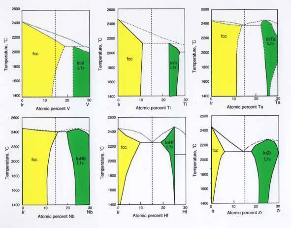
30 Possible Alternative Materials and Metallic Materials heir Outstanding Issues Nb-Silicide base alloys (Oxidation or Ductility) Mo-Silicide base alloys (Ductility) Cr-base alloys (Ductility) Co-base superalloys (Competition with Ni-base) Pt group metals base refractory superalloys (Cost, Density) Ceramics Si3N4 (Ductility) Melt Growth Composite (Ductility) CMC (Cost, Oxidation)
31 Conclusions 1. Ni-base SC superalloys have evolved to 5th generation(1100 ) and evolving further to the 6th generation(1150 ) alloys. 2. Coating systems are also being improved to match such high temperature use, not only the top coat but also the metallic bond coat materials, EQ coating. 3. Temperature capability of cast-and-wrought superalloys have been improved by based on U720Li, supporting the improved turbine blade technologies. 4. It will take some more time for possible alternative materials to be actually applied, especially for blade and disc materials. 5. Ni-base superalloys will be used for many more years, taking key roles for CO2 reduction in various power engineering.

32 From the members of High Temperature Materials 21 Project

33 TMF cycles to rupture Cycle (Cycle) Creep vs TMF properties of 4 th and 5 th Generation SC alloys 4 4 th gen. SC 2 2 nd Gen. SC Out-of-Phase, Strain: /-0.64% Tension at 400, Compression with 1h hold time at ,245MPa Further Improvement 5 5 th Gen. SC Creep rupture life (h)
34 Oxidation Resistance 0 Creep and Oxidation properties of 4 th and 5 th Generation SC alloys 2 nd Gen. Alloys TMS-19X Alloys 1000 Creep Strength Oxidation resistance: 1100, 1h cyclic Creep strength: 1000 /245MPa rapture life(h) ist generation, commercial 2nd generation, commercial 3rd generation, commercial 1st generation, NIMS 2nd generation, NIMS 3rd generation, NIMS 4th and 5th generation, NIMS 4th generation, oxidation reisitant, NIMS 5th generation, oxidation resistant, NIMS

35 Solid solution hardening: up to 6 wt% Re, etc. in SC TCP phase C C C T.C.P. (Topologically Close Packed) phases: (μ phase, σ phase, )
 by O Hara et. al.")
 4 th generation SC alloys ~1085 C")
36 PGMs additions for phase stabilisation Ru addition (1996) by O Hara et. al. (GE) Ir addition (1997) by Kobayashi et.al. (NIMS) 4 th generation SC alloys ~1085 C TCP free
37 TMS-75 (3rd generation) TMS-138,139 (4th generation) TMS-162,1XX Alloy development at NIMS Mo addition for strengthening Larger negative misfit Rafted structure and finer dislocation network. Ru/Ir addition for phase stability (5th Generation)
38
39
40 300 CMSX-4 (2nd SC) TMS-138 (4th SC) 200 Stress (MPa) MGA1400 (1st DS) D43 (Nb-10W-1Zr-0.1C) W-25Re Ta-7W-3Re Target 1750 o C DS Ir-15Nb-1Ni o C 675 o C Larson-Miller Parameter LMP = T(20 + log t) 10-3
41