9/29/2014 8:52 PM. Chapter 3. The structure of crystalline solids. Dr. Mohammad Abuhaiba, PE
|
|
|
- Lorena Alberta Sparks
- 5 years ago
- Views:
Transcription
1 1 Chapter 3 The structure of crystalline solids
2 2 Home Work Assignments HW 1 2, 7, 12, 17, 22, 29, 34, 39, 44, 48, 53, 58, 63 Due Sunday 12/10/2014 Quiz # 1 will be held on Monday 13/10/2014 at 11:00 am during the discussion lecture
3 3 Why study the structure of crystalline solids? Properties of some materials are directly related to their crystal structure. Significant property differences exist between crystalline and noncrystalline materials having the same composition.
4 4 Crystal structures Fundamental concepts Crystalline materials: Atoms or ions form a regular repetitive, grid-like pattern, in 3D A lattice: collection of points called lattice points, arranged in a periodic pattern so that the surroundings of each point in the lattice are identical.
5 5 Crystal structures Unit Cells Atoms arrange themselves into an ordered, 3d pattern called a crystal Unit cell: small repeating volume within a crystal Each cell has all geometric features found in the total crystal
6 6 Metallic crystal structures Lattice Parameter: describe size and shape of unit cell, includes: 1. dimensions of the sides of the unit cell 2. angles between the sides (F3.4)
7 7 Metallic crystal structures Face Centered Cubic (FCC) FCC: AL. Cu, Pb, Ag, Ni 4 atoms per unit cell Lattice parameter, a FCC Coordination Number (CN): # of atoms touching a particular atom, or # of nearest neighbors for that particular atom
8 8 Metallic crystal structures Face Centered Cubic (FCC) For FCC, CN =12 APF for FCC = 0.74 Metals typically have relatively large APF to max the shielding provided by the free electron cloud.
9 9 Metallic crystal structures Face Centered Cubic (FCC)
10 10 Metallic crystal structures Example problem 3.1 Calculate the volume of an FCC unit cell in terms of the atomic radius R.

11 11 Metallic crystal structures Example problem 3.2 Show that the atomic packing factor for the FCC crystal structure is 0.74.

12 12 Metallic crystal structures Body Centered Cubic (BCC) Figure atoms/unit cell Lattice parameter, a BCC CN = 8 APF = 0.68
 Lattice parameter c/a = 1.633 No of atoms = 6 F3.3 APF = 0.")
13 13 Metallic crystal structures Hexagonal Closed-Packed Structure (HCP) Lattice parameter c/a = No of atoms = 6 F3.3 APF = 0.74
14 Density computation Density (No. of atoms/cell)(atomic mass) (volume of unit cell)(n ) (atoms)(g/mole) (cm )(atoms/mole) g cm 3 3 A
15 Density computation Example problem 3.3 Theoretical Density Computation for Copper Copper has an atomic radius of nm, an FCC crystal structure, and an atomic weight of 63.5 g/mol. Compute its theoretical density and compare the answer with its measured density.
16 Polymorphism and Allotropy Polymorphism: Materials that can have more than one crystal structure. When found in pure elements the condition is termed Allotropy A volume change may accompany transformation during heating or cooling. This volume change may cause brittle ceramic materials to crack and fail.
17 Polymorphism and Allotropy Ex: zirconia (ZrO 2 ): At 25 o C is monoclinic At 1170 o C, monoclinic zirconia transforms into a tetragonal structure At 2370 o C, it transforms into a cubic form Ex: Fe has BCC at RT which changes to FCC at 912 C

18 Crystal systems 7 possible systems (T3.2) and (F3.4).

19 Crystallographic Point Coordinates Point
, locate the point")
20 Crystallographic Point Coordinates Example Problem 3.4 For the unit cell shown in the accompanying sketch (a), locate the point having coordinates

21 Crystallographic Point Coordinates Example Problem 3.5 Specify point coordinates for all atom positions for a BCC unit cell.
22 Crystallographic Directions Metals deform in directions along which atoms are in closest contact. Many properties are directional. Miller indices are used to define directions.
23 Crystallographic Directions Procedure of finding Miller indices: Using RH coordinate system, find coordinates of 2 points that lie along the direction Subtract tail from head Clear fractions Enclose the No s in [634], -ve sign (bar above No.) A direction and its ve are not identical A direction and its multiple are identical

24 24 Example Problem 3.6 Determine the indices for the direction shown in the accompanying figure.
25 25 Example Problem 3.7 Draw a unit cell direction within a cubic
26 Crystallographic Directions Families of directions Identical directions: any directional property will be identical in these directions. Ex: all parallel directions possess same indices. Sketch rays in the direction that pass through locations: 0,0,0, and 0,1,0 & ½,1,1 Directions in cubic crystals having same indices without regard to order or sign are equivalent
27 Crystallographic Directions Miller-Bravais indices for hexagonal unit cells Directions in HCP: 3-axis or 4-axis system. We must move in each direction to get from tail to head of direction, while for consistency still making sure that u + v = -t
28 Crystallographic Directions Miller-Bravais indices for hexagonal unit cells Conversion from 3 axis to 4 axis: u = 1/3(2u` - v`) v = 1/3(2v` - u`) t = -(u + v) w = w` u`, v`, w`: indices in the 3 axis system After conversion, clear fraction or reduce to lowest integer for the values of u, v, t, and w.
![29 3.9 Crystallographic Directions Example Problem 3.8 a) Convert [111] direction into the four-index system for hexagonal crystals.](/docs-images/87/96347869/images/29-0.jpg "b) Draw this direction within a reduced-scale coordinate system (per Figure 3.9).")
29 Crystallographic Directions Example Problem 3.8 a) Convert [111] direction into the four-index system for hexagonal crystals. b) Draw this direction within a reduced-scale coordinate system (per Figure 3.9). c) Now draw the [111] direction within a hexagonal unit cell that utilizes a three-axis (a 1, a 2, z) coordinate system.
 for the")
30 Crystallographic Directions Example Problem 3.9 Determine the directional indices (four-index system) for the direction shown.
31 Crystallographic planes Crystal contains planes of atoms that influence properties and behavior of a material. Metals deform along planes of atoms that are most tightly packed together. The surface energy of different faces of a crystal depends upon the particular crystallographic planes.
32 Crystallographic planes Calculation of planes Identify points at which plane intercepts x,y,z coordinates. If plane passes in origin of coordinates; system must be shifted. Take reciprocals of intercepts Clear fractions but do not reduce to lowest integer ( ).
33 Crystallographic planes Calculation of planes Notes: Planes and their ve are identical Planes and their multiple are not identical For cubic crystals, planes and directions having the same indices are perpendicular to one another

34 Crystallographic planes Example Problem 3.10 Determine the Miller indices for the plane shown in the figure.

35 Crystallographic planes Example Problem 3.11

36 Crystallographic planes Example Problem 3.12 Determine Miller Bravais indices for the plane shown in the hexagonal unit cell.
37 Crystallographic planes Atomic arrangements and Families of planes {} 2 or more planes may belong to same family of planes (all have the same planner density) In cubic system only, planes having same indices irrespective of order and sign are equivalent. Ex: in simple cubic Ex: {111} is a family of planes that has 8 planes.
38 Linear and Planar Densities Repeat distance: distance between lattice points along the direction Repeating distance between equivalent sites differs from direction to direction. Ex: in the [111] of a BCC metal, lattice site is repeated every 2R. Ex: repeating distance in [110] for a BCC is, but for FCC.
39 Linear and Planar Densities Linear density: No of atoms per unit length along the direction. Equivalent directions have identical LDs In general, LD = 1 / repeat distance Example: find linear density along [110] for FCC. LD = number of atoms centered on direction vector length of direction vector
40 Linear and Planar Densities Planar packing fraction: fraction of area of the area of a plane actually covered by atoms. In cubic systems, a direction that has the same indices as a plane is perpendicular to that plane. PD = number of atoms centered on a plane area of plane
41 Linear and Planar Densities Ex: How many atoms per mm 2 are there on the (100) and (111) planes of lead (FCC) LD & PD are important considerations relative to the process of slip. Slip is the mechanism by which metals plastically deform Slip occurs on the most closely packed planes along directions having greatest LD
42 Crystallographic planes Closed Packed Planes and directions Close packed planes are (0001) & (0002) named basal planes. An HCP unit cell is built up by stacking together CPPs in a ABABAB stacking sequence. Figure 3.15

43 Crystallographic planes Closed Packed Planes and directions Atoms in plane B (0002) fit into valleys between atoms on plane A (0001) The center atom in a basal plane is touched by 6 other atoms in the same plane, 3 atoms in a lower plane, and 3 atoms in an upper plane. Thus, CN of 12.
44 Crystallographic planes Closed Packed Planes and directions In FCC, CPPs are of the form {111} When parallel (111) planes are stacked: atoms in plane B fit over valleys in plane A atoms in plane C fit over valleys in both A and B the 4 th plane fits directly over atoms in A Therefore, a stacking sequence ABCABCABC is produced using the (111) plane CN = 12

45 Crystallographic planes Closed Packed Planes and directions Figure 3.16

46 Single Crystals Properties of single crystal materials depend upon chemical composition and specific directions within the crystal
47 Polycrystalline Materials Many properties of polycrystalline materials depend upon the physical and chemical char of both grains and grain boundaries.
48 Polycrystalline Materials Figure 3.18: Schematic diagrams of various stages in the solidification of a polycrystalline material; the square grids depict unit cells. a) Small crystallite nuclei b) Growth of crystallites; the obstruction of some grains that are adjacent to one another is also shown c) Upon completion of solidification, grains having irregular shapes have formed d) The grain structure as it would appear under the microscope; dark lines are the grain boundaries

49 Polycrystalline Materials Figure 3.18
50 Anisotropy Anisotropic material: properties depend on the crystallographic direction along which the property is measured Isentropic material: properties are identical in all directions Most polycrystalline materials will exhibit isotropic properties. Table 3.3
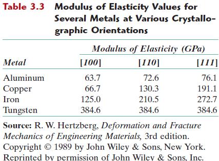
51 Anisotropy
52 X-Ray Diffraction: Determination of Crystal Structures X-rays Electromagnetic radiation Wavelengths between 0.1Å & 100Å Typically similar to inter-atomic distances in a crystal
53 X-Ray Diffraction: Determination of Crystal Structures X-ray diffraction is a tool used to: 1.Identify phases by comparison with data from known structures 2.Quantify changes in cell parameters, orientation, crystallite size and other structural parameters 3.Determine crystallographic structure (cell parameters, space group & atomic coordinates) of novel or unknown crystalline materials.
54 X-Rray diffraction: Determination of Crystal Structures - Bragg s law An X-ray incident upon a sample will either: 1. Be transmitted, in which case it will continue along its original direction 2. Be scattered by electrons of the atoms in the material. We are primarily interested in peaks formed when scattered X-rays constructively interfere.
55 X-Rray diffraction: Determination of Crystal Structures - Bragg s law Constructive Interference
56 X-Rray diffraction: Determination of Crystal Structures - Bragg s law Destructive Interference
57 X-Rray diffraction: Determination of Crystal Structures - Bragg s law When two parallel X-rays from a coherent source scatter from two adjacent planes their path difference must be an integer number of wavelengths for constructive interference to occur. Path difference = n λ = 2 d sin θ λ = 2 d hkl sin θ hkl
58 X-Rray diffraction: Determination of Crystal Structures - Bragg s law The angle between the transmitted and Bragg diffracted beams is always equal to 2θ as a consequence of the geometry of the Bragg condition. This angle is readily obtainable in experimental situations and hence the results of X-ray diffraction are frequently given in terms of 2θ.
59 X-Rray diffraction: Determination of Crystal Structures - Bragg s law The diffracting plane might not be parallel to the surface of the sample in which case the sample must be tilted to fulfill this condition.
60 X-RAY Diffraction: Determination of Crystal Structures - Inter-planar spacing Distance between adjacent parallel planes of atoms with the same Miller indices, d hkl. In cubic cells, it s given by d hkl a o h k l
61 61 Example calculate distance between adjacent (111) planes in gold which has a lattice constant of A.

62 X-RAY Diffraction: Determination of Crystal Structures - Powder diffraction A powder is a polycrystalline material in which there are all possible orientations of the crystals so that similar planes in different crystals will scatter in different directions.
63 X-RAY Diffraction: Determination of Crystal Structures - Powder diffraction In single crystal X-ray diffraction there is only one orientation. This means that for a given wavelength and sample setting relatively few reflections can be measured: possibly zero, one or two. As other crystals are added with slightly different orientations, several diffraction spots appear at the same 2θ value and spots start to appear at other values of 2θ.
64 X-RAY Diffraction: Determination of Crystal Structures - Powder diffraction Rings consisting of spots and then rings of even intensity are formed. A powder pattern consists of rings of even intensity from each accessible reflection at the 2θ angle defined by Bragg's Law.
65 X-RAY Diffraction: Determination of Crystal Structures - Powder diffraction Figure 3.21: Schematic diagram of an x-ray diffracto-meter T = x-ray source S = specimen C = detector O = axis around which specimen & detector rotate
66 X-RAY Diffraction: Determination of Crystal Structures - X-ray Diffractometer As the counter moves at constant angular velocity, a recorder automatically plots diffracted beam intensity as a function of 2q.
67 X-RAY Diffraction: Determination of Crystal Structures - X-ray Diffractometer Fig 3.22 shows a diffraction pattern for a powdered specimen. The high-intensity peaks result when Bragg diffraction condition is satisfied by some set of crystallographic planes. These peaks are plane-indexed in the figure
68 X-RAY Diffraction: Determination of Crystal Structures - X-ray Diffractometer The unit cell size and geometry may be resolved from the angular positions of the diffraction peaks Arrangement of atoms within the unit cell is associated with the relative intensities of these peaks.
69 X-RAY Diffraction: Determination of Crystal Structures Indexing Diffraction Pattern λ = 2 d sin θ d hkl a o h k l 2 2 2
70 70 Example Problem 3.13 For BCC iron, compute a. the inter-planar spacing b. the diffraction angle for the (220) set of planes. The lattice parameter for Fe is nm. Also, assume that monochromatic radiation having a wavelength of nm is used, and the order of reflection is 1.