A Controlled Sintering Process for More Permeable Ceramic Hollow Fibre Membranes
|
|
|
- Clarence Shepherd
- 5 years ago
- Views:
Transcription
1 A Controlled Sintering Process for More Permeable Ceramic Hollow Fibre Membranes Zhentao Wu, Rami Faiz, Tao Li, Benjamin F.K. Kingsbury, K. Li * Department of Chemical Engineering, Imperial College London, SW7 2AZ, UK Abstract In this study, a new controlled sintering process has been proposed to improve the water permeation of asymmetric alumina hollow fibre membranes. In this process, polymer binder (PESf) in precursor fibres is purposely pre-treated in static air at selected temperatures ( C) to have it partially removed, prior to be converted into carbon in a second sintering step (1450 C) under an oxygen free environment. During the second sintering step, proper bounding between ceramic particles takes place, while the growth of ceramic grains is effectively suppressed due to the presence of carbon. The carbon in the voids formed by particle packing also acts as a pore structure stabiliser and can be removed easily via subsequent thermal treatment in static air at 800 C. Compared to the membranes with the same asymmetric structure and sintered in static air only (i.e. normal sintering), the membranes sintered using the new controlled sintering process shows water permeation flux is approximately 13 times higher, together with comparable mechanical strength. Moreover, this original concept of using the polymer binder to design the pore structure of ceramic membranes can be transferred to other inorganic materials. Key words: Controlled sintering, water permeation, ceramic hollow fibre membrane, asymmetric structure * To whom the correspondence should be addressed. Tel: Fax: address: Kang.Li@imperial.ac.uk 1
2 1. Introduction A phase inversion assisted process involving viscous fingering phenomenon and sintering has been recently well investigated in fabricating inorganic hollow fibre membranes for various applications [1-6]. In contrast to other processes in fabricating ceramic micro-tubes of similar sizes, the unique difference lies in its flexibility in forming radial micro-channels, leading to a number of new asymmetric membrane structures that can hardly be achieved in a single-step via conventional fabrication techniques. In such a membrane fabrication process, generally a uniform mixture/suspension of ceramic particles, solvent, polymer binder and additives is extruded through a tubein-orifice spinneret, before entering an external coagulation bath (with or without an air gap). Meanwhile, another stream of solvent or non-solvent flows through the central bore of the spinneret, forming the hollow fibre configuration. The morphology of hollow fibres can be controlled by adjusting a number of process parameters such as suspension composition, air gap, extrusion rate and bore liquid flow rate etc.. PESf is one of the most widely used polymeric binders in this process. Its function was first considered as a binder connecting ceramic particles in precursor fibres, before being further reckoned with another important role in structuring the micro-channels during the concurrence of phase inversion and viscous fingering phenomenon. However, it has been little linked to the sintering process, and consequently fully burnt off before the actual sintering of ceramic particles occurs, namely normally sintering. In terms of sintering ceramic membranes using a normal sintering process, it has been acknowledged that the sintering process is composed of 3 major steps [7], i.e. initial, intermediate and final sintering, with the parameters associated with the stages of sintering (for polycrystalline solids) listed in Table 1. As a result, pore size and porosity of most ceramic membranes are normally the function of two primary factors, i.e. particle size and sintering profile including temperature, heating/cooling rates and dwelling time etc.. This is also considered as one of the major reasons that, a thin separation layer made of finer particles needs to be supported on another 2
3 substrate (more than one layer with a gradient pore structure) made of bigger particles, in order for a higher permeation flux and lower resistance. The phase inversion assisted process used to fabricate ceramic hollow fibre membranes has allowed the single-step formation of a unique asymmetric structure consisted of a thin sponge-like layer (separation layer) supported on a finger-like layer with a plurality of micro-channels inside. Mass transfer resistance is thus substantially reduced due to the presence of micro-channels of this type, in contrast to conventional symmetric substrate structure. However, water permeation of such membranes is still largely dependent on pore size and porosity of the top/outer separation layer, due to the normal sintering conditions applied. In this proof-of-principle study, a new controlled sintering process is developed to improve water permeation by using the continuous polymer phase (PESf) as a pore structure stabilizer. Instead of being burnt off in normal sintering process, the PESf phase is first thermally treated in static air, followed by conversion it into carbon in an oxygen free environment, together with the sintering of alumina particles at high temperatures. As a result, the drop in membrane porosity is not solely a factor of temperature due to presence of carbon around alumina particles. As such, an improvement in the membrane porosity and reduction in defects formation can be achieved at possibly a higher temperature when compared with normal sintering. Furthermore, the original concept of using the polymer phase as a pore structure stabilizer can be used to design the pore structure of ceramic membranes made of other materials, in order for a higher water permeation flux. 2. Experiments 2.1 Materials Aluminium oxide (Al 2 O 3 ) powder of 1µm (alpha, 99.9% metals basis, surface area 6-8 m 2 /g) was purchased from Alfa-Aesar and was used as supplied. Polyethersulfone (PESf) (Radal A300, Ameco Performance, USA), Dimethyl sulfoxide (DMSO) (HPLC grade, Rathbone), and Arlacel P135 (polyethylene glycol 30-dipolyhydroxystearate, Uniqema) were used as a polymer binder, solvent and additive, respectively. Tap 3
4 water and de-ionized water were used as the external and internal coagulants, respectively. 2.2 Fabrication of ceramic hollow fibre membranes The phase inversion assisted process for fabricating precursor hollow fibres has been described elsewhere [2, 8]. Generally, Arlacel P135 was first dissolved in the solvent (DMSO), where the 1 μm Al 2 O 3 powder (63 wt. %) was then added. The mixture was ball milled for no less than 48 hours before the adding of PESf (6.3 wt.%), followed by another milling of 48 hours. The uniform suspension formed was then fully degassed under vacuum before being used for fibre fabrication. A tube-in-orifice spinneret (OD 3mm, ID 1.2mm) was used, with an air-gap of 15 cm. The extrusion rate of the suspension and the flow rate of internal coagulate were 7 and 12 ml/min, respectively. 2.3 Controlled sintering The precursor fibres were calcined in a CARBOLITE furnace using both normal sintering and controlled sintering processes, with the detailed sintering parameters listed in Table 2. Static air was used throughout the whole normal sintering, while for controlled sintering, static air was used for the first and third step and N 2 was used in the second step. The experimental step-up for controlled sintering is shown in Figure 1. For the first thermal treatment in air, gas tight end seals are not used, allowing natural diffusion of air into the furnace tube where precursor fibres are located. While in the second step where an oxygen free environment is needed, a continuous stream of N 2 is directed into the furnace tube, with the outlet connected to an oxygen analyser to monitor the actual sintering atmosphere. The gas tight end seals are removed at the end of the step 2, allowing air to fill the furnace tube again, prior to the 3 rd step of controlled sintering. In this study, the only variable parameter in the controlled sintering is the first thermal treatment temperature ( C). 2.4 Characterizations Thermogravimetric analysis (TGA Q500, TA Instruments) was used to analyse the weight change of PESf in air and N 2, and weight change of carbon in air. Membrane morphology and microstructure were characterized by scanning electron microscopy 4
5 (SEM, JEOL JSM 5610 LV). Mercury intrusion porosimetry (Micromeritics Autopore IV) was used to investigate the asymmetric pore structure of the membranes. The effects of controlled sintering on membrane performance were evaluated by a water permeation test, and compared with the counterparts sintered in static air. Diametrical compression test was used to evaluate the mechanical property of ceramic hollow fiber segments (approximately 20mm), using Instron Model 5544 tensile tester with a load cell of 5kN. Micro-tubular samples were placed horizontally on a planar base, with another planar crosshead moving down at a speed of 0.5mm/min until fracture occurred. All samples were assumed to be a concentric ring structure, with the fracture strength ( σ, MPa) obtained using following equation [9]: where ( 6r t) ( 2r t) 2P F r σ F = (1) 2 π lt P F (N) denotes the fracture load, r (m) is the mean radius ((OD+ID)/4), t (m) denotes the wall thickness and l (m) is the length of sample. F 3. Results and discussion 3.1 Normal sintering and controlled sintering The most unique difference between normal sintering and controlled sintering developed in this study has been briefly presented in Table 2. Basically, instead of fully burning off the uniform PESf polymeric phase in normal sintering, it is thermally treated first in static air (1 st step) to partially remove the polymer, followed by pyrolysis of the remaining polymer into carbon at high temperature (2 nd step). During this process, the sintering of ceramic particles proceeds, but with the presence of carbon in voids of particles, which suppresses the growth of ceramic grains. The carbon is then removed in static air (3 rd step), resulting in a more porous ceramic membrane. It should be noted that, the 1 st step of controlled sintering is designed to remove excess amount of PESf required in fabricating precursor fibres, otherwise, the excessive amount of carbon would halt the sintering of ceramic particles, even at the temperature of 1450 C. 5
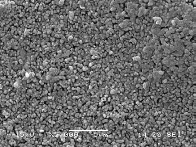
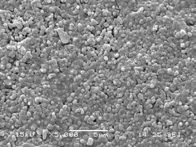
6 The role of PESf phase in the controlled sintering process was investigated by TGA analysis, as shown in Figure 2. PESf can be fully burnt off below 800 C (in air), which is the same as most polymeric materials. The increasing weight loss with elevation of the temperatures indicates a reduction in polymeric phase. While in N 2, a stable weight loss of approximately 60% is obtained from around 800 C, which agrees with the value by directly firing PESf in N 2 at 1450 C for 4 hours. This means that, when such carbon is formed, it can be quite stable in an oxygen free atmosphere. The presence of such a uniform carbon phase would help to stabilize porous membrane structure originally designed at high sintering temperatures, which is impossible to achieve in normal sintering even if certain pore formers such as starch, etc are employed. The carbon formed can subsequently be removed in air, resulting in a highly porous ceramic membrane. It can also be seen in Figure 2 that, observable weight change of PESf in air starts from approximately 400 C, and as a result, the thermal treatment temperature between 400 and 600 C was used for the 1 st step of controlled sintering. 3.2 Effects of controlled sintering on membrane microstructure For the purpose of comparison, precursor fibres of the same structure were sintered using the normal sintering process (Table 2), with the micro-structures shown in Figure 3. Besides a typical asymmetric structure consisting of a sponge-like layer supported onto a finger-like layer (Figure 3 (a)), the inner surface is more porous than the outer surface (Figure 3 (b) and (c)), agreeing well with our previous studies [2, 8]. As for the controlled sintering, after the thermal treatment (1 st step of controlled sintering), there is a significant change in the colour of precursor fibres, as shown in Figure 4. With the increasing temperatures, the samples turn from light yellow to dark brown, together with less and less organic phase left (Figure 2). Such changes agree with the variation in micro-structures of precursor fibres shown in Figure 5. The inner surface of initial precursor fibre is significantly different from the one treated at 400 C and 500 C, the two selected samples, although it is less obvious to the outer surface due to the less amount of polymer. However, after controlled sintering (2 nd and 3 rd steps), the outer surface of controlled sintered samples is more 6
7 porous (Figure 6) with less sintered alumina grains when compared with normal sintering (Figure 3 (c)), proving the role of PESf discussed above in forming a more porous ceramic membrane by suppressing grain growth. It should also be noted that, although adding pore formers is another way of increasing porosity of ceramic membranes, by creating micro-caves inside the membrane, it cannot efficiently affect membrane pore size if the normal sintering procedure is applied. 3.3 Effects of controlled sintering on membrane pore-structure Since the pore structure of such asymmetric hollow fibre membranes is quite unique from conventional ceramic membranes, mercury intrusion was used to investigate the effects of controlled sintering on membrane pore structures, such as pore size distribution and porosity. As can be seen in Figure 7, normal sintered samples show a typical asymmetric pore structure, i.e. bigger pores on the inner surface and smaller pores in the outer sponge-like separation layer, agreeing well with Figure 3. For the controlled sintering with the thermal treatment temperatures between 400 C and 500 C, pore size of the inner surface tends to be reduced slightly, while the one in the sponge-like separation layer is nearly doubled. Although the reason for the minor change in inner surface pore size is yet clear, which may be linked to the more concentrated PESf in precursor fibres (Figure 5 (a-i)), the significant increase in separation layer pore size is in agreement with SEM images of Figures 3 and 6. As has been discussed above, the 1 st step thermal treatment contributes to lower the organic phase in precursor fibres (Figure 2), and the residual organic phase inside the outer spongelike layer is uniformly distributed around alumina particles, as well as in the packed voids among these particles. During the high temperature sintering in N 2 (2 nd step), the residual organic phase turns into carbon and thus helps to reduce the grain growth to prevent the densification of the ceramic membranes with increasing sintering temperatures. After removing carbon (3 rd step), a more porous membrane can thus be obtained. However, if the thermal treatment temperature is too high ( C), an insufficient amount of organic phase remained, thus lack of carbon exists to prevent the membrane densification, and as such, pore size of the outer sponge-like separation layer is comparable with normal sintering. However, the 7
8 trend of reducing inner surface pore size continues with the increasing thermal treatment temperatures, which needs further investigations for a clearer explanation. Besides membrane pore size, porosity is another factor affecting water permeation of a membrane. For asymmetric hollow fibres prepared by the phase inversion assisted process, there is a contribution to the overall porosity from both the fingerlike macro-voids and the sponge-like structure. Since the sponge-like structure plays the major role in water permeation, due to its smaller pore size (Figure 7), its porosity in controlled sintering process was investigated and shown Figure 8. As can be seen, the porosity of the sponge-like structure decreases considerably as the pretreatment temperature was increased from 400/450 to 500 C. This again proves that the residual carbon helps to reduce the grain growth and the densification of the hollow fibre membranes. When the pre-treatment temperature was further increased to 550/600 C, the porosity of the sponge-like structure (~5%) seems to be comparable to the one sintered in a conventional way, which indicates an insufficient amount of residual carbon for a less membrane densification. 3.4 Effects of controlled sintering on water permeation Water permeation of ceramic membranes can be affected by several parameters, such as membrane pore size, porosity and thickness etc.. For the purpose of comparison, water permeation of hollow fibre membranes (sintered in both a normal and controlled way) was tested and shown in Figure 9. As can be seen, water permeation of controlled sintered membranes is always higher than that of the normal sintered one, from a couple of times to approximately 13 times (at 1.38 bar). Furthermore, water permeation of the membranes thermally treated between 400 and 500 C is substantially higher those treated at 550 and 600 C, this trend agrees well with the change of the membrane pore size shown in Figure 7. For membranes thermally treated between 400 and 500 C, densification of membrane is efficiently suppressed due to the presence of carbon. As a result, a higher porosity can be maintained at the high sintering temperature (1450 C), which substantially improves water permeation. Water permeation of the membranes pretreated at 500 C exceeds those of 400 and 450 C, although its porosity is lower. 8
9 This can be linked to the fact that, besides porosity, other factors such pore size distribution and membrane effective thickness co-affect water permeation. For those membranes thermally treated between 550 and 600 C, although the pore size distribution seems to be quite close to the normally sintered sample, the presence of carbon still contributes to slightly higher membrane porosity, for instance the slightly higher peaks at approximately 0.18 µm (Figure 7), leading to a higher water permeation flux than the normally sintered counterpart. 3.5 Effects of controlled sintering on mechanical strength For normal sintered ceramic membranes, the grain growth at high sintering temperatures usually leads to lower membrane porosity (densification) and consequently less water permeation. Meanwhile, proper mechanical strength can be obtained due to the formation of grain boundaries. As has been introduced above, PESf is a continuous phase in both spinning suspension and precursor membranes. This means that it occupies not only the voids formed by the packed ceramic particles, but also any gaps between these ceramic particles. PESf in packed voids acts as a pore structure stabilizer in controlled sintering after being converted into carbon. While the one between ceramic particles, which should be less in quantity (Figure 5), needs to be carefully controlled as it prevents the bounding between ceramic particles. Figure 10 presents the evaluation of mechanical property of normally sintered (NS) and controlled sintered membranes. Both fracture load and strength of controlled sintered membranes increase with the increasing pre-treatment temperatures. Samples thermally treated at 400 and 450 C are considerably weaker than the others, which indicates an excessive amount of polymeric phase between ceramic particles, agreeing with the results shown in Figure 2 that only a small weight loss of PESf occurs in this temperature range. At 500 C, fracture load of controlled sintered membrane is comparable with normally sintered counterparts, while its strength is slightly lower due to the slightly different membrane dimensions. Although its grain boundary may be weaker than the normally sintered sample, because of a small amount of polymeric phase existed between particles, more boundaries due to the smaller grain size (Figures 3 and 6) still contribute to a proper mechanical strength. It 9
10 should be noted that, an increased sintering temperature (1450 C in this study) may potentially help to further improve its mechanical strength without sacrificing membrane porosity and water permeation. The pre-treatment temperatures of 550 and 600 C lead to membranes even stronger than normally sintered one, in which smaller grain size with more grain boundaries may play an important role, the improvement in water permeation is dramatically reduced (Figure 9), indicating a over removal of PESf. Although it is yet thoroughly clear that how the PESf phase changes during the 1 st step thermal treatment, which affects pore structure, grain size, mechanical property and water permeation of resultant membranes, the idea of using PESf phase as a pore structure stabilizer has been proved in this study. Significantly improved water permeation can thus be achieved by reducing membrane densification at high temperatures, without losing membrane strength. Moreover, the idea of this type can be used to fabricate more porous membranes made of other ceramic and inorganic materials. 4. Conclusions In this study, the idea of using PESf as a pore structure stabilizer (in controlled sintering) to alleviate densification of ceramic membranes during high temperature sintering has been investigated. Proper control the quantity of the polymeric phase significantly affects pore structure of the alumina membranes, leading to a more porous membrane with substantially improved water permeation flux. Since the mechanical property of obtained membranes is closely related to the controlled sintering parameter, higher sintering temperatures may be applied for further enhanced mechanical property of ceramic membranes with well maintained pore structure and porosity, which is still a challenge in normal sintering processes. The proposed technique may apply to other ceramic materials in production of highly porous ceramic membranes. Acknowledgement The authors gratefully acknowledge the research funding provided by EPSRC in the United Kingdom (Grant no. EP/G012679/1) 10
11 References 1. Garcia-Garcia FR, Rahman MA, Kingsbury BFK, Li K. Asymmetric ceramic hollow fibres: New micro-supports for gas-phase catalytic reactions. Applied Catalysis a- General 2011; 393 (1-2): Kingsbury BFK, Wu ZT, Li K. A morphological study of ceramic hollow fibre membranes: A perspective on multifunctional catalytic membrane reactors. Catalysis Today 2010; 156 (3-4): Luiten-Olieman MWJ, Winnubst L, Nijmeijer A, Wessling M, Benes NE. Porous stainless steel hollow fiber membranes via dry-wet spinning. Journal of Membrane Science 2011; 370 (1-2): Othman MHD, Droushiotis N, Wu ZT, Kelsall G, Li K. Dual-layer hollow fibres with different anode structures for micro-tubular solid oxide fuel cells. Journal of Power Sources 2012; Wu ZT, Wang B, Li K. A novel dual-layer ceramic hollow fibre membrane reactor for methane conversion. Journal of Membrane Science 2010; 352 (1-2): Zhang JW, Fang H, Hao LY, Xu X, Chen CS. Preparation of silicon nitride hollow fibre membrane for desalination. Materials Letters 2012; Rahaman MN (2003),Ceramic processing and sintering, Marcel Dekker Inc. 8. Kingsbury BFK, Li K. A morphological study of ceramic hollow fibre membranes. Journal of Membrane Science 2009; 328 (1-2): De With G. Note on the use of the diametral compression test for the strength measurement of ceramics. Journal of Materials Science Letters 1984;
12 Table 1 Parameters associated with the stages of sintering for polycrystalline solids [7] Stage Initial Intermediate Final Typical microstructural feature Rapid inter-particle neck growth Equilibrium pore shape with continuous porosity Equilibrium pore shape with isolated porosity Relative density range Idealized model Two monosize spheres in contact Tetrakaidecahedron with cylindrical pores of the same radius along the edges Tetrakaidecahedron with spherical monosize pores at the corners 12
13 Table 2 Sintering parameters for normal sintering and controlled sintering Temperature ( C) Rate Dwelling time From To ( C /min) (min) Atmosphere RT Static air RT 3 - RT Static air RT 5 - (1 st step) RT RT 3 - N 2 (2 nd step) RT RT 3 - Static air (3 rd step) Sintering type Normal sintering Controlled sintering 13
14 Figure 1 Figure 2 Figure 3 Figure 4 Figure 5 Figure 6 Figure 7 Figure 8 Figure 9 List of Figures Schematic diagram of experimental set-up for controlled sintering TGA analysis of PESf and carbon SEM images of asymmetric alumina hollow fibre using normal sintering (a) whole view (b) inner surface and (c) outer surface Photographic image of precursor fibres thermally treated at different temperatures (1 st step of controlled sintering) Selected SEM images of (i) inner surface and (o) outer surface of precursor fibres thermally treated at different temperatures (a) initial precursor fibre (b) 400 C and (c) 500 C SEM images of (i) inner surface and (o) outer surface of controlled sintered membranes with pre-treatment temperatures of (a) 400 C (b) 500 C (c) 550 C and (d) 600 C Pore size distribution of normally sintered membranes and controlled sintered membranes with various pre-treatment temperatures Porosity of sponge-like structure of normally sintered membrane and controlled sintered membranes with various pre-treatment temperatures Pressure dependence of water permeation flux of normally sintered membrane and controlled sintered membranes with various pretreatment temperatures Figure 10 Mechanical evaluation of normally sintered (NS) membrane and controlled sintered membranes with various pre-treatment temperatures (a) fracture load and (b) strength 14

15 Figure 1 15
16 100 Weight change (%) o C PESf in air (5 o C/min) PESf in N 2 (5 o C/min) Carbon from PESf in air (5 o C/min) Temperature ( o C) Figure 2 16
")


17 (a) (b) (c) Figure 3 17

18 Figure 4 18
")
")
")


19 (a-i) (a-o) (b-i) (b-o) (c-i) (c-o) Figure 5 19
")
")
")
")


20 (a-i) (a-o) (b-i) (b-o) (c-i) (c-o) (d-i) (d-o) Figure 6 20
21 Log differential intrusion (ml/g) Normal sintering o C o C o C o C o C Pore size (µm) Figure 7 21
22 40 30 Sponge porosity (%) Pre-treatment temperature ( o C) NS Figure 8 22
23 Water permeation flux (L/(m 2 h)) Normal sintering 400 o C 450 o C 500 o C 550 o C 600 o C Pressure (bar) Figure 9 23
24 Fracture load (N) Fracture strength (MPa) NS Pre-treatment temperature ( o C) NS Pre-treatment temperature ( o C) (a) (b) Figure 10 24