Conformal Coating for Class 3 Hardware: Trending Towards Thinner & Lessons Learned
|
|
|
- Bertram Paul
- 5 years ago
- Views:
Transcription
1 Conformal Coating for Class 3 Hardware: Trending Towards Thinner & Lessons Learned Amanda Rickman Technology Area Director Mechanical, Materials, Structures, and Manufacturing Raytheon Space and Airborne Systems October 27, 2016 This document does not contain technology or Technical Data controlled under either the U.S. International Traffic in Arms Regulations or the U.S. Export Administration Regulations Copyright 2016 Raytheon Company. All rights reserved.
2 Agenda Lessons Learned Challenges within Raytheon Challenges external to Raytheon IPC-CC-830 Changes Ultra Thin Coatings within Raytheon What is driving thin coatings? Examples RF impact considerations


 Ultra Thin Coatings Atomic Layer")
3 Conformal Coating at Raytheon Coatings at the Raytheon SAS/APC Dallas Site: Code Coating Application Methods AR Acrylic Manual UR Polyurethane Dip Coating SR Silicone Spray Coating, Manual XY Parylene Chemical Vapor Deposition (UT) Ultra Thin Coatings Atomic Layer Deposition, Chemical Vapor Deposition
4 Raytheon IPC-CC-830 Conformal Coating Coating Types Raytheon CC Locations UR Texas SR California XY Mississippi AR Massachusetts Application Methods CVD (XY) Spray Coating (SR, UR, AR) Dip Coating (UR) Manual (SR, UR, AR) Arizona Indiana United Kingdom Many more 4


5 Lessons Learned Conformal coating is painful--automate as much as you can Program with 17 CCA board variants Manual application of a 2-part urethane Material issues: short pot life, stuck with legacy material Process issues: manual application Process not optimized: high rework cycles


6 Lessons Learned Proper equipment maintenance is key Vacuum grease in Parylene systems is always the wrong answer Leaving the system in a non-ideal state


7 Lessons Learned Don t make it more complicated than it has to be Adding fluorescing agent to Parylene Gives a feel good test, but trained operators can see Parylene without fluorescing agents. Can give misleading results Absence of tracer does not mean coating not deposited Presence of tracer does not ensure uniform coverage of coating


8 Lessons Learned Check your equipment old equipment goes bad Burnout Furnace PM schedule, inspection Incomplete thermal decomposition of chlorinated hydrocarbons can release carcinogenic compounds


9 Lessons Learned Design for Conformal Coating Connector types commercial, not sealed Blades are PWB-like with regards to masking
10 Reasons to Go Thinner Cost Ease of masking Faster process time RF considerations Taken from Raytheon CC guidance
11 Coating comparison Taken from Raytheon CC guidance PROPERTY URETHANE EPOXY PARYLENE ACRYLIC SILICONE Edge & Point Coverage (Uniformity) C-B C A C C Low Stress Pinhole Free B-C C A C C Dielectric Properties C C A B A Physical Strength C-B B A C B Flexibility B-A C-A B B A Wear/Abrasion Resistance C-B-A B-A B-A C D-C Thermal Coefficient of Expansion C A A B D Water Absorption B A A B C Fluid Resistance B B-A A D D Flammability (Flame Resistance) C C A C B Barrier to Moisture/Gases/Liquids B B A B A Adhesion to Substrates B A C B B Repairability B-C D-C D A B No Contaminating Ingredients B B A B D Particle Immobilization D D A D D UV Resistance B C-D D A A Corrosion Protection B B A D A Condensing Moisture Protection C-A C A C B = key attribute of UT coatings for Raytheon

12 Example: cost, masking Chip and Wire Application Dam & Fill failures Coating only option Traditional conformal coatings not a good fit Masking is cumbersome Too costly to meet commercial pricing Wire bonds under cover Mechanical shield


13 Example: cost, masking, faster process, RF Coating to control material debris from RF & EMI absorbers RF absorber on lid, conductive particulate contamination Unique material, lead time issues Cleaned & Coated
14 Example: RF Performance UT Coatings Required for Minimal Degradation to RF Performance and reduced WVTR Assembly level coatings System level coatings RF impact proportional to the minimum dimension, dielectric constant and loss of materials in high frequency path Minimum thickness of IPC-CC-830 coatings are typically an order of magnitude greater than minimum gaps Pushes UT coatings to <1um Coating Min Max XY ER UR AR SR IPC-CC-830 Thickness (microns)


15 Progress towards IPC-CC-830 RevC Revise MIR & DWV test methods Round 2 Testing 5-33a 5-33awg 5-33aUT Board redesign & fab Final edits to Rev C draft IPC-CC-830 Rev C (with UT) Recommended UT additions to next Rev of Handbook
16 Coating Reliability Approach Raytheon s approach to Qualification of UT Coatings when no applicable industry specification exists Test Structures Test Matrix Failure Distribution Program Specific Environmental Requirements Calculate anticipated life


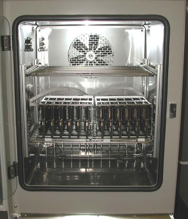
17 Testing details Assemble test structures Accelerated test chamber
18 Coatings vs Traditional Packaging Traditional Ultra Thin PEMs Hermetic Coatings Low ɛ eff good poor good Low Loss good poor good Cost poor good good Weight poor fair good Pkg Density poor fair good Reliability good variable good* Advantages Low effective dielectric constant and loss tangent Low cost coating all devices as a conformal coat High Packing density and low total weight Good compatibility with semiconductor components and typical printed circuit board and surface mount devices Disadvantages *Reliability to be developed for each process type Lower deposition temperature may result in higher impurities in deposited film
19 Acknowledgements Raytheon Engineering Mike Moore James Smith Rachel Ederle Shirley Smith Raytheon Operations Jason Howlett
20 QUESTIONS?