Fundamentals of Corrosion and Their Application to Coil-Coated Metal
|
|
|
- Reynard Sanders
- 5 years ago
- Views:
Transcription

1 Fundamentals of Corrosion and Their Application to Coil-Coated Metal INTRODUCTION This document provides an introduction to the fundamentals of corrosion and its relevance to coil-coated metal. The intent is to provide general background information on the subject that may be useful to both technical and non-technical personnel who are not familiar with this technology. It is not intended to be an exhaustive dissertation on the subject. The topics covered in the paper are -The Corrosion Battle -Electrochemical Aspects of Corrosion -Cell Potentials and the Electromotive Force Series -Forms of Corrosion Relevant to Coil-Coated Metal Galvanic Crevice Filiform -Corrosion Mechanisms of Coil-Coated Metal THE CORROSION BATTLE We fight the battle of corrosion every moment of our lives because of the curse of all undergraduate engineers and scientists thermodynamics!!!!! The Third Law of Thermodynamics tells us (in simplified terms) that the naturally occurring state of matter is its lowest energy state (similar to us on weekends). Metals ordinarily exist naturally as oxides (e.g., iron oxide, aluminum oxide, etc.) because oxides represent their lowest energy state. However, we mine these oxides from the ground, and do various unnatural acts to them such as refining, casting, rolling, and shaping them into a myriad of different shapes. These metals are now in an activated state, and do not want to stay there. They want to revert back to their naturally occurring state oxides, or rust in the case of steel (Figure 1). So that s what we as coil coaters do on a regular basis fight the Battle of Corrosion to maintain the metal in its processed state, and prevent regression to its natural oxide (corroded) state. One of the ways we accomplish this is by applying coatings. ELECTROCHEMICAL ASPECTS OF CORROSION Corrosion can generally be classified as wet or dry. Wet corrosion, as the name implies, occurs when a liquid is present. This is the type of corrosion that is almost always associated with the corrosion of coil-coated metal. This paper will discuss wet corrosion only. Page 1 of 13, 12/2005, Reaffirmed 7/18
2 Dry corrosion occurs in the absence of a liquid phase. Vapors and gases are usually the corrodents. Dry corrosion is most often associated with high temperatures (e.g., attack of metal by furnace gases). Dry corrosion will not be covered in this paper. Wet corrosion is an electrochemical process. The electrochemical nature of corrosion can be illustrated by the attack on zinc by hydrochloric acid. When zinc is placed in dilute hydrochloric acid, a vigorous reaction occurs; hydrogen gas is evolved and the zinc dissolves, forming a solution of zinc chloride. The reaction is: Zn + 2HCl ZnCl 2 + H 2 (1) The chloride ion is not involved in the reaction; therefore, this equation can be written in the simplified form: Zn + 2H + Zn H (2) 2 Thus, zinc reacts with the hydrogen ions of the acid solution to form zinc ions and hydrogen gas. Examining the above equation, it can be seen that during the reaction, zinc is oxidized to zinc ions, and hydrogen ions are reduced to hydrogen. Equation 2 can be conveniently divided into two reactions, the oxidation of zinc and the reduction of hydrogen ions: Oxidation (anodic reaction) Zn Zn e (3) Reduction (cathodic reaction) 2H + + 2e H 2 (4) An oxidation (or anodic) reaction is indicated by a production of electrons. The consumption of electrons signifies a reduction (or cathodic) reaction. Equations (3) and (4) are partial reactions -- both must occur simultaneously and at the same rate on the metal surface. If they do not occur simultaneously and at the same rate, the metal would spontaneously become electrically charged, which is impossible because of the Law of Conservation of Charge. This leads to one of the most important basic principles of corrosion: during metallic corrosion, the rate of oxidation equals the rate of reduction. The above concept is illustrated in Figure 2. Here a zinc atom has been transformed into a zinc ion and two electrons. These electrons are immediately consumed during the reduction of hydrogen ions to form hydrogen gas. Figure 2 shows these two processes spatially separated for clarity. Whether or not they are actually separated, or occur at the same point on the surface, does not affect the above principle of charge conservation. In some corrosion reactions, the oxidation reaction occurs uniformly on the surface, while in other cases it is localized and occurs at specific areas. The corrosion of zinc in hydrochloric acid is an electrochemical process. Any reaction that can be divided into two (or more) partial reactions of oxidation and reduction is termed electrochemical. Dividing corrosion or other electrochemical reactions into partial reactions makes them simpler to understand. Iron and aluminum, like zinc, are also rapidly corroded by hydrochloric acid. The reactions are: Fe + 2HCl FeCl 2 + H 2 (5) 2 Al + 6HCl 2AlCl3 + 3H 2 (6) Although at first sight these appear quite different, comparing the partial reactions of oxidation and reduction indicates that reactions (1), (5), and (6) are quite similar. All involve hydrogen ion reduction, and they differ only in their oxidation, or anodic, reactions: Zn Zn e (3) Page 2 of 13, 12/2005, Reaffirmed 7/18
3 Fe Fe e (7) Al Al e (8) Hence, the issue of hydrochloric acid corrosion is simplified since in every case the cathodic reaction is the evolution of hydrogen gas according to reaction (4). This also applies to corrosion in other acids such as sulfuric, phosphoric, hydrofluoric, and water-soluble organic acids such as formic and acetic. In each case, only the hydrogen ion is active. The other ions such as sulfate, phosphate, and acetate do not participate in the electrochemical reaction. When viewed from the standpoint of partial reactions of oxidation and reduction, all corrosion can be classified into a few generalized reactions. The anodic reaction in every corrosion reaction is the oxidation of a metal to its ion. This can be written in the general form: M M + n = ne (9) In each case, the number of electrons produced equals the valence of the ion. There are several different cathodic reactions that are frequently encountered in metallic corrosion. The most common are Hydrogen evolution 2H + + 2e H 2 Oxygen reduction (acid solutions) (4) O 2 + 4H + + 4e 2H 2O (10) Oxygen reduction (neutral or basic solutions) O H O + 4e 4OH (11) During corrosion, more than one oxidation and one reduction reaction may occur. When an alloy is corroded, its component metals go into solution as their respective ions. More importantly, more than one reduction reaction can occur during corrosion. Consider the corrosion of zinc in aerated hydrochloric acid (Figure 3). Two cathodic reactions are possible: the evolution of hydrogen and the reduction of oxygen. There are two electron-consuming reactions on the surface of the zinc. Since the rates of oxidation and reduction must be equal, increasing the total reduction rate increases the rate of zinc dissolution. Hence, acid solutions containing dissolved oxygen will be more corrosive than oxygen-free acid solutions. Since the anodic and cathodic reactions occurring during corrosion are mutually dependent, it is possible to reduce corrosion by reducing the rate of either reaction. That s where we come in - as coil coaters. If the surface of the metal is coated with paint or other nonconducting film, the rates of both anodic and cathodic reactions will be greatly reduced, and corrosion will be retarded. However, we are not as perfect as we think! Paint films have microscopic (and sometimes macroscopic) defects which allow moisture, salt, acid rain and other corrodents to pass through and contribute to corrosion of the underlying metal. Even if there are no defects in the coating, all paints are semi-permeable membranes in which corrodents can slowly migrate through and reach the surface. This phenomenon will be discussed later. CELL POTENTIALS AND THE ELECTROMOTIVE FORCE SERIES To illustrate the principle of a reversible cell potential, consider the replacement reaction between copper and zinc occurring at equilibrium: Cu Zn + = Cu Zn (12) Page 3 of 13, 12/2005, Reaffirmed 7/18
4 The above reaction is written with an equal sign to indicate an equilibrium reaction. Considering zinc and copper electrodes in equilibrium with their ions, it is apparent that Equation 12 represents their summation. Thus Cu = Cu Zn 2 Cu + Zn e + 2e = Zn = Cu 2+ + Zn (13) (14) To study the above reaction, we can construct an electrochemical cell containing copper and zinc electrodes in equilibrium with their ions, separated by a porous membrane to retard mixing, as illustrated in Figure 4. For purposes of simplicity, the concentrations of metal ions are maintained at unit activity; that is, each solution is one molar. It is necessary that both electrodes be at equilibrium. That is, reactions in each compartment are represented by Equations (13) and (14), and the rates of metal dissolution and deposition must be the same. There is no net change in the system. At certain points on the metal surface, copper atoms are oxidized to cupric ions, and at other points cupric ions are reduced to metallic copper (Figure 5). Equilibrium conditions dictate that the rates of both reactions r1 and r2 in Figure 5 be equal. Similar restrictions apply to the zinc electrode. These equilibrium electrodes are called half-cells, and when the concentrations of all reactants are maintained at unit activity, they are termed standard half-cells. If a voltmeter is connected between the copper and zinc electrodes, a potential difference of approximately 1.1 volts is observed. This is the cell potential that is used in determining the free energy of the overall electrochemical reaction. Any electrochemical reaction can be studied as described above. For example, consider the replacement reaction between copper and silver: Cu Ag + = Cu 2Ag (15) To study this reaction, reversible electrodes of copper and silver can be established, and the potential difference between the two electrodes is 0.45 volt. In this cell, copper is negative with respect to silver. Although it is usually possible to establish a reversible electrochemical cell for any given reaction, the fact that there is an infinite number of combinations makes both the experimental measurements and tabulations of such data impossible. To simplify the representations and calculations of cell potentials, the concept of half-cell potentials has been developed. An arbitrary half-cell reaction is used as a reference by defining its potential as zero, and all other half-cell potentials are calculated with respect to this zero reference. Although any half-cell reaction can be chosen for this standard reference point, the hydrogen-hydrogen ion reaction (2H + + 2e = H 2) is universally accepted. Table 1 lists the half-cell potentials for some electrochemical reactions. This Table is frequently called the EMF series. From the data presented in Table 1, it is possible to calculate the cell potential for numerous electrochemical reactions. Note that the absolute potential difference between the copper electrode and zinc electrode is approximately 1.1 volts, and that the copper electrode is positive with respect to the zinc electrode. Likewise, the potential difference between the copper and silver electrode is 0.45 volt, and copper is negative with respect to silver. Thus, this concept greatly simplifies the calculation of cell potentials. However, in actual corrosion situations, galvanic coupling between pure metals in equilibrium with their ions rarely occurs. Most metals used industrially are alloys of two or more metals, and contain impurities. Therefore, the galvanic series in Table 2, which lists some commercial metals in seawater, is more useful. Page 4 of 13, 12/2005, Reaffirmed 7/18
5 The practical value of all this is that in any electrochemical reaction, the most negative (or active) half-cell tends to be oxidized, and the most positive (or noble) half-cell tends to be reduced. FORMS OF CORROSION RELEVANT TO COIL-COATED METAL There are three forms of corrosion that are relevant to coil-coated metal. They are galvanic; crevice; and filiform. Each of these is discussed in the following. GALVANIC CORROSION As discussed above, a potential difference usually exists between two dissimilar metals when they are immersed in a corrosive or conductive solution. If these metals are placed in contact (or otherwise electrically connected), this potential difference produces electron flow between them. Corrosion of the less corrosion-resistant metal is usually increased, and attack of the more corrosion-resistant material is decreased, as compared with the behavior of these metals when they are not in contact. The less resistant metal becomes anodic and the more resistant metal becomes cathodic. Usually the cathode or cathodic metal corrodes very little (or not at all) in this type of couple. Because of the electric currents and dissimilar metals involved, this form of corrosion is called galvanic, or two-metal, corrosion. The driving force for the current and corrosion is the potential difference developed between the two metals. A classic example of galvanic corrosion is exhibited in galvanized steel. Galvanized steel consists of a zinc coating on a steel substrate. The galvanic series (Table 2) shows that zinc is more anodic (or active) than steel. Therefore, when these two metals are connected in the presence of an electrolyte (e.g., moisture), the zinc will corrode preferentially, and thus protect the steel from corrosion (see Figure 6). The zinc will corrode faster (and the steel slower) than if the two metals were exposed to the same environment, but not coupled! Thus, galvanized steel is an example of how galvanic corrosion can be used to our advantage. Conversely, tin-plated steel represents the opposite effect. Table 2 shows us that tin is noble (or cathodic) to steel. Therefore, when these two metals are connected in the presence of an electrolyte (e.g., soup in a tin can), the steel will corrode preferentially to the tin coating (if there is a pin hole or defect in the tin coating). This preferential corrosion of the steel can result in accelerated perforation of the can. This is obviously a case where galvanic corrosion is not favorable. Galvanic corrosion occurs primarily in the atmosphere. The severity depends largely on the type and amount of moisture present. For example, corrosion is greater near a seashore than in a dry rural atmosphere. Condensate near a seashore contains salt, and therefore is more conductive and corrosive. Atmospheric exposure tests in different parts of the country have shown zinc to be anodic to steel in all cases, aluminum varied depending on environmental conditions; and tin and nickel were always cathodic. Galvanic corrosion does not occur when the metals are completely dry since there is no electrolyte to carry the current between the two electrode areas. Distance Effect Accelerated corrosion due to galvanic effects is usually greatest near the junction, with attack decreasing with increasing distance from that point. The distance affected depends on the conductivity of the solution. This is why the corrosion of galvanized steel is greatest at the cut edge (i.e., where the zinc coating and steel substrate both are exposed to the electrolyte). Page 5 of 13, 12/2005, Reaffirmed 7/18
6 Area Effect Another important factor in galvanic corrosion is the area effect, or the ratio of the cathodic to anodic areas. An unfavorable area ratio consists of a large cathode and a small anode. For a given current flow in the cell, the current density is greater for a smaller electrode than for a larger one. The greater the current density at an anodic area, the greater the corrosion rate. Corrosion of the anodic area may be 100 to 1000 times greater than if the anodic and cathodic areas were equal in size. The area effect of galvanic corrosion is a contributing factor to the so-called cut edge corrosion of coil-coated metal (see Figure 7). When galvanized steel is painted, an unfavorable anode-cathode area ratio exists at the cut edge (i.e., small anode from the zinc surface; large cathode from the steel substrate). This unfavorable ratio can contribute to accelerated corrosion of the zinc, causing blistering and delamination of the paint film. CREVICE CORROSION Intensive localized corrosion frequently occurs within crevices and other shielded areas on metal surfaces exposed to corrosives. This type of attack is usually associated with small volumes of stagnant solution caused by holes, gasket surfaces, lap joints, surface deposits, and crevices under bolt heads. As a result, this form of corrosion is called crevice corrosion. Examples of deposits that may produce corrosion are sand, dirt, corrosion products, and other solids. The deposit acts as a shield and creates a stagnant condition. To function as a corrosion site, a crevice must be wide enough to permit liquid entry, but sufficiently narrow to maintain a stagnant zone. For this reason, crevice corrosion usually occurs at openings a few thousandths of an inch or less in width. It rarely occurs within wide (e.g., 1/8 inch) grooves or slots. Fibrous gaskets, which have a wick action, form a completely stagnant solution in contact with a flange face; this condition forms an almost ideal crevice corrosion site. Crevice corrosion conditions can commonly occur with coil-coated metal. Examples include at fasteners, particularly if they are over-driven to indent and create a liquid reservoir. A clear manifestation of this is the paint blistering seen around fasteners on pre-engineered metal buildings. at lap joints under surface deposits (e.g., dirt, accumulation of grass clippings, etc.) FILIFORM CORROSION Filiform corrosion (filamentary corrosion occurring on metal surfaces) is a special type of crevice corrosion. In most instances, it occurs under paint films. However, filiform corrosion has also been observed on steel, magnesium, and aluminum surfaces covered by tin, silver or gold. Filiform corrosion is an unusual type of attack, since it does not weaken or destroy metallic components, but only affects surface appearance. The attack appears as a network of corrosion product trails. The filaments consist of an active head and a corrosion product tail, as illustrated in Figure 8. The filaments are 1/10 inch or less wide, and corrosion occurs only in the filament head. Interaction between corrosion filaments is most interesting. Corrosion filaments are initiated at edges and tend to move in straight lines. Filaments do not cross inactive tails of other filaments. The most important environmental variable in filiform corrosion is the relative humidity of the atmosphere. Filiform corrosion occurs primarily between 65% and 90% relative humidity. If relative humidity is lower than 65%, the metal is unaffected; at more than 90% humidity, corrosion primarily appears as blistering. Studies have shown that the type of protective coating on a metal surface is relatively unimportant, since filiform corrosion has been Page 6 of 13, 12/2005, Reaffirmed 7/18
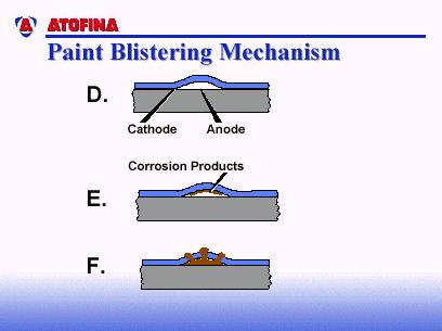
7 observed under paint and metallic coatings. However, coatings with lower water permeability suppress filiform corrosion. Microscopic studies have shown that there is little or no correlation between corrosion filaments and metallurgical structure. Filaments tend to follow grinding marks and polishing direction (i.e., high energy surface sites which are anodic and prone to be active corrosion sites). The most common instance of filiform corrosion of coil-coated metal is prepainted aluminum or steel used or stored in humid environments (e.g., washing machines; building components such as eaves or gutters/downspouts). There is no completely satisfactory way to prevent filiform corrosion. Two approaches to minimize it are to store and use painted metal in low humidity environments, and to use paint coatings of very low moisture permeability. CORROSION MECHANISMS OF COIL-COATED METAL The following will discuss three of the most common corrosion mechanisms of coil-coated metal: a) blistering; b) cathodic delamination; and c) anodic delamination. Paint Blistering Paint blistering due to corrosion starts with a defect - usually on the metal surface (see Figure 9A). The defect can be due to one or more of several sources: a) residual impurities on the metal surface - such as residual hard water salts from process water, residual soils from inadequate cleaning of the metal surface, unreacted pretreatment chemicals, etc.; b) residual solvent from the paint itself; c) impurities on the metal substrate itself - such as oxides, inclusions, etc.; and d) high energy sites on the metal surface such as scratches, polishing/grinding marks, mill roll marks, etc. All these defects are possible sites for paint blistering because all paint coatings are semi-permeable membranes. Thus, there is a driving force for water (assuming there is moisture in the atmosphere) to equalize pressure at both sides of the paint film (i.e., the air-paint interface, and the paint-substrate interface). Water is going to be drawn to the paint-substrate interfacial defects by osmosis (Figure 9B). Eventually, the moisture build-up is so great, the force breaks the interfacial bonds and lifts the paint from the substrate, resulting in blistering (Figure 9C). The literature has reported that the pressure that forms at the interface of these so-called osmotic blisters could be anywhere from psi. Typically, but not always, the center of the defect becomes the anode of a corrosion cell. The area at the advancing interface of the blister becomes the cathode (Figure 9D). Formation of corrosion products occurs (Figure 9E), and eventually the corrosion products become voluminous enough to break through the paint film and give an unsightly appearance (Figure 9F). Cathodic Delamination Another common paint failure mechanism is cathodic delamination. As the name would imply, it s driven by the cathodic reactions of an electrochemical corrosion cell. This might start with a coating defect in the paint film, or perhaps a micro-crack in the paint film after a fabrication step (Figure 10A). Typically, that defect area becomes the anode of an electrochemical corrosion cell. Figure 10B gives examples of the types of reactions that can occur at the anode (i.e., dissolution of the metal into its ions, and the liberation of electrons). The electrons would transmit through the metal to the advancing interface, and take part in a cathodic reduction reaction. The particular cathodic reaction shown in Figure 10B is the reduction of oxygen in a neutral or basic solution. It raises the ph to about This high a ph will solubilize the interfacial bonds and cause additional paint lifting. Eventually, corrosion products will start to protrude through the paint surface (Figure 10E). Cathodic delamination is very common in cold-rolled steel, and also in zinc-coated surfaces such as galvanized, electro-galvanized, and Galvalume steel. Page 7 of 13, 12/2005, Reaffirmed 7/18
.")

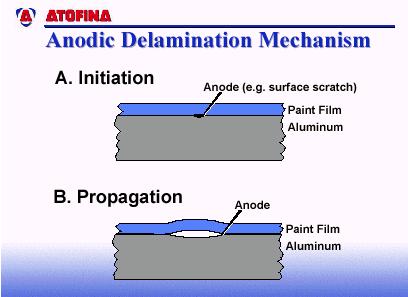
8 Anodic Delamination Conversely, a very common failure mechanism on coil-coated aluminum is anodic delamination. Again, it all starts with a defect - a microscopic defect which becomes the anode of an electrochemical corrosion cell (Figure 11). The propagation of paint lifting with aluminum is typically caused by anodic delamination (i.e., the advancing interface is the anode). The oxide layer on a material such as aluminum is consumed by the anodic reaction, destroying the adhesion between the paint and substrate. It is obvious in all these failure mechanisms that the permeability through the paint film, and interfacial bonding are two of the most important characteristics to controlling the corrosion of painted metal. FIGURE 1: Metals want to stay in their lowest energy state as oxides. FIGURE 2: Electrochemical reactions occurring during corrosion of zinc in air-free hydrochloric acid. Page 8 of 13, 12/2005, Reaffirmed 7/18


9 FIGURE 3: Electrochemical reactions occurring during corrosion of zinc in aerated hydrochloric acid. FIGURE 4: Standard Half Cells Page 9 of 13, 12/2005, Reaffirmed 7/18


10 FIGURE 6: Galvanic Corrosion FIGURE 7: Area Effect of Galvanic Corrosion Page 10 of 13, 12/2005, Reaffirmed 7/18


11 FIGURE 8 FIGURE 9 Page 11 of 13, 12/2005, Reaffirmed 7/18


12 FIGURE 10 FIGURE 11 Page 12 of 13, 12/2005, Reaffirmed 7/18


13 TABLE 1 TABLE 2 Page 13 of 13, 12/2005, Reaffirmed 7/18