Mines and Metals Engineering GmbH
|
|
|
- Blanche Baldwin
- 5 years ago
- Views:
Transcription

1 Mines and Metals Engineering GmbH


2 MME GmbH is officially established and registered company in Düsseldorf, Germany since 1996 to provide engineering services for mining and metals industries worldwide MME GmbH can provide consultancy and support, development in projects from feasibility study guiding customers from concept to commissioning to realize their targets with high quality


3 MME fields: Iron Mines Industries Iron Making Industries Direct Reduction Steel Making Industries Pelletizing plant Rolling Mills


4 MME has a wide range of activities: feasibility studies engineering development and services management for EPC project execution start up and commissioning of plants maintenance and spare parts management systems and automation implementation training and technical assistance services
5 Is the Direct Reduction Technology invented and patented by Mines and Metals Engineering GmbH


6 The PERED Direct Reduction Process converts iron oxides, in the form of pellets or lump ore, to highly reduced product suitable for steel making.. HOT DRI Iron Oxide Pellets Cold DRI HBI

7 The technology improves direct reduced iron process for making DRI To economize energy resources To create a flexible technology for producing direct reduced iron
8 LOWER CAPITAL COST WATER CONSUMPTION MAINTENANCE COSTS ENERGY CONSUMPTION
9 TO USE LUMP ORE UP TO 50% FLEXIBILITY END PRODUCT HDRI / CDRI / HBI TO USE HIGH SULPHUR ORE TO USE LOCAL MATERIAL

10 The MME process has been invented and developed by the experts having rich experience in every field of Direct Reduction process, which has ensured that all the flows of other processes are taken care in this process and provides the optimum and efficient results
11 The reduction of iron oxide in direct reduction process is accomplished by the following reducing agents carbon monoxide (CO) hydrogen (H₂) Fe (Oxide) + CO and/or H₂ ==> Fe (Metal) + CO₂ and H₂O
12 PERED technology for DRI production Is an improved energy efficient technology Is created flexibility to work with different raw material and different energy sources Is reducing the overall cost
13 Where We Innovated Scrubbers Compressors
14


15 Reformer & Heat Recovering Area Centrifugal Compressor Cooling & Seal Gas Compressors


16 Cooling Gas After Cooler Double Port Entry Gas Rotating Burder Feeder Inclined Feed Legs
17

18 DRI PROCESS BLOCK DIAGRAM NG NG STATION MATERIAL HANDLING OXIDE CORE PLANT RO PLANT COMPRESSOR HOUSE W T P PRODUCT HANDLING BRIQUETTING PLANT LABORATORY WORKSHOP CONTROL ROOM MSP


19 FEEDSTOCK OPTIONS ENERGY OPTIONS REFORMER OPTIONS PERED Reformer Steam Reformer 100% Oxide Pellets Up to 70% Lump Ore Up to 10% Solid Fines Natural Gas Coal COAL GAS OPTION Gasifier Syngas Shaft internal diameter 5,65m to 6,65 m MODULE CAPACITY OPTION tpy to tpy COREX Offgas Coke Oven Gas Cold DRI HBI Cold DRI and HBI Hot DRI and Cold DRI Hot DRI and HBI PRODUCT OPTIONS
20

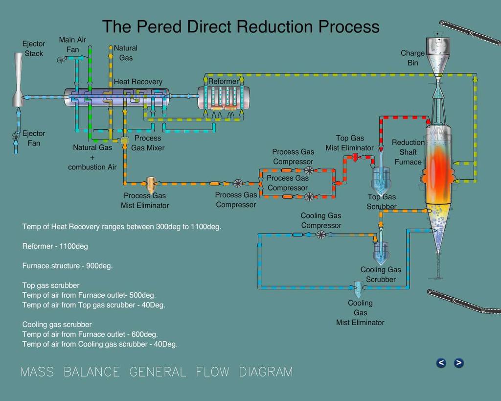
21 Natural Gas is preheated in a REFORMER FLUE GAS RECOVERING EXCHANGER The recovering system get s the heat from gas of the reformer stack The reformer is a multi-bay refrormer with CATALYST tubes

22

23 The system eliminates the particles in Scrubber and gas is compressed and is fed to the furnace bottom product outlet zone

24 The process gas is recycled
25 MME innovation and review on main equipment starts from VERTICAL SHAFT FURNACE PERED Vertical Shaft Furnace is unique of its kind Designed to improve the solid & gas flow patterns to improvise the reaction being taken place Designed to have higher production rate / volume of reduction zone.

26 REDUCTION UPPER ZONE TRANSITION MIDDLE ZONE COOLING LOWER ZONE


27 Shaft Furnace Top ( Reduction ) Zone Oxide feeding & distribution inside the furnace by special feed pipes. Optimizing the ratio of height to diameter which improves utilization of the furnace. Optimizing reduction reaction with: No equipment in the furnace reduction zone Reduces fines generation Improves material distribution inside the furnace Increase effective reduction volume Eliminates possible pollution due to gas leakage Capital cost reduction Maintenance cost reduction

28 Shaft Furnace Top ( Reduction ) Zone Design caracteristics: Dual top gas off take design from the top dished end Better burden temperature profile to achieve uniform product quality Reduce fines/pellet carry over & thus improves the refractory life at top gas duct Optimise furnace size/ réductions zone volume Lower off take température due to improve efficience thus lower load on scrubbers
29 Design caracteristics: Dual reducing gas injection Flexibility to have different gas composition and temperature with oxygen injection Better utilization of the bustle gas Improves distribution of gas in the furnace Improve productivity and quality Uniform bed temperature across the furnace Eliminate clustering possibility Flexibility to use lump ore Rectangular bustle ports design Shaft Furnace Reduction Zone Tapered refractory construction to take care of DRI swelling Bustle Port arrangement Specially designed ports for better gas injection and better maintainability


30 Shaft Furnace Reduction Zone In-situ reforming Hot bustle gas with a certain percentage of CH₄ and CO₂/H₂O, in contact with metallic iron, which acts like catalyst generates additional reducing gas inside the shaft furnace, in fact, the shaft furnace acts like a reformer In-situ reforming reactions are: CH₄ + H₂O CO + 2H₂ DH>0 CH₄ + CO₂ 2CO + 2H₂ DH>0 On one hand, the endothermic In-Situ reforming needs high bustle gas temperature. On the other hand, pellet/lump degradation, fine generation and clustering in the bustle area will occur at higher bed temperature. State of the art PERED double bustle port optimizes the amount of CH₄ in the bustle gas which is required to control the bed temperature.
31 Cooling Gas Off Take Arrangement


32 Shaft Furnace Lower Cooling Zone Design caracteristics: State of the art 360 degree rotating burden feeders Better and uniform performance Feeding burden with 4 independently controlled rotating shafts No water jacketing as it is in the cold zone Dislodging of cluster if formed, by reverse rotation and speed control Cooling gas Offtake and China hat Injection of cooling gas to cone from outside header + Uniform hot cooling gas collection by shaped Offtake No refractory in the header which can cause failure
33 REFORMER


34 Top Gas Scrubber & Cooling Gas Scrubber 3 Dimensional View TOP GAS SCRUBBER COOLING GAS SCRUBBER

35 Compressors Operation with higher pressure by proven system Dry process gas leads to higher gas flow with the same system, which in turn increases the production or for same production reduces power consumption.
36 PERED technology brings the following advantages Lower capital investment Lower energy & operation costs Lower environment pollution Jumbo module for more than 1 MTPY Option for hot DRI / HBI Flexibility to use high sulphur ore
37
38 MAIN PROJECT DATA Plant nominal capacity of 800,000 TPY of oxide pellet 5mm 35mm Main specification data Value Max diameter Approx 5.5m Total Height 52m approx Hourly produciton rate 105t/h Plant operating time 8000 hrs/year Operating temperature of furnace 850 C Normal furnace operatingpressure top 0,6kg/cm² g Normal furnace operatingpressure bottom 2.1kg/cm² g max Reduction gas requirement Nm³/h Reduction gases per ton of product 1600 Nm³ DRI density 1.7 t/m³ Oxide density 2.3 t/m³
39 THE PERED DRI PROJECTS SHADEGAN PERED (0.8 MTPY) TURN KEY MIYANEH PERED (0.8 MTPY) ENGINEERING & EQUIPMENT SUPPLY NEYIRIZ PERED (0.8 MTPY) ENGINEERING & EQUIPMENT SUPPLY BAFT PERED (0.8 MTPY) TURN KEY CSTM PERED (0.3 MTPY) ENGINEERING & EQUIPMENT SUPPLY - WITH SYN GAS FROM COKE OVEN P.R. OF CHINA
40 MEGA MODULE DRI HOT CHARGING OF DRI TO STEEL MAKING HOT DRI TRANSPORT BRIQUETTING OF COLD DRI
41 MME Germany Headquarters MINES & METALS ENGINEERING GmbH Tersteegen-Str. 10 D Düsseldorf GERMANY tel fax Connection in 10 minutes from Düsseldorf International Airport Connection in 1 hour from Düsseldorf Weeze Airport MME Iran Branch Office MINES & METALS ENGINEERING Tehran Fourt Alley South South Piroozan St. Hormozan St. Shahrak Gharb Tehran / IRAN tel fax info@mme-co.ir MME China SIRIUS Co. Ltd. MME TRADING SHANGHAI Co., Ltd. Room West Nanjing Road Jing an District, Shanghai P.R. CHINA tel fax info@sirius.net.cn