LASER ASSISTED SURFACE FUNCTIONALIZATION
|
|
|
- Tracy Robbins
- 5 years ago
- Views:
Transcription


1 VACUUM DEPOSITION TECHNOLOGIES FOR FILMS & COATINGS SEVILLA, 20 FEBRUARY, 2014 LASER ASSISTED SURFACE FUNCTIONALIZATION G. F. de la Fuente

2 Outline: 1.- LASER TECHNOLOGY: FUNDAMENTALS FOR PEDESTRIANS. 2.- LASER-MATERIAL INTERACTION. 3.- EXAMPLES IN MATERIALS SCIENCE & TECHNOLOGY SURFACE HEATING 3.2. MELTING AND DIRECTIONAL SOLIDIFICATION 3.3. ABLATION
3 1.- LASER TECHNOLOGY: FUNDAMENTALS FOR PEDESTRIANS What is a LASER? Light Amplification by the Stimulated Emission of Radiation Pumping Laser beam emission Active medium R 1 =100% R 2 <100% Elements within a Laser Cavity: 1.- Active Medium 2.- Excitation mechanism 3.- Optical resonator
4 LASER SYSTEMS FOR INDUSTRIAL APPLICATIONS LASER TYPE SPECTRAL RANGE ACTIVE MEDIUM EXCIMER nm UV Excimer gas mixture (XeCl, ) DIODE nm n-ir P-N junction (semiconductor) Nd:YAG 1064 nm n-ir YAG single crystal doped with Nd 3+ CO µm mid-ir Gas mixture: CO 2, N 2, He Fibre 1070 ±10 nm n-ir Doped fibre (Yb 3+ ) Disc 1030 nm n-ir Single crystal thin disc of Yb:YAG,


,... kw: materials processing,.")
5 LASER SYSTEMS FOR INDUSTRIAL APPLICATIONS Laser diode system Junction Conduction Band Type P Semiconductor type N Semiconductor Valence Band E g Unpolarised P-N junction e - /hole recombination Holes e - Photons of energy h Polarised P-N junction APLICACIONES: mw: fibre optics communications, medicine, noncontact measurements (metrology),... kw: materials processing,... Power range: 0-2 W (low) 0-6 kw (high)
 2 Pump Bands 1,5 4 F 3/2 1 4 I 15/2")

 Scientific & Measurements (nuclear fusion,")
6 LASER SYSTEMS FOR INDUSTRIAL APPLICATIONS Nd:YAG Laser system Energy (ev) 2 Pump Bands 1,5 4 F 3/2 1 4 I 15/2 Laser transition 1,06 m 0,5 4 I 13/2 4 I 11/2 4 I 9/2 APLICATIONS: Materials processing (cutting, welding, marking,...) Scientific & Measurements (nuclear fusion, environment,...) Applications in medicine Power range: 5 W-5 kw


 Fast transition Fast Transition Fast transition (000)")
 Others Power range: 0.")
7 LASER SYSTEMS FOR INDUSTRIAL APPLICATIONS CO 2 Laser De-excitation from higher energy levels 1. Laser beam 2. Beam modifying unit 3. Exit mirror 4. Cooling water 5. RF excitation 6. Cooling water 7. Back reflecting mirror 8. RF excitation discharge 9. Electrodes Fast transition (002) Fast transition (001) 9,6 m 10,6 m (100) Fast transition Fast Transition Fast transition (000) Fundamental state (020) (010) APLICATIONS: Materials Processing (cutting, welding, thermal treatment,...) Others Power range: kw SLAB 20 W-20 kw Others

8 2.- Laser-Material Interaction LÁSER PARAMETERS Wavelength IRRADIANCE Photon-electron interaction Physico-Chemical mechanisms Laser beam Temperature Profile Sustrate Heat Affected Zone Vapor plume Plasma plume Heating Melting Evaporation Plasma formation
9 LASER LIGHT LAMP 8 W, 20 Hz, 5 ns, =1064 nm, 80 MW pulses, focus 300 µm 2 2.6x10 13 W/cm 2 QTH lamp, 1 kw, cw, range <400 to >2500 nm, focus 3 cm W/cm 2 Collimated beam Noncollimated
10 Characteristic Emission of different light sources 355 nm 810 nm UV IR QTH 266 nm 532 nm 1064 nm

11 2.- LASER-MATER INTERACTION ULTRAVIOLET WHAT WE CAN SEE
12 2.- LASER-MATER INTERACTION VISIBLE
13 2.- LASER-MATER INTERACTION INFRARED WHAT WE CAN SEE

14 HUMAN SUBJECTS AFTER A PROLONGED IR EXPOSURE

15 HUMAN SUBJECTS AFTER A PROLONGED UV EXPOSURE
 Pulse Width femtoseconds(10-15")
16 2.- LASER-MATER INTERACTION Irradiance P(W) E/pulse(J) Continuous Regime Pulsed milliseconds(10-3 s) Pulse Width femtoseconds(10-15 s)


17 Laser Irradiation Surface Heating Ablation Melting + Rapid / Controlled Solidification Local high temperatures Solid State Diffusion or High thermal gradient Sublimation Transitory melting+ evaporation Shockwaves-particle/grain ejection

18 HEATING IS THERE ATOMIC DIFFUSION?


19 CERAMIC MACHINING IN PLASTIC REGIME SiN Ring- no microcracks observed 115 µm ca. 90 x 20 Diode Laser 1.2 kw, l=940 nm 1.5 x 5 mm beam 1000 C

20 LASER CLADDING Material is supplied simultaneously to laser irradiation
21 Stainless Steel cutting Melting + GAS pressure

22 Diode Laser Emission at 808 nm Cylindrical lens Focal: 5 cm line Travelling Stage

23 Laser incidence (Line) Sintered products Reactants Diode Laser source (cw mode)


24 Laser Zone Melting of Al 2 O 3 -ZrO 2 Eutectics V=72 mm/h, Al support 2 R = 0.9x10⁻¹⁷ m 3 /s A. Larrea et al, J. Eur. Ceram. Soc. 22 (2002)

25


26 Support Al 2 O 3 Ag *Metallic support reduces thermal gradients on the sample
27 Externally heated support vs. Ic (Critical Current in A) T (ºC) Ic (A) Observations 25ºC 9.6 cracks 145ºC 13.2 cracks 150ºC 14.0 cracks 330ºC 16.0 no cracks 430ºC 27.5 no cracks (CO 2 ) = 10.6 µm; v=36 mm/h Tsupport Ic M. Mora, C.I. López Gascón, L.C. Estepa, J.A. Gómez, L.A. Angurel,J.C. Diez, G.F. de la Fuente Supercond. Sci. Technol. 17 (2004)
28 Cutting blown glass with a CO 2 Laser ADVANTAGE OF LOCALIZED THERMAL STRESS

29 THERMAL STRESS/SHOCK 30

30 LASER FURNACE

31 CONTINUOUS LASER FURNACE: THE CONCEPT SURFACE AT EXTREME TEMPERATURE SUBSTRATE AT MUCH LOWER TEMPERATURE

32 I. de Francisco, V. Lennikov, L. A. Angurel, L. C. Estepa, R. Lahoz, G. F. de la Fuente ICMA (Materials Science Institute of Aragón) CSIC-University of Zaragoza, Zaragoza. F. Rey-García, C. Bao UA Óptica & Micro-Óptica GRIN, University of Santiago de Compostela.

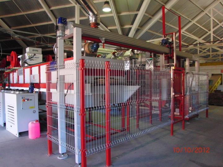

33 15 m long LaserFiring Prototype


 LASER")
34 Novelty: Laser processed glass/torrecid ICALEO 2010, M308 Lahoz et al (ICMA) LASER MICROPROCESSING SESSION 3


35 SURFACE ABLATION Laser Cutting STRUCTURING & Engraving AND IN-SITU of Porcelain PIGMENT Tile DEVELOPMENT
36 THE LASER FURNACE LONG PULSE & CW MODE LASERS + HEAT (Laser Furnace)...MAY ALLOW TO... SURPASS THE INTRINSIC PROCESSING LIMITS OF KNOWN MATERIALS: GLASS > 1500 ºC CERAMICS > 2950 ºC DEVELOP NOVEL INDUSTRIAL MATERIALS TRANSFORMATION & FABRICATION PROCESSES 37

37 ABLATION
38 Laser Ablation Process Laser beam Combination of phenomena: Melting + Evaporation Direct Sublimation Shock Waves Particle & melt drop ejection Energy per pulse (J/cm 2 ) Plasma Melt expulsion Damage Threshold Substrate Ablation Threshold Laser pulses Ablation Process

39 39

40 SURFACE ABLATION STRUCTURING COMBINED WITH PVD 40

41 SURFACE ABLATION STRUCTURING COMBINED WITH PVD 41

42 SURFACE ABLATION STRUCTURING COMBINED WITH PVD 42
43 PLD-CLD

44 3D image inside a thick glass block 532 nm Laser, ns or ps pulses Ablation at the focal spot
")

45 Laser Surface treatment of a fan blade (Laser Pinning) Nd:Glass Laser, 100 J pulses at 6 Hz Effect of a single pulse on Al

46 STENT FABRICATION


47 Mixed Processes MELTING + EVAPORATION in cw mode Ablation in pulsed mode ALSO Photochemical or Photothermal Processes

48 POLYMER BOX MARKING

49 ON-LINE COMPUTER KEYBOARD MARKING POLYMER + PHOTOSENSITIVE ADDITIVE

50 Stainless Steel Perforation


51

52 PAINT DESORPTION OVER ALUMINIUM ALLOY

53 EVEN ON THE RUN
 J.")
 A. R. GONZÁLEZ-ELIPE, J. P. ESPINÓS, V.")
54 SURFACE DESORPTION OF OXIDE LAYER ON STEEL L. C. ESTEPA, V. LENNIKOV, R. LAHOZ, I. DE FRANCISCO, L. A. ANGUREL, C. LÓPEZ-GASCÓN, J. C. DIEZ (ICMA) J. CARDA, J. M. PEDRA (UJI) C. GÓMEZ-REINO, C. BAO, M. T. FLORES, F. REY-GARCÍA (USC) A. R. GONZÁLEZ-ELIPE, J. P. ESPINÓS, V. RICO (ICMSE) THANK YOU!