New materials for AFC anodes
|
|
|
- Joshua Stone
- 5 years ago
- Views:
Transcription
1 New materials for AFC anodes Application of Novel Electrode structures developed for SOFC technologies into AFC systems to increase anode performance and cycling durability.

2 Alkaline fuel cells background Alkaline fuel cells are attractive due to; good reaction kinetics high electrolyte conductivity low operating temperature wide selection of possible electrocatalysts simplicity Challenges exist around; AFC Energy installation at Akzo Nobel in Germany highly caustic environment additional system complexity to remove carbon dioxide or obviate the need to. Some of the normal FC electrode stability issues
3 Recirculating electrolyte AFC Depleted fuel & some H 2 O Hydrogen Anode OH - Cathode O 2 depleted air & some H 2 O Air with low CO 2 KOH reservoir Circulating electrolyte advantages water management thermal management carbonate management
 High values up to 9.0 A cm -2 @ 0.")

4 AFC anodes Pt was the catalyst of choice for the most noted AFC application current densities of >4.0 A cm 0.6 V were easily achieved (4barg pure H 2 / O 2-120⁰C) High values up to 9.0 A cm 0.7 V reported Orbiter units operated at very high cell voltage in practice maximising efficiency For less exotic applications Ni and other lower cost catalyst provide a commercial solution Current densities of A cm 0.7 V using atmospheric pressure H 2 and low CO 2 air achieved with low cost catalyst giving a viable product for large scale stationary applications UTC AFC orbiter unit AFC Energy CORE system
5 AFC anode challenges Electrocatalyst particle coarsening and migration Analogous to other FC types, this may occur at certain points in cycling. Electrode activation Ni is a common low-cost anode catalyst choice however passivating films are difficult to reduce at the low operating temperatures used. Small leakage currents are always likely to exist in recirculating electrolyte stack. If electrodes do not all activate rapidly and at the same time inactive anodes can be polarised to support the leakage preventing their activation and producing a cell voltage inversion.

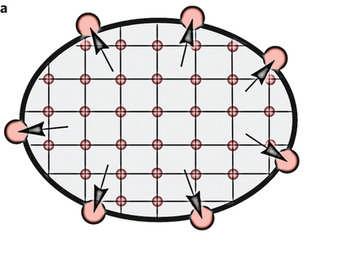
6 Project Overview Material La 0.4 Sr 0.4 TiO 3 based materials with high room temperature electronic conductivities Novel exsolution process forms highly stable nanoparticles embedded in surface Electrodes High and stable active surface area with low resistive losses to current collector backing The perfect AFC anode? shows the surface decorations achieved after sintering at 1350 o C in air and then reducing for 20 hours at 950 o C in 5% H 2 /Ar
 in the")
7 Electronic conductivity of substrate Conductivity vs. Temperature measured on cooling for samples reduced (5%H 2 /Ar) in the testing jig at 880 o C.
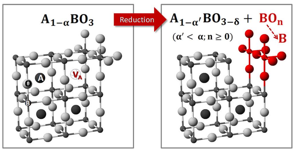
8 Exsolution

 10 μm 1 100")
9 Terrace separation Terrace edge La0.4Sr0.4NixTi1-xO3-x/2 (x = 0.03, 5% H2, 930 C, 20h then wet 5% H2, 900 C, 100h) 10 μm nm
10 Overview of electrode structure The powders developed will be used as drop in substitutes in the current AFC Energy electrode structure and fabrication processes. Typical AFC anode Proposed AFC anode Liquid electrolyte (KOH) Gas Diffusion Layer Carbon black powder High surface area nanopowder electrocatalyst Hydrophobising and binding agent Novel SOFC perovskite system with exsolutions of intimately embedded electrocatalyst
11 Outline of project structure WP1 Materials (St Andrews lead) Process development for greatest number and coverage of active exsolutions of Ni. Powder size and morphology development (strongly influences how electrodes wet). Formation of representative electrode WP2 Electrode performance and durability (Lancaster lead) Establish performance (day tests) under typical AFC conditions. Impedance characteristics. Establish constant load and cycling tolerance (load and startup / shutdown). Observing changes in electrode impedance and physical changes post test.
12 Progress to date Project started at kick-off meeting at AFC Energy 24th June. Initial materials requirements discussed and first activity tests. The role of titanate particle size and morphology will be very important. Dedicated standard AFC testing rig being assembled in DSEAR compliant FC lab in Lancaster for automated 24/7 running. Fabrication equipment transferred to Lancaster labs for small electrode production. Project duration ca. 12 months

13 The Project Team Academic team Dr. Richard Dawson Dr. Anant Patel Industrial Collaborators Prof. John Irvine Dr. Cristian Savaniu Dr. Anushree Khandale Dr. Gene Lewis Dr. Hugh Sutherland

14 Acknowledgements Thank you for your kind attention