The in-service inspection of coated steel welds using Eddy-Current Techniques
|
|
|
- Brice Booker
- 5 years ago
- Views:
Transcription

1 Journal of Physics: Conference Series The in-service inspection of coated steel welds using Eddy-Current Techniques To cite this article: B J Brown et al 2012 J. Phys.: Conf. Ser Recent citations - Sustainable asset integrity management: Strategic imperatives for economic renewable energy generation Chinedu I. Ossai et al View the article online for updates and enhancements. This content was downloaded from IP address on 18/10/2018 at 23:02
2 The in-service inspection of coated steel welds using Eddy- Current Techniques BJ Brown 1, M Zaid 2, PD Picton 2 and SJ Mabbutt 2 1 Training Centre Manager Aberdeen, TWI Ltd 2 School of Science & Technology, The University of Northampton, St George's Avenue, Northampton NN2 6JD, UK bill.brown@twi.co.uk, Muhammad.Zaid@northampton.ac.uk, Phil.Picton@northampton.ac.uk, Steve.Mabbutt@northampton.ac.uk Abstract. Traditionally surface crack detection in coated Ferritic Steel Welds with Eddy- Current Techniques has been difficult due to the change in material properties in the Heat Affected Zone. These typically produce signals larger than crack signals. Sophisticated probe design and construction, combined with modern electronic equipment, have largely overcome the traditional problems and now enable the advantages of Eddy-Current Techniques to be applied to In-Service Inspection of Coated Ferritic Steel Structures in the as-we!ded conditions. Specifically, the advantage of the technique is that under quantifiable conditions an inspection may now be carried out through corrosion protection systems. It is the intention of this paper to review the current information available, establish the limiting parameters of the technique and detail the practical experiments conducted to determine the extent of the limiting parameters. The results of these experiments are detailed. Having determined the limiting factors, outline testing procedures have been established together with relative sensitivity settings. 1. Introduction It is good practice to inspect large structures during their service life looking for the effects of fatigue loading. The resulting fatigue cracks tend to initiate at the high stress points such as welds and attachments or apertures. It is therefore common to inspect the toes of the welds and associated Heat Affected Zones for signs of cracking due to the in-service conditions such as fatigue loading. The common Non-Destructive Testing (NDT) method for the detection of such fatigue cracks in carbon steel structures is Magnetic Particle Inspection (MPI). This method applies magnetic fields to the area under test and detects changes in the magnetic flux due to the surface breaking defects. Unfortunately, to achieve the correct level of detection, it is necessary to remove the coatings from the areas to be examined prior to the application of the MPI method. The removal and subsequent re-instatement of the coating is expensive and time consuming. The removal and re-instatement of protective coatings is not a simple process. In some parts of the world, at the equator for example where it is generally hot and humid, the re-instatement of the coatings can be a big problem. If a reliable NDT method could be found that negated the removal of the protective coatings and maintain the appropriate level of defect detection then this could be implemented as a primary inspection with MPI as the definitive method. The removal of a very small area of the protective coating would be easy, cheap and more importantly, for a purpose. Published under licence by Ltd 1
3 The cost saving on the application of traditional methods would be very significant indeed. The cost savings have been estimated at 80% of that for MPI. The cost savings being achieved through not removing and re-instating the coatings, Eddy-current techniques have the potential to inspect through conductive and non-conductive coatings and detect surface breaking defects. An evaluation programme, based on defect detectability relative to Magnetic particle inspection on representative samples was conducted by the Scottish School of NDT in the late 1980s.[1] An overview of the results was presented at Offshore Europe in The details of the research were never published. As a result, little or no formal information on the practical limitations of the technique is available in the public domain for review and comment. Most of the evaluation work has been practical based. This has involved testing verified samples or offshore structures under managed and controlled conditions, typically testing the structures by eddy-current techniques followed by Magnetic Particle Inspection and comparing the results. These have been conducted in many locations worldwide including United Kingdom, USA, Middle East, Scandinavia and West Africa. Practical testing procedures were developed as a result of these trials. [2]. These procedures were subsequently adopted by BSEN Standards and issued under BS EN 1711:2000, Non-Destructive Examination of Welds Eddy-current examination of welds by complex plane analysis.[3]. Formal training and certification became essential, hence a set of practical training notes were developed. In-Service Inspection of Coated Steel Welds Using Eddy-Current Techniques, Practical Tuition- General Guidelines. [2]. It is the intention of this project to conduct practical experiments on representative samples in order to establish the limiting parameters of the technique. 2. Practical application, material properties and coating assessment 2.1. Representative Samples Six samples representative of the weld configurations, coating condition and constituents to be tested in the Oil & Gas Industry were used for evaluation purposes. These were: 1. Y weld configuration, half coated with acrylic finish, known defects, figure T weld configuration, coated with coal tar epoxy finish, known defects, figure T weld configuration, coated with acrylic finish, known defects, figure Rat-hole weld configuration, coated with acrylic finish, known defects, figure Gusset plate weld configuration, coated with acrylic finish, known defects, figure Node weld configuration, not coated with known defects, figure Evaluating Material Properties & Defect Detection The choice of probes/coils to evaluate the material properties and detect defects in steel components will depend on; a) the ability of the probe to gain access to the areas to be inspected b) resolve the properties to be identified such as coating thickness and constituents c) the ability to resolve the relevant defects under coatings and in steel. 2


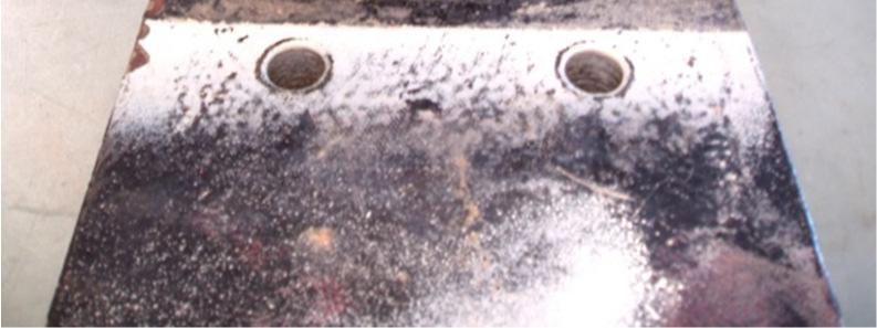
4 25th International Congress on Condition Monitoring and Diagnostic Engineering Figure 1. Y weld configuration, half coated with acrylic finish, known defects. Figure 2. T weld configuration, coated with coal tar epoxy finish, known defects. Figure 3. T weld configuration, coated with acrylic finish, known defects. Figure 4. Rat-hole weld configuration, coated with acrylic finish, known defects. Figure 5. Gusset plate weld configuration, coated with acrylic finish, known defects. Figure 6. Node weld configuration, not coated with known defects. 3
5 Absolute Probe. The absolute probe is ideal for access purposes and will be ideal for evaluating the material properties and the coating thickness by analysing and measuring the lift-off signal. The specification for the absolute probe is: a) Be able to determine the general material properties b) The ability to measure the range of predicted coating thickness. In the Oil & Gas Industry this would be in the range 0.3 to 1.5mm thick, 2.0mm maximum. This is determined by the coating thickness on the structural steel components allowing for the effects of gravity in the bottom weld toes Weld Probe. The weld probe s characteristics are, in effect, to reduce the lift-off signal as much as practicable due to the fact that the lift-off is, in many ways, the noise being generated by the coils. This reduction in the lift-off signal negates the use of the weld probe for determination of material properties and coating thickness The limiting parameter of component material relative to the 50D steel calibration block The limiting parameter is ± 5 0 of the lift-off obtained from the 50D steel calibration block. Out-with this it will be necessary to investigate the reason for the change and evaluate if a more relevant calibration block is necessary or if it is a conductive coating Summary of probe/coil initial evaluation The absolute probe will be used to determine all the pre-test conditions Coating Assessment Measurement of Non-Conductive Coating. Two carbon steel samples were used to illustrate the results of the techniques employed to the measurement of non-conductive coatings, figures 1. and Measurement of conductive coating(s) on carbon steel substrate. Four samples of carbon steel were coated with Thermal Sprayed Aluminium (TSA). The coating thicknesses were physically measured and the eddy-current technique applied Summary of Results Non-Conductive Coating. The thickness of non-conductive coatings was achieved using known thicknesses of plastic shims as a calibration. Thicknesses up to 2.0mm thick could be accommodated Conductive Coating. The thickness of conductive coating was achieved by measuring the phase change from the lift off from the carbon steel calibration block using known thicknesses of Aluminium foil as a reference. There is no direct comparison in coating thickness between the aluminium foil and the TSA coating other than the same phase angle will be equivalent in eddy-current response. 3. Practical applications defect detection 3.1. The criteria for defect detection are as follows 1. Only surface breaking defects will be detected. 2. The minimum size of defect to be detected in the as-welded condition is 1.0mm deep x 5.0mm long. This is the defect detection level applied to visible MPI inspection of welds. 4


6 25th International Congress on Condition Monitoring and Diagnostic Engineering 3. In order to ensure adequate sensitivity the 1.0mm deep slot in the 50D steel calibration block is the reference, figure The eddy-current signal shall be set at 80% full screen height. In effect the bottom reference point is set at 10% and the signal amplitude set 10% below the top of the screen, therefore the signal amplitude is stated as Full Screen Height Relative Sensitivity Setting The Relative Sensitivity Setting shall be the above reference level plus compensation for the maximum coating thickness measured by the absolute probe plus compensation for any Stand-off due to the geometry of the area under test Defect detection - Absolute Probe The detection of the required size of defect through the 2.0mm thick non-conductive coating in the aswelded condition on representative samples was not possible Defect detection Weld probe Figure 7. Eddy-Current responses from the 0.5, 1.0 and 2.0mm deep slots in the 50D steel calibration block. Figure 8. Eddy-Current responses from the toe of the weld on sample shown in Figure 3. Signals show defect free and defective area(s). The defect areas on the weld toe were easily recognised against the defect free area as illustrated in figure Summary of Probe Evaluation Reference was made to the guidelines in BS EN ISO : 2008, Non-destructive testing Equipment for eddy-current examination. Part 2: probe characteristics and verification [4]. The absolute and the weld probe complement each other. The absolute probe, using the lift-off signal is very efficient in determining the properties of the material and is capable of measuring the coating parameters necessary for the work in hand but is very poor when detecting surface breaking defects in 50D steel. The weld probe has little or no lift-off thereby reducing the surface noise from the steel surface and is efficient when detecting surface breaking defects in 50D steel. 5
7 4. Weld probe evaluation 4.1. Manufacturing process - possible manufacturing anomalies that may affect performance During manufacture it is possible for the coils to be knocked out of position. It is necessary to ensure the coils are set properly in place prior to use as well as identify the other parameters that may affect performance. These parameters have been identified as: 1. Coil Symmetry 2. Lift-off evaluation 3. Coil Windings 4.2. Eddy-Current Distribution in Carbon Steel Using standard techniques and the 1.0mm deep slot in the 50D steel calibration block as reference the result is as illustrated in figure 9. It is therefore evident that the eddy-current field is directional. The rationale for the 50% level is to determine when the orientation of a defect relative to the direction of scanning will still detect a defect. When the reference signal is set vertically upwards from the 1.0mm deep slot in the 50D steel calibration block, when the coil is turned 90 0 to this is and traversed over the slot the response will be vertically down i.e. equal and opposite to each other. The probe can be moved positive, negative, left or right Summary of Result The orientation of the defect is critical. It is therefore necessary when a low response is obtained to change the orientation of the probe to maximise the defect response Weld probe evaluation - ability to compensate for increasing non-conductive coating and maintain a relative sensitivity The ability of the eddy-current to be induced into the substrate through the coating will be frequency dependent. The primary considerations, however, in this exercise are defect detection and relative sensitivity. The exercise was carried out at various frequencies and the result was that the lower the frequency the lower the sensitivity. It is therefore critical to keep a relative sensitivity setting using the same reference slot at pre-determined amplitude. The results are illustrated in figure Weld probe evaluation - ability to compensate for increasing conductive coating and maintain a relative sensitivity When employing a conductive coating the eddy-current is preferentially induced into the conductive coating. This variation will also change with the conductive coating material (electrical conductivity). The greater the coating thickness the less eddy-current will be induced into the substrate. Defect detectability and relative sensitivity are therefore very difficult to quantify and the calibration prior to inspection must be specific to the actual testing conditions. It may be necessary to reduce the frequency to penetrate the conductive coating. The defect detection will, of necessity, be reduced due to the change in the induced eddy-current in the substrate. When testing Thermal Spray Aluminium coated carbon steel it is necessary to ensure the eddycurrent is reaching the steel and is capable of detecting cracks on the surface of the steel as it is likely that the initial crack will be in the steel and will not penetrate through the ductile coating. The weld probe will operate within a frequency range of 20kHz to 350kHz. At 20kHz the maximum TSA coating tolerated is 200µm and the defect detection has been reduced to 3.0mm deep x 20.0mm long. 6
8 100% 50% % Little or no response from this area. 50% Little or no response from this area. 50% % Little or no response from this area. Little or no response from this area. 5.0mm 5.0mm 100% 50% 50% Figure 9. Weld probe evaluation - Extent of the induced eddy-current field in 50D steel at 100kHz frequency in the horizontal plane Weld probe evaluation - crack depth determination When testing a component and a defect is detected the first question anyone asks is How deep is it? If the defect is shallow it is likely that remedial action such as grinding it out will be followed. If it is deep then weld repair or replacement would be considered. In order to do this it may be necessary to stop production or drilling. It is common to monitor such areas until a convenient time for replace or repair is possible. The result of the exercise is illustrated in figure Summary of Results The crack depth capability is very limited. At 100kHz the only portion of the graph that shows any variation in amplitude is between 0.5 and 3.0 mm. The difference between the 4.0 and 5.0mm deep slots would not be recognisable in the field. The result of the exercise is also frequency dependent. It is strongly recommended that crack depth determination is not attempted using eddy-current techniques. Alternative NDT methods such as ultrasonic or ACPD are recommended. 7
9 Figure 10. Weld probe evaluation - Ability to compensate for increasing non-conductive coating and maintain a relative sensitivity. Figure 11. Weld probe evaluation - crack depth determination. 8
10 5. Recommended procedures for weld inspection The procedure incorporates all the relative sensitivity settings etc. discussed in previous sections. The main thrust of this section is to concentrate on the scanning patterns required to ensure adequate coverage of the weld to be tested Weld Probe dimensional effects on relative sensitivity The initial scanning is concerned with standard weld configurations. The sensitivity of the inspection relies on two main parameters as illustrated in figure 12. In summary the further the defect is from the intersection of the coils the less sensitive the inspection. Figure 12. Weld Probe Dimensional effects on relative sensitivity The main parameters to be considered prior to scanning are as follows 1. Evaluate the material properties of the component using the absolute probe. Do these match the calibration block? If the answer is yes proceed. If outwith the ± 5 0 then investigate why and take appropriate action. 2. Measure the maximum coating thickness using the absolute probe, figure Weld probe calibration & set up Relative Sensitivity Settings. 1.0mm deep slot in 50D steel calibration block to full screen height (80% actual screen) 4. Compensate for measured coating thickness. 5. Compensate for weld configuration, figure Overview of scanning procedures for defect detection and analysis These scanning patterns must take into consideration: 1. Directional properties of the probe and 2. Location and orientation of the anticipated in-service defect 5.4. Location and orientation of the anticipated in-service defect(s) The main cause of in-service failure is fatigue cracking. These cracks will tend to initiate in the toe(s) of the welds and in many cases will run into the material in the Heat Affected Zone. 9
11 5.5. Scanning Procedures Initial scan - raster scan. The initial scanning is concerned with standard weld configurations. Balance away from the Heat Affected Zone (approximately twice the thickness of the material) and scan across the heat affected zone and into the toe of the weld at right angles to the toe of the weld. Care must be taken to ensure the coils are bisecting the area under test in the toe of the weld. The lift-off signal from the toe of the weld should be at a maximum as illustrated in figure 15. This is critical to the inspection. Continue along the weld length using a tight raster scan in and out of the toe of the weld nd scan. Single pass scan along toe of the welds, figure 17. This should be a single pass scan along the toe of the weld just inspected rd scan. This should be a repeat of scan 1 & 2 on the opposite weld toe th scan. This should be a scan over the weld after taking lift-off samplings across the weld to determine the phase and amplitude of the signals to be expected, figure 18. If necessary e.g. in the case of a high profile weld, single scan passes along the length of the weld passes should be completed Defect detection and analysis Due to the fact that the probe stops in the toe of the weld and is unable to traverse the defect and there is a lift-off due to the geometry of the weld the resulting defect signal is a vector of these two factors, figure 16. A defect in a simple geometry such as plate or pipe butt weld would therefore have a higher amplitude and phase relative to the vertical position of the signal from the 1.0mm slot in the 50D steel calibration block than the same defect in the closed geometry in a node section where the geometry would change the phase to nearer the nine o clock position. Having detected the defect area a single-pass scan should be conducted. This involves balancing the coils off on the geometry and therefore is much more suited to evaluate defect length and relative depth, figure
12 Figure 13. Coating thickness measurement and compensation. 11
13 Figure 14. Compensation for weld configuration. 12
14 θ ß Figure 15. Initial scan critical angle of weld probe to area under test. 13

15 Defect Detection & Recognition Signal response from a defect where the coil crosses over the defect such as the slot in the calibration block Metal to air Air to metal 0.5mm 1.0mm 2.0mm The defect signal is a vector of the response from the defect and the lift-off from the geometry of the toe of the weld Metal to air As a result of this vector display the same size of defect in varying weld configurations will give differing defect signals. Geometry signal from the weld configuration Coil cannot cross over the defect so only the metal to air portion will be shown on the screen but the weld configuration will cause a lift-off in the downward direction T Fillet Weld Balance on the HAZ and scan into the toe of the weld Figure 16. Defect signal is a vector of the geometry and the defect. 14
16 θ ß Figure 17. Defect detection and analysis - single scan pass 15
17 Summary of signals generated during a weld inspection. The final vector display will depend on: 1. the signal amplitude (relative to depth) 2. the location of the defect in the weld configuration 3. the orientation of the defect relative to the coil(s) A summary of the possible signals generated when examining a weld is illustrated in figure 18. This sector is vector defect response and amplitude increasing with relative depth Signal response from 1.0mm deep slot in 50D steel calibration block This sector is lift-off from weld profile These signals make up the signals generated from the weld profile No signals should be in this sector if material is carbon steel This sector is lift-off due to geometry of weld toe Transverse defect or defect oriented parallel to direction of scanning Figure 18. Signal recognition patterns Overview 5.7. Additional scanning Additional scanning may be necessary when inspecting weld geometries with edges. There are many of these in the Oil & Gas industry e.g. Gusset plate and rat-hole assemblies. The scanning patterns must take the likely orientation of the defects and try to scan these areas at right angles to the anticipated defects. 16
18 6. Conclusion(s) The detection of surface breaking fatigue cracks under typical non-conductive coatings up to 2.0mm thick by Eddy-current techniques as described is equivalent to the detection of the same defects by visible, wet continuous Magnetic Particle Inspection techniques after removing the coatings. The defect detection levels are dependent on establishing a Relative Sensitivity Level by evaluating and applying relevant compensation for the following variables: Diameter and frequency applied to the weld probe. Evaluation of thickness and category of coating (s) conductive or non-conductive coatings. Evaluation of stand-off of the intersection of the cross coils from the area under inspection. Orientation of the coils to the area under test in the vertical direction. Orientation of the surface breaking defects to the direction of scanning. The direction of scanning should be fixed relative to the coil configuration. References [1] Cumming R, Performance of Manual Eddy-Current Inspection of Welds in Offshore Structures. Offshore Europe 1989, Paper No [2] Brown BJ, In-Service Inspection of Coated Steel Welds Using Eddy-Current Techniques, Practical Tuition- General Guidelines. [3] BS EN 1711:2000, Non-Destructive Examination of Welds Eddy-current examination of welds by complex plane analysis [4] BS EN ISO : 2008, Non-destructive testing Equipment for eddy-current examination. Part 2: probe characteristics and verification (ISO :2008) 17