MICROSTRUCTURAL EVOLUTION OF FRICTION STIR PROCESSED TI-6AL-4V
|
|
|
- Kerrie Byrd
- 5 years ago
- Views:
Transcription
1 MICROSTRUCTURAL EVOLUTION OF FRICTION STIR PROCESSED TI-6AL-4V A Thesis Presented in Partial Fulfillment of the Requirements for The Degree Bachelor of Science in the College of Engineering of The Ohio State University By Paul Andrew Pavka * * * * * The Ohio State University 2006 Oral Examination Committee: Dr. James Williams, Adviser Dr. Mary Juhas
2 ABSTRACT Friction stir welding has been developed over the past ten years to permit joining of high strength alloys that cannot be fusion welded. More recently friction stir processing (FSP) has been shown to alter the surface microstructure of a material by essentially in situ thermo mechanical processing. In this study we have used FSP to alter the surface microstructure of Ti-6Al-4V. In all trials, the friction stir processing (FSP) applied to the surface of cast +H.I.P. slabs has resulted in changing the coarse lamellae to small equiaxed α grains that are about 1 µ m in diameter. This process leaves the coarse lamellar microstructure in the bulk of the material. These findings are believed to produce a microstructure that will have better fatigue strength than what was previously available from the cast + H.I.P. coarse microstructure. Orientation imaging microscopy (OIM) of the fine-grained, equiaxed process zone has shown that there is no preferred grain orientation. A new technique for locally measuring yield strength using small, in-situ compressive cylinders (pillars) has been used to determine the strength change between the fine grain and as-cast structure. Pillars made from focused ion beam milling (FIB) have demonstrated that the finegrained stirred material is about 30% stronger than the as-cast material. Definition of the mechanism that controls the conversion from the lamellar structure to the equiaxed structure is still being developed, but several observations suggest that the β -transus has not been exceeded. More work is being done to verify the fatigue strength of the new ii
3 microstructure, and to develop a better understanding of the mechanism that controls the conversion process. This work is ongoing but the microstructure changes associated with FSP are described in here. iii
4 Dedicated to my grandmother iv
5 ACKNOWLEDGMENTS I wish to thank my adviser, Dr. James Williams, for his constant support, advice, guidance, wisdom and most importantly his sense of humor, which all contributed to making this thesis possible. I want to show my appreciation for Dr. Mary Juhas, who was always willing to offer more help than I could have ever expected. I am grateful to Dr. Vikas Sinha, who was always willing to take time out of his busy schedule to teach me how to use various instruments. I also want to thank graduate students Adam Pilchak, Dan Huber, and David Norfleet, whose assistance proved to be critical in the completion of this document. This study was supported by a grant from the Office of Naval Research. I am forever grateful for the scholarships that helped to fund my education as well as the time spent on the scanning electron microscope. Everyone involved has made this a truly rewarding experience. v
6 VITA June 15, 1983.Born Fairview Park, Ohio, USA June Graduated from Strongsville High School Undergraduate coursework and research No previous research publications PUBLICATIONS FIELDS OF STUDY Major Field: Materials Science and Engineering vi
7 TABLE OF CONTENTS Page Abstract ii Dedication...iv Acknowledgments v Vita..vi List of Tables..ix List of Figures.x Chapters: 1. Introduction Experimental Procedure Process Parameters Post-processing heat treatments FIB investigation EDAX Orientation imaging microscopy (OIM)..11 vii
8 3. Results Resulting processed microstructures Resulting post-processing heat treatment microstructures Tungsten FIB OIM Discussion Processing and micro structural changes Effect of micro structural changes on properties Effect of post-processing heat treatments on microstructure Observations of W in the microstructure Conclusion Future Work Bibliography.. 32 viii
9 LIST OF TABLES Table Page 1 Physical parameters of friction stir processings.6 2 Times and temperatures of post-processing heat treatments..8 ix
10 Figure LIST OF FIGURES Page 1 Fatigue strength of three different Ti-6-4 preparations Comparison of fatigue crack growth rates in Ti-6-4 of several microstructures. The microstructure typical of castings is often described as a coarse lamellar structure SEM BSE micrographs showing the as-cast + HIP d base metal microstructure at increasing magnifications. The light phase is the β phase Example of grain boundary α in the unprocessed base metal colony microstructure of the as-cast + HIP d material Image of processed slab with corresponding parameters 7 6 Labeled metallographic samples of processed casting 7 7 Schematic of a dual beam FIB device showing the relative positions of the electron column, Ga ion milling beam and the secondary electron detectors SEM image of a pillar created by machining away adjacent material to create a freestanding cylinder for compression testing Macro of FSP pass 1122B Representative stir zone micrographs of samples 2A (a) and 4A (b) Micrographs of transition zone in sample 2B Micrographs of transition zone of sample 4B Transition zone of sample 5C Transition zone of sample 2C SEM BSE micrographs showing the stir zone (a) through (b), the transition zone (c) through (d) and interface of transition zone and base metal (e), each at increasing magnifications in Specimen D SEM SE micrographs showing the transition zone at increasing magnifications in Specimen #D EDS spectra showing W peak taken from stir zone...24 x
11 Figure Page 18 SEM SE micrographs of FIB results. (a) is of the lamellar base metal and shows shear bands. (b) is of the stir zone, and displays no shear bands Orientation images of FIB sample showing no preferred orientation 26 xi
12
13 I. Introduction (background material) A. Properties of as-cast Ti-6-4 Ti-6-4 is used in aircraft engine applications because of its high strength-toweight ratio (1). Despite being nearly twice as heavy as aluminum, titanium alloys make up for this by being greater than five times as strong. This study uses cast & HIP (hot isostatic pressed) titanium, because it is readily available and representative of what is used in aircraft applications. The plates used in this study were cast at about.66 thick, and chemically milled to be They were HIP d at 1650 o F and annealed at 1550 o F. Figure 1 displays typical fatigue performance for three different processing treatments for Ti-6-4. Figure 1. Fatigue strength of three different Ti-6-4 preparations (2) 1
14 The effect of casting and H.I.P. titanium results in the coarse, fully lamellar colony microstructure. Figure 3 is a series of SEM back-scattered micrographs of increasing magnification. This microstructure is typical of Ti-6-4 castings. The colony structure exhibits good fatigue crack growth performance because it forces a crack to take on many changing paths. However, possesses good fatigue crack initiation resistance, because fatigue crack initiation resistance increases with yield strength, which, among other factors, depends on slip length. Figure 2 displays the good fatigue crack growth performance typical of castings, which is why a lamellar microstructure at the core of the material would be ideal to inhibit growth of a fatigue crack once it has formed. Figure 2. Comparison of fatigue crack growth rates in Ti-6-4 of several microstructures. The microstructure typical of castings is often described as a coarse lamellar structure. (2) 2


15 3a 3b 3


16 3c 3d Figure 3. SEM BSE micrographs showing the as-cast + HIP d base metal microstructure at increasing magnifications. The light phase is the β phase. 4

17 The previous micrographs show the typical colony microstructure seen in cast & HIP α+β titanium alloys that have been cooled from above the β-transus. Another typical micro structural feature of this coarse colony structure is the formation of continuous α phase layers along prior β boundaries, called grain boundary α. This can be seen in figure 4, and is indicated by the arrow. Figure 4. Example of grain boundary α in the unprocessed base metal colony microstructure of the as-cast + HIP d material. (3) B. Reasoning behind friction stir processing for titanium castings As mentioned before, Ti-6-4 castings are used as static parts in aircraft engines because of a high strength-to-weight ratio and net shape characteristics. However, under cyclic loading conditions, high cycle fatigue (HCF) capability can be limiting. The current study examines the effect of friction stir processing (FSP) on the microstructure. This method was formerly used mainly in joining applications. It may be used to locally alter the cast microstructure in areas where the casting is fatigue limited. The purpose of 5
18 this study was to characterize and understand the micro structural modifications caused by the friction stir processing, and to relate the processing parameters to the corresponding micro structural changes. II. Experimental Procedure (techniques used) This section outlines the experimental techniques used to create and characterize the microstructure described in the results section in this study. Most of the techniques are well known so will be described briefly. The use of the focused ion beam device is relatively new and will be described in more detail. A. Process parameters Two different sets of friction stir processing parameters were applied to one plate of as-cast Ti-6Al-4V using a Process Development System located at the University of South Carolina. The physical parameters are listed as table 1, and the image of the processed plate is shown in figure 5. Weld Speed (ipm) Rotational Speed (rpm) Z Force (lbs.) Power (W) 1122B Table 1. Physical parameters of friction stir processings 6

.")
19 Figure 5. Image of processed slab with corresponding parameters The processed casting was then sectioned at Columbus Waterjet so that metallographic specimens could be prepared from desired locations. The microstructure was observed using the scanning electron microscope (SEM). Figure 6 shows the location of the different pieces that were examined metallographically. Figure 6. Labeled metallographic samples of processed casting 7
20 Metallographic sample preparations were done by grinding with 600 grit paper, rough polishing with diamond paste and final polishing on a Vibromet polisher using colloidal silica. Etching was done with Krolls etch (95% H 2 O, 2% HF, 3% HNO 3 by volume). Examination was done in an FEI Sirion or FEI Quanta scanning electron microscope. Secondary electron (SE), backscatter electron (BSE) and orientation image (OIM) modes were used and are identified as appropriate. All BSE images were taken from as-polished specimens because this gives the highest quality images. Many of the SEM images have nominal magnifications in the figure captions. These are included as a convenient reference but are not precise because the actual magnification depends on the size of the print. The images themselves also have micron (micro-meter) bars on them and these are accurate because they scale with the print size. Energy dispersive x-ray analysis also was used to determine local phase and micro structural feature composition as required. These data are displayed as EDS spectra with the appropriate elements labeled. SEM metallography was used to compare the microstructure of the as-cast base material to the microstructures of the friction stir processed zones. It was determined that very fine-grained equiaxed α + β structure could be created with a range of processing parameters. This is expected to be an optimal microstructure for inhibiting fatigue crack initiation (4). Further, the unaltered as-cast and HIP d course lamellar structure in the bulk of the material should minimize fatigue crack growth. 8
21 B. Post-processing heat treatments After the initial friction stir processing was conducted, several post-processing heat treatments were performed. These were intended to provide an indication of the residual work in the material. Table 2 lists the metallographic pieces that were heat treated as well as their corresponding times and temperatures. A vertical drop furnace was used to heat treat the samples, and they were dropped into vermiculite to ensure a cooling rate that is representative of heavier sections. Piece Temperature ( o C) Time (Hrs.) D D D D Table 2. Times and Temperatures of post-processing heat treatments C. FIB Investigation The dual beam focused ion beam (FIB) device is a combination ion milling device and an SEM in one instrument. This instrument uses a beam of Ga ions to mill (sputter) away material in selected, highly localized areas within a specimen. A conventional electron beam column also is part of the machine and this permits in-situ, in real time images to be formed of the areas being milled. A schematic of the dual beam FIB is shown in Figure 7. In this schematic the FIB is being used to serial section a crack using the Ga ion beam as a material removal device. The Ga ion beam also can be used to machine small cylinders (as small as 10µm diameter) from a selected area and these cylinders (called pillars) can be deformed using a nano-indentation device equipped with a diamond indicator whose tip has been modified to resemble a platen rather than an 9

22 indenter. The result is a load-displacement curve similar to that obtained from a bulk compression test. An example of one of these pillars is shown here as Figure 8. Results obtained from these pillars are presented later in the Results section. e - Beam Gallium Ion Milling Beam SED 45 Figure 7: Schematic of a dual beam FIB device showing the relative positions of the electron column, Ga ion milling beam and the secondary electron detectors. (2) Figure 8: SEM image of a pillar created by machining away adjacent material to create a freestanding cylinder for compression testing. (2) 10
23 D. EDAX Procedure EDAX was used to confirm the existence of certain elements of the material. EDAX is the brand name for EDS, or energy dispersive x-ray spectroscopy. Basically, the electron beam of the SEM is used to excite the sample and a scintillation counter is used to collect the x-rays and generate a plot of intensity versus x-ray energy to determine the elements present. This was used for examining both the processed and heat-treated Ti-6-4 samples. E. Orientation Imaging Microscopy (OIM) Using the FIB samples mentioned before, orientation-imaging microscopy (OIM) was used to determine the extent of texture or preferred grain orientation in the stir zone. OIM essentially yields a map of crystallographic orientation that is obtained by collecting electron back scatter diffraction patterns (EBSD) and indexing them in a computer. OIM images are the orientation complement to the microstructure geometry images obtained metallographically. III. Results A. Resulting processed microstructures Figure 9 is a macro photo of a cross-section of FSP pass 1122B. From this it is clear that the cast & H.I.P. microstructure has been significantly altered by FSP. The details of this structural change will be presented in depth in this section and the implications of it will be dealt with in the discussion section. 11

")
24 Figure 9. Macro of FSP pass 1122B (2) 10a 12

25 10b Figure 10. Representative stir zone micrographs of samples 2A (a) and 4A (b). Please note small volume fraction of lamellar α in each case. Two representative micrographs of the stir zones of the two different friction stir passes, 1122B and 1123 are shown in Figure 10. In both cases the average diameter of the equiaxed α grains is 1-2 µ m. This is a significant decrease from the average α - lamellae thickness of about 5 microns prior to processing. This is one important clue in the development of the mechanism that causes the transformation from the base metal structure to the equiaxed structure seen in these images, which will be discussed further in the following section. 13


26 11a 11b Figure 11. Micrographs of transition zone in sample 2B. 14


27 12a 12b Figure 12. Micrographs of transition zone of sample 4B. 15


28 Figure 13. Transition zone of sample 5C. Note the dark precipitates that have formed in the β -pools. Figure 14. Transition zone of sample 2C. Note the micro structural gradient from right to left. 16
29 Figures 11 and 12 are representative micrographs of the transition zones for samples 2B and 4B, respectively. Both samples are transverse sections, displaying the microstructure in a plane perpendicular to the direction of the tool s travel. There are some important observations to be made upon viewing these micrographs: 1) The diameter of the equiaxedα grains formed in the stir zone is significantly smaller than the width of the original cast + H.I.P α lamellae. 2) The depth of the transition zone is typically between microns. This is on the order of the size of the colonies in the as cast + H.I.P. material as seen in figure 2. 3) There are large pools of β -phase that begin to form in the lower portion of the stir zone and are prevalent in the transition zone. Some of these pools contain α precipitates that appear much darker than the surrounding α. 4) There is a significant micro structural gradient from the highly deformed, recrystallized stir zone to the coarse lamellae of the undeformed base metal. This is clearly seen in figure 14, where the transition zone connects the stir zone and the base metal. Note the undulating lamellae that form the border between the base metal to the transition zone. 5) Any grain boundary α that was present before processing was annihilated during processing. The significance of this will be talked over in the discussion section. These observations comprise the basis for the qualitative mechanistic model that controls the micro structural conversion from the lamellar base metal to the equiaxed 17


30 alpha grains in the stir zone. This will be addressed in the discussion section of the paper. B. Resulting post-processing heat treatment microstructures Compare and contrast different post-processed heat-treated microstructures 15a 15b 18

31 15c 15d 19
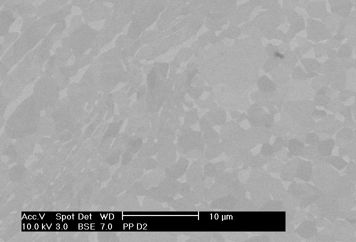
 through (b), the transition zone (c)")
, each at increasing magnifications in Specimen")
32 15e Figure 15 (a) (e): SEM BSE micrographs showing the stir zone (a) through (b), the transition zone (c) through (d) and interface of transition zone and base metal (e), each at increasing magnifications in Specimen D2. 16a 20


33 16b 16c 21

34 16d Figure 16 (a) (d): SEM SE micrographs showing the transition zone at increasing magnifications in Specimen #D5. Note secondary α nucleation in β -phase. Figures 15 and 16 are micrographs of the post-processing heat treatments performed on samples D2 and D5, respectively. D2 was heat treated at 815 o C for one hour, and D5 was heat treated at 730 o C for one hour. In figures 15b and 16b, it appears as though the equiaxed alpha particles are beginning to fuse together and are no longer individual grains; this is consistent with atoms diffusing from the β -regions into the α regions. A second observation is that there is a greater volume fraction of β seen in the stir zone of sample D2, heat-treated at 815 o C. The temperatures of both heat treatments are in the α + β phase field, but 815 o C is higher in the phase field, so this result is consistent with the findings. The as cast + HIP d microstructure at these temperatures is the colony microstructure as seen in figure 2. 22
35 Another important observation is that the transition zone appears to have become thinner after heat treatment. Figure 16a shows that the transition zone is about 50 microns deep. This is at most half as deep as the as-processed transition zone in figures 11 and 12. Lastly, there has been a significant amount of secondary α nucleation in specimen D5. This is not clearly seen in the micrographs taken from sample D2, heattreated at 815 o C. D5 was heat treated at 730 o C, and thus is expected to have an overall greater volume fraction of α at equilibrium. C. Appearance of Tungsten in processed and heat-treated samples Figures 15a and 15b are back-scatter electron SEM images showing very bright particles near the surface. The back-scattered electron images display heavier elements more brightly because they return more of the incident beam electrons to the Everhart- Thornley detector. The probable source of these particles will be outlined in the discussion, as well as the importance of their inclusion in the stir zone. 23

36 Figure 17. EDS spectra showing W peak taken from stir zone D. FIB 18a 24
 is of the lamellar base metal and shows shear bands.")
37 18b Figure 18 (a) (b): SEM SE micrographs of FIB results. (a) is of the lamellar base metal and shows shear bands. (b) is of the stir zone, and displays no shear bands. (2) 25
 These images clearly show the lack of texture, or the randomness of the orientations, of the equiaxed-α grains in the stir zone.")
38 OIM Figure 19. Orientation images of FIB sample showing no preferred orientation (2) These images clearly show the lack of texture, or the randomness of the orientations, of the equiaxed-α grains in the stir zone. The significance of the lack of texture in the stir zone will be discussed in detail in a future work; however, the lack of preferred orientation in the stir zone is desirable, as this is expected to inhibit fatigue crack initiation. 26
39 IV. Discussion A. Discuss why micro structural changes are occurring as a result of processing The initial purpose of this work was to assess the effect of FSP on the coarse lamellar as-cast structure. A secondary objective was to understand the effect of varying the FSP parameters such as the tool s translational speed, rotational speed, down force, and power would have on the resulting as-cast plate microstructure. The results presented in figures 10-14, and detailed examination to compare and contrast the samples produced using different processing parameters, show it is very difficult to see any significant differences in any of the microstructures as the result of varying the FSP parameters over the ranges used in this limited study. Every sample had an average equiaxed- α average diameter of about 1 µ m in the process zone. Any differences between average diameters would be very difficult to determine in a statistically valid way. Any effort to do such analysis lies outside the scope of this project. The key to understanding the mechanism that is controlling the conversion of the lamellar microstructure to the equiaxed-α microstructure lies in the observation of the transition zone. One major issue is whether or not the β -transus was exceeded during material processing. This is important because it will help to piece together everything else that is occurring while the tool is working the material. It is clear that the tool had to generate an enormous amount of heat during plastic deformation of the material, and that the rest of the material not involved in the direct stirring acted as a virtual infinite heat sink after the tool passed. It is also clear that the tool did an enormous amount of plastic 27
40 deformation to the material, as judged by the complete change in the microstructure. This also led to a large micro structural gradient in the transition zone. At the time of analysis of the micrographs, there are several observations that suggest the β -transus was not exceeded during processing. One in the transition zone is the size of the equiaxed-α particles in the stir zone. Another is the fine α -lamellae in the transition zone just adjacent to the stir zone. There is a very high volume percentage of α in the stir zone, but the maximum temperature attained in the stir zone would not have been maintained long enough time to permit β grain growth. Exceeding the β - transus would be expected to produce a greater volume fraction of β than was seen in figures 10a and 10b. The temperature-plastic strain relationships during FSP are, at best, complex and have not been adequately worked out. There are currently no suitable mechanistic models to account for these observations. B. Effect of micro structural changes on properties The micro structural changes that have occurred due to processing are expected to result in much better fatigue properties than the as-cast + H.I.P. material, based on experience with other wrought products of Ti-6-4. In fairness, there is little relevant experience with such fine-grained, random material, but there is no fundamental reason to anticipate a reversal of the wrought product trends. The life-limiting property in castings can be fatigue life, which currently is dominated by fatigue crack initiation of the coarse lamellar structure. The result of the friction stir processing is a very fine-grained equiaxed-α microstructure at the surface, with an average grain size of about 1 micron. This microstructure is stronger, based on the FIB pillar results. Consequently, it is 28
41 anticipated to be more resistant to fatigue crack initiation. Current work is continuing to demonstrate this point. Another very important feature of the post-processed microstructure is the elimination of grain boundary α. Elimination of grain boundary α is good for other properties. In particular, it is beneficial for tensile ductility and low cycle fatigue resistance because it minimizes micro structural sites that preferentially accumulate plastic strain during cyclic loading above the proportional limit. A. Effect of post-processing heat treatments on microstructure Post-processing heat treatments were performed on selected samples in order to get a better understanding of the amount of residual work left in the material. It also helps to elucidate the mechanism that controls the transformation from the lamellar microstructure to the equiaxed-α microstructure seen in the stir zone and to qualitatively assess the amount of residual stored work. One clue to this transformation is the presence of twisting and undulating α platelets in the transition zone of the microstructure. This suggests that there is residual strain energy in the material and that equilibrium was not achieved because of the very fast cooling rate of the FSP and the relatively severe deformation introduced by FSP. There is evidence that the microstructure is attempting to get back to its equilibrium lamellar form. One observation is the fusing of α particles as seen in figure 15a. Figure 15a also displays a greater volume fraction of β, which is consistent with heat-treating for an hour at 815 o C. 29
42 B. Observations of W in the microstructure The bright particles seen in figures 15a and 15b are tungsten or tungsten-rich particles as shown by EDS. These have most likely been embedded in the work piece by the tool, which is a W-Re alloy. The bright images in backscatter mode are consistent with the high atomic number. The presence of tungsten at the surface is undesirable for several reasons. First it means that portions of the tool are being lost to the work piece; this is a concern not only for the cost of having to replace the tool, but also for quality reasons that are associated with a tool that is contaminating the work piece. Another concern is the impact of tungsten on the mechanical properties of the processed casting. Tungsten has a significantly higher modulus than titanium, and is quite strong. Consequently theses particles can act as stress concentrators. This would lead to plastic strain gradients around the particles, which increases the probability of fatigue crack initiation. Lastly, tungsten is a strong β -stabilizer, so any subsequent heat treatment will produce β flecks. V. Conclusion A fine-grained equiaxed microstructure was produced by FSP using both sets of processing parameters. The overall microstructure of the as cast + HIP and FSP d pieces consists of fine equiaxed grains at the surface to inhibit fatigue crack initiation, and the original lamellar in the bulk to minimize fatigue crack growth. Post-processing heat treatments were conducted to gain a better understanding of the mechanism that converted the lamellar base metal to the equiaxed structure seen in the stir zone and to 30
43 assess the amount of residual work left by processing. A greater volume fraction of α was seen in the heat-treated samples. The strength and deformation behavior of the base metal and process zone was compared using the FIB to create pillars of the two microstructures. The base metal showed shear bands, consistent with the coarse colony structure, while the stir zone was free of shear bands. OIM was performed on the fine-grained stir zone and no evidence of preferred orientation (texture) was found. This also has the potential to improve fatigue crack initiation resistance. Micro structural analysis suggests that the β -transus was not exceeded during processing. Elimination of grain boundary α was seen as a result of processing. This also is a positive finding since it should enhance material performance. Tungsten was seen in the stir zone in several of the samples. This most likely comes from the tool used during friction stir processing. W is an unwanted form of contamination and the effects of it on material properties need to be assessed. VI. Future work More work needs to be done to gain a better appreciation of the factors responsible for the microstructure change from the coarse lamellar base metal structure to the equiaxed structure seen in the stir zone. OIM will be required to help understanding the texture seen in the stir zone. Fatigue tests need to be conducted to establish how fatigue resistant the fine-grained stir zone is. This is best done using four point bend tests that subject only the stir zone to maximum cyclic tensile stress. 31
44 VII. Bibliography 1) Boyer, R.R., Advanced Performance Materials. Volume 2, Number 4: ) Juhas, M.C., Pavka, P., Norfleet, D., Reynolds, T., Williams, J., The Effect of Friction Stir Processing on the MicroStructure and Strength of Cast Ti-6Al-4V. TMS conference presentation. 3) Juhas, M.C., Norfleet, D., Reynolds, T., Williams, J.C., Friction stir Processing of Ti-6Al-4V Castings. ONR Project Report # N ) Williams, J.C., Starke Jr., E. A., The Role of Thermomechanical Processing in Tailoring the Properties of Aluminum and Titanium Alloys. 32