Composite Materials. In depth look
|
|
|
- Benjamin Ball
- 5 years ago
- Views:
Transcription

1 Composite Materials In depth look


2 Classification of Composites Metals Materials Polymers Ceramics Composites Metal Matrix Composites Polymer Matrix Composites Ceramic Matrix Composites
3 Classification of Composites Two broad classes of composites: 1. Traditional composites composite materials that occur in nature or have been produced by civilizations for ages Examples: wood, concrete, asphalt 2. Engineering composites Synthetic material systems that are normally associated with the manufacturing industries The components are first produced separately and then combined in a controlled way to achieve the desired structure, properties, and part geometry
 allows better packing factor than when using particles of similar size.")
4 The most common traditional composite: Concrete Traditionally cement or volcanic ash are strengthened by adding particulates. The use of different size (stone and sand) allows better packing factor than when using particles of similar size. Concrete is improved by making the pores smaller (using finer powder, adding polymeric lubricants, and applying pressure during hardening.

5 Reinforced concrete: an engineering composite Traditional concrete is made even stronger under tensile and flexural shear stresses by adding steel rods, wires, meshes. Steel has the advantage of a similar thermal expansion coefficient, so there is reduced danger of cracking due to thermal stresses. Pre-stressed concrete is obtained by applying tensile stress to the steel rods while the cement is setting and hardening. When the tensile stress is removed, the concrete is left under compressive stress, enabling it to sustain tensile loads without fracturing. A common use is in railroad or highway bridges.
6 Secondary Phase, Reinforcement Typical engineering composites Primary Phase, Matrix Metal Ceramic Polymer Metal Powder metallurgy parts combining immiscible metals Cermets (ceramic-metal composite) Brake pads Ceramic Cermets, TiC, TiCN Cemented carbides used in tools Fiber-reinforced metals SiC reinforced Al 2 O 3 Tool materials Fiberglass in polyester Rubber with carbon (tires) Boron reinforced plastics Polymer Fiber reinforced metals Auto parts Aerospace PLA reinforced Calcium Phosphate Cements Kevlar fibers in an epoxy matrix


7 Typical reinforcements Function depends on matrix Metal matrix: to increase the hardness and creep resistance at high temperature Polymer matrix: to improve stiffness, and strength Ceramic matrix: to improve toughness
 Density Shock absorption Biocompatibility")
8 Typical reinforcements One reinforcement is common to all matrices: Air Voids are created in materials to improve many properties like Insulation (1/thermal conductivity) Density Shock absorption Biocompatibility Surface area
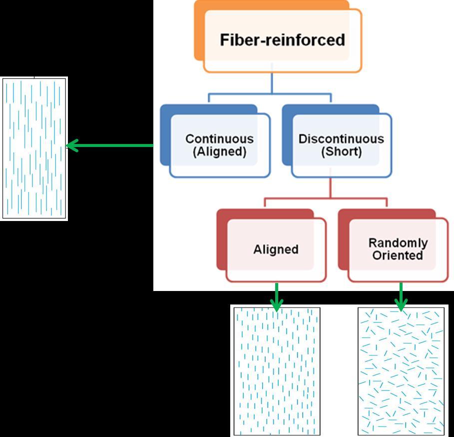
9 Classification of the reinforcing phase Composites can be engineered in terms of the amount, shape, size and distribution of the reinforcing phase, as well as the interface between the matrix and reinforcing phases Composites Particlereinforced Fiberreinforced Structural Large Particles Dispersion Strength Continuous (Aligned) Discontinuous (Short) Laminates Sandwich Panels Aligned Randomly Oriented
10 Composite types according to the reinforcing phase shape If the reinforcement is similar in all dimensions, it is a particulate reinforced composite If its shape is needle-shaped single crystals, it is whiskerreinforced composite If the reinforcement is cut continuous filament, it is chopped fiber-reinforced composite If the fiber is continuous, it is fiber composite. Possible physical shapes of imbedded phases in composite materials: (a) fiber, (b) particle, and (c) flake

11 Composite types according to the reinforcing phase shape For fiber composites, configuration gives a further category. It is a uniaxial fiber composite if fibers are aligned in one direction It is a laminar composite if fibers are arranged in layers It is a 3D woven composite if fibers are arranged in a threedimensional arrangement


12 Particle reinforced composites Very hard, small particles are dispersed generally to strengthen metals and metal alloys. The effect is like precipitation hardening but not so strong. Particles like oxides do not react so the strengthening action is retained at high temperatures. D particle > 100 nm d particle < 100 nm
13 Fiber reinforced composites


14 Structural composites Laminates are thin 3-dimensional composite plates with imbedded multidirectional or unidirectional fibers They can be thought of as sheets of continuous fiber composites laminated such that each layer has the fiber oriented in a given direction


15 Structural composites Sandwich panels are low density plates with honeycomb core -- benefit: light weight, large bending stiffness face sheet adhesive layer honeycomb
16 Reinforcements used in aerospace industry Flap support fairings Fwd segment (graphite/kevlar + non-woven Kevlar mat Aft segment (graphite/fiberglass) Ailerons (graphite) Engine strut fairings (Kevlar/fiberglass) Environmental control system ducts (Kevlar) Nose landing gear doors (graphite) Wing to body fairings (graphite/kevlar/fiberglass and Graphite/Kevlar + nonwoven Kevlar mat Aft flaps Outboard (graphite) Inboard (graphite/fiberglass) Tip fairings (fiberglass) Spoilers (graphite) Cowl components (graphite) Rudder (graphite) Auxiliary power inlet graphite Fixed trailing edge panels graphite /Kevlar + nonwoven Kevlar mat) Elevators (graphite) Fixed trailing edge panels upper (graphite /fiberglass), lower (graphite /Kevlar + non-woven Kevlar mat) Fixed trailing edge panels Graphite/Kevlar + non-woven Kevlar mat Wing leading edge lower panel Kevlar/fiberglass Body main landing gear doors (graphite) Trunnion fairings and wing landing gear doors (graphite/kevlar) Brakes( structural carbon)
17 Composite microstructure There is always an interface between constituent phases in a composite material. Most of the time the phases must bond where they join at the interface for the composite to operate effectively Interface: Zone across which matrix and reinforcing phases chemically, physically, mechanically interact Function: to transfer the stress from matrix to reinforcement Sometimes surface treatment is carried out to achieve the required bonding to the matrix Primary (matrix) phase Secondary (reinforcing) phase, fiber Interface
18 Composite microstructure In some cases, a third ingredient must be added to achieve bonding of primary and secondary phases Called an interphase, this third ingredient can be thought of as an adhesive. Primary (matrix) phase Secondary (reinforcing) phase, fiber Interphase (third ingredient) Interface

19 Composite microstructure Interphase may be composed of a solution of the primary and secondary phases at their boundary by diffusion
20 Composite properties depend on the microstructure properties of the matrix material, properties of reinforcement material, ratio of matrix to reinforcement, matrix-reinforcement bonding/adhesion, mode of fabrication determine the overall properties of the composite
21 Relations between the mechanical properties and structure The tensile strength σ, the elastic modulus in the direction of the load E, and the longitudinal strain ε L of a single phase material are obtained from the stress-strain response σ = Eε L The Poisson s ratio is obtained by measuring the contraction strain ε T across the sample υ = ε T ε L Since the sample contracts, ε T is negative and υ has a positive value less than 1.0 The shear modulus, G is related to E and υ by G = E 2 (1 + υ) The shear stress τ and shear strain γ are related by G: τ = G γ
22 Relations between the mechanical properties and structure In metal systems the material is generally assumed to be linear, isotropic, and elastic such that only a few tests are required to obtain basic tensile stiffness properties Only two values, the tensile modulus E, and the Poisson s ratio ν are required because of the small degree of anisotropy or symmetry of the metal microstructure Metals have an infinite number of symmetry planes In contrast a material with no symmetry planes requires 21 material properties and extensive testing in order to design a structure Most composites are developed in two dimensional form and have one plane of symmetry
23 Relations between the mechanical properties and structure For example a laminate plate is a unidirectional material and is transversely isotropic The stress-strain law governing this material is complicated as there are 5 material properties (σ,τ,ε,γ,e) Stress-strain law for metals: For laminate composite: σ 1 σ 2 σ 3 τ 23 τ 31 τ 12 = σ = E ε E 11 E 12 E 12 E 22 E 23 E 22 Sym (E 22 E 23 ) 0 0 E 66 0 E 66 ε 1 ε 2 ε 3 γ 23 γ 31 γ 12 Where E 22 = E 33, E 12 = E 13 = E 11 /υ 12 = E 22 /υ 21, E 22 = E 22 /υ 23, 1 E 55 = 1 E G 12
24 Relations between the mechanical properties and structure E 11 is determined from a tensile test conducted in the direction of the fiber orientation The value of Poisson s ratio, ν 12 is obtained by measuring the lateral contraction strain E 22 is determined by cutting a laminate to pull it in tension transverse to the fiber direction The value of Poisson s ratio, ν 21 is obtained by measuring the lateral contraction strain but its value will be much less than ν 12 due to fiber constraint Measuring ν 23 is hard. It is small and usually ignored because most composites are two dimensional (It is the ratio of the strain across the fibers relative to the thickness strain) The value of G 12, the shear modulus is measured using simple circular tubes of the material. The tubes are twisted and the resultant shear stress and strain are determined
25 Relations between the mechanical properties and structure The values of longitudinal modulus E 11, principle Poisson s ratio ν 11, and principle thermal expansion coefficient α 11 can be expressed in terms of the matrix/fiber properties and the volume fraction of the respective ingredients according to the rule of mixtures: E 11 = V f E f +V m E m ν 11 = V f ν f + V m ν m α 11 = V f α f + V m α m Certain assumptions are made to relate the microstructure of the ingredients to these properties: The composite ply is macroscopically homogeneous and linearly elastic The fibers are linearly elastic and homogeneous The matrix is linearly elastic and homogeneous Both the fiber and the matrix are free of voids The interface is completely bonded and there is no interphase between the matrix and reinforcement The mechanical properties of the individual constituents are the same whether they are made before or during the composite manufacturing process

26 Relations between the mechanical properties and structure The upper bound is found by assuming that the two components strain by the same amount, like springs in parallel E 11 = V f E f +V m E m The lower bound is found by assuming that the two components carry the same stress, like springs in series E f E m E 11 = V f E f +V m E m


27 Relations between the mechanical properties and structure Cellular solids are characterized by their relative density, the fraction of the foam occupied by the solid ρ foam ρ s = t L 2 E foam E s = ρ foam ρ s 2
28 Relations between the mechanical properties and structure In a composite material with a metal matrix and ceramic fibers, the bulk of the mechanical energy would be transferred through the matrix. In a composite consisting of a polymer matrix containing metallic fibers, the energy would be transferred through the fibers. For example, in a metal fiber-polymer matrix composite, coefficient of thermal expansion would be low and would depend on the length of the fibers, the volume fraction of fibers and how often the fibers touch one another. Example You have a unidirectional, graphite/epoxy composite with the following constituent properties and 65% volume loading of fiber: E f = 43 GPa, E m = 0.5 GPa ν f = 0.2, ν m = 0.4 α f = 1.5*10-6 /K, α f = 40*10-6 /K Calculate the E 11, ν 11, and α 11 using the rule of mixtures