Fusion Bonded Joint: An innovative technology for cost efficient plastic-lined pipe installation and operation
|
|
|
- Jennifer Hill
- 5 years ago
- Views:
Transcription


1 efficient plastic-lined pipe installation and operation Qualification Campaign MCE Deepwater Development 2015, London

2 Introduction Corrosion: key issues for subsea flowlines Current solutions Corrosion allowance Internal cladding with Corrosion Resistant Alloy Internal plastic liner Internal plastic liner technology limited to reeling so far The FBJ offers a cost effective method for J-laying Corroded Water Injection Flowline (COREL JIP) 2
3 Agenda Requirements of the technology Overview of the Joint technology Fabrication and Installation Overview of the qualification tests Conclusion 3
4 Overview of the FBJ Overview of a Plastic lined pipe for J-lay Onshore Quad Joint are assembled Plastic liner is inserted Offshore Plastic liner is going to be damaged during offshore welding Cut back length on liner is created Taylor designed sleeve in inserted to ensure continuity of liner?? 4
5 Requirements of the technology Excellent sealing properties No impact on Flow Assurance / Piggability Low marginal cost Limited impact on offshore operations Conventional carbon steel weld 5

6 Overview of the FBJ HDPE sleeve is inserted at the weld location Electro-fusion weld between sleeve and liner Based on technology applied for over 20 years onshore FBJ before first application of pressure Smooth constant ID: Preserves piggability Fully controllable through AUT Fully repairable FBJ under pressure 6

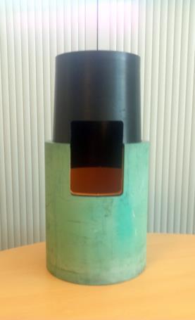
7 Overview of the FBJ 7


8 Overview of the FBJ Electro-fusion welding Development of dedicated tool ICS: Inflatable Clamping System AUT Probe Functions Maintain FBJ in position Ensure good face mating Power supply for EF Support AUT probes Two versions Horizontal Vertical Controlled using a graphical interface Light Equipment ~5 kg No lifting equipment needed Pull Back System Welding Contactor Clamping System ICS installed on FBJ Clamping System 8

9 Fabrication and Installation Onshore Joints are assembled into quadjoints (~50 m) HDPE liner is inserted in the quad joints Liner extremities are machined to specified tolerances -5 to 10 mm Offshore Carbon steel pipe is beveled HDPE final machining is performed FBJ is installed in the firing line QJ is transferred to the tower Final assembly in the J-lay tower Pipe face mating prior to welding (Offshore) 9
10 Development steps The FBJ Technology: Development steps Step 1 FBJ fabrication in HDPE Complete electrical design test Completed in 2012 Step 2 Fusion Bonding tests with pipeline Pulling Destructive testing without pipeline Design and fabrication of ICS Completed in 2013 Step 3 Design and fabrication of Machining tool Carbon Steel Welding testing on lined samples Completed in 12/2014 Step 4 Resonant Fatigue testing under pressure Planned for 04/


11 Step 2 Electro-fusion process qualification Goals of the step Design and Fabrication of the ICS Qualify Electro-Fusion Process Findings Electrofusion is a very sturdy process All welds successfully pressure tested Strength of HDPE unaffected by welding process 11
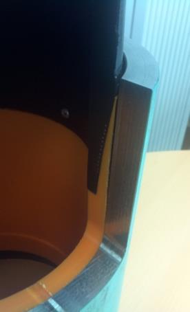
12 Step 2 Electro-fusion process qualification 12


13 Step 3 Complete process qualification Goals of the step Fabricate the liner machining tool Qualify the use of the ICS and FBJ In a totally enclosed environment In an environment as representative as possible of the one of the FDS Qualify the carbon steel weld in the presence of the FBJ Carbon Steel Welding Performed tests Standard welding of the CS pipe with temperature monitoring Shrinkage effect Temperature gradient in FBJ pipe Verification of the root pass quality Fabrication of 5 fatigue strings Electro-Fusion NDT 13


14 Step 3 Complete process qualification Liner Machining Tool 2 Steps Machining Cylindrical head Remove most of the liner Conical head Adjust dimension for fit up 15 minutes for complete machining Cylindrical Machine Head Machining Tool Conical Machine Head 14

15 Step 3 Complete process qualification VIDEO QUALIFICATION CAMPAIGN 15

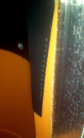
 Liner Machining Tools Over 50 machined pipe ends without any issue Improvement of associated tools HDPE Sleeve after")
16 Step 3 Complete process qualification Carbon Steel Welds Standard Welding parameters Continuous Welding process All welds were found acceptable under MUT and RT Electro-Fusion Welds Vertical and horizontal ICS fully functional NDT of plastic welds didn t show any issue in the welds Root Pass Examination Interaction between FBJ and CS weld No impact on line-up No impact on Carbon Steel weld No impact on FBJ sleeve (Temperature below 120 C at all time) Liner Machining Tools Over 50 machined pipe ends without any issue Improvement of associated tools HDPE Sleeve after welding 16


17 Step 4 Fatigue testing Targets Confirm quality of carbon steel welds (Class D Curve) Demonstrate HDPE fatigue life > Carbon steel fatigue life Program 2 Stress levels: 200 & 150 MPa 4 Welds per level 1 Spare string Stress level monitored both in Carbon Steel and Plastic Welds Fatigue Strings ready for expediting Specificities Specific End Piece design to detect origin of leak Prevent water ingress outside of weld location Fatigue Testing 17
18 Conclusion FBJ is nearing full qualification Sleeve manufacturing process validated Electro-fusion welding paramters validated Carbion Steel welding process qualified Fatigue performance of the weld assessed within 2 weeks FBJ appears as a sturdy technology Plastic welding process very tolerant to parameters Carbon Steel welding process unaffected by sleeve presence Sleeve unimpacted by Carbon Steel welding process 18