ME 7502 Lecture 1 Introduction to Composite Materials and Composite Structures
|
|
|
- Kelley Tate
- 5 years ago
- Views:
Transcription
1 ME 7502 Lecture 1 Introduction to Composite Materials and Composite Structures Definitions Particulate Composites Laminated/Lamellar Composites Fiber Composites Fiber Composite Manufacturing Processes Applications of Composite Material and Structures Composite Material/Structural Design Process Matrix Algebra MathCAD 1
2 COMPOSITE MATERIAL: MATRIX PHASE: DEFINITIONS A MATERIAL SYSTEM COMPOSED OF TWO OR MORE DIFFERENT, INSOLUBLE MATERIAL PHASES A MATERIAL PHASE CONTINUOUSLY CONNECTED TO ITSELF INCLUSION OR REINFORCEMENT PHASE: A MATERIAL PHASE COMPLETELY SURROUNDED BY MATRIX WHICH USUALLY APPEARS AS MANY DISCRETE UNCONNECTED GEOMETRICAL PARTS PHASE VOLUME FRACTION v p = vol. of phase/total vol. PHASE WEIGHT FRACTION w p = wt. of phase/total wt. VOLUME WEIGHT v i = inclusion vol. fract. v f = fiber vol. fract. v p = particle vol. fract. v m = matrix vol. fract. v/o = volume percent w i = inclusion wt. fract. w f = fiber wt. fract. w p = particle wt. fract. w m = matrix wt. fract. w/o = weight percent 2

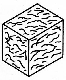
3 TYPES OF COMPOSITES PARTICULATE UNIDIRECTIONAL FIBER SHORT FIBER FLAKE FILLED LAMINAR/LAMINATED 2-D WOVEN 3-D WOVEN BRAIDED 3
4 PARTICULATE COMPOSITES INCLUSIONS HAVE 3 DIMENSIONS ON SAME ORDER OF MAGNITUDE DISPERSION-HARDENED METALS METAL (Al, Steel)/POLYMER - INCREASE ELECTRIC/THERMAL CONDUCTIVITIES METAL/CARBON - RESISTORS CERMETS (CERAMIC INCLUSION/METAL MATRIX) - UP TO 30% V M Al 2 O 3 /Cr LOW MOLTEN-METAL-WETTING, LOW FRICTION, MgO/Cr RESIST THERMAL SHOCK, EROSION, ABRASION, FLAME, HIGH THERMAL CONDUCTIVITY W Carbide/Co, Cr Carbide/Co, Ti Carbide/Co FILLER/POLYMER Ca Carbonate, Clay Glass µ spheres Carbon/Rubber GOOD RESISTANCE TO ABRASION, IMPACT, USED IN MOLTEN METAL FLOW GUIDES, WIRE DIES, PRECISION ROLLS, GAGES, VALVE PARTS, CUTTING TOOLS LOW COST, HIGHER STIFFNESS MOLDED ITEMS, AUTO PARTS 4
 -CERAMIC/METALS, CERAMIC/CERAMIC (CORROSION,")
 METAL (Al, Iron) AlB 2 GRAPHITE HIGHER E, K, Strength, etc.")
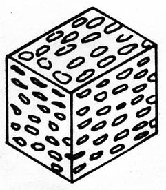
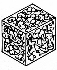
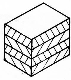
5 LAMINATED/LAMELLAR COMPOSITES REINFORCING PHASE HAS ONE DIMENSION MUCH SMALLER THAN THE OTHER TWO LAMINATED -METAL CLAD/COATED METALS Al/U Ti/Steel Cu/W Al/Be Ni, Cu, Al, Au, Ag, Sn, Pb/Mo (Electrical, Chemical, Thermal Applications) -CERAMIC/METALS, CERAMIC/CERAMIC (CORROSION, HEAT-RESISTANT) -PAPER/POLYMER -LAMINATED UNIDIREC. & WOVEN LAMELLAR FLAKE / MATRIX GLASS METAL POLYMER (EPOXY, PHENOLIC, POLYESTER) METAL (Al, Iron) AlB 2 GRAPHITE HIGHER E, K, Strength, etc., THAN MATRIX, GREATER PACKING DENSITY THAN PARTIC., LOWER COST THAN FIBERS Gr/Ep AlB 2 flake 5
6 FIBER COMPOSITES FIBER GLASS GRAPHITE/CARBON BORON SiC +MATRIX LAMINATE UNIDIRECTIONAL OR WOVEN, STACKED MULTIDIRECTIONALLY OXIDE SHORT FIBER CHOPPED FIBER 1/4-2 CONTINUOUS FIBER FILAMENT - SINGLE STRAND ROVING ENDS TOW - 1,000-10,000 ENDS, NOT TWISTED YARN - 1,000-10,000 ENDS, TWISTED 6
 SMC-R30 (b) SMC-C40 R30 (c) XMC SMC-R SHEET")

 BMC - BULK MOLDING COMPOUND -")
7 SHORT FIBER COMPOSITES SHORT (25 mm) FIBERS + FILLER + RESIN (a) SMC-R30 (b) SMC-C40 R30 (c) XMC SMC-R SHEET MOULDING SMC-CR XMC COMPOUND FIBERS 25-30% W SMC-R + SMC-CR, BUT RESIN 30% W CONTINUOUS FIBERS CONTINUOUS FILLER 40-45% W ±5-7 SHEET FORM HMC - STRUCTURAL GRADE SMC (60-65% W FIBERS) BMC - BULK MOLDING COMPOUND - SMC IN BULK FORM 7
8 HIGH-PERFORMANCE FIBER COMPOSITES MULTIDIRECTIONAL, CONTINUOUS FIBER COMPOSITE FIBER PHASE GLASS GRAPHITE (CARBON) BORON ARAMID (KEVLAR) CERAMICS - SiC - OXIDE MATRIX PHASE POLYMERS CERAMICS METALS TOW (1 K -10 K ENDS) TAPE FILAMENT WINDING ROVING (~100 ENDS) YARN (TW 1 K -10 K ENDS) WOVEN FABRIC BRAIDED PREFORM 3-D WOVEN PREFORM 8


9 BORON TAPE WOVEN GLASS ROVING BRAIDED PREFORM KEVLAR 49 TOW 9
10 TAPE OR THERMOSET + PREPREG FABRIC RESIN (PMC) TAPE OR FABRIC + (CMC) CERAMIC MATRIX PLY STACKING FIBER COMPOSITE LAMINATE (PMC) TOW + RESIN FILAMENT WINDING -HIGH STRENGTH -LOW WEIGHT -HIGH STIFFNESS -TAILORABILITY OF THERMO-MECHANICAL PROPERTIES -GOOD FATIGUE CHARACTERISTICS -CMCs : EXCELLENT HIGH TEMPERATURE APPLICATIONS 10

![[0/0/+45/-45] = [0 2 /+45/-45] COMMON LAY-UPS : [0 i /±45 j /90 k ] s ; [0 i /±θ j ]](/docs-images/89/98426256/images/11-1.jpg "[0/+45/-45/-45/+45/0] [0/±45] S OR [0 2 /±45] S - BENDING, TORSION [0 /±45/90] S - [0/±60] S -")
11 FIBER COMPOSITE LAMINATE - INDIVIDUAL PLY MAY BE UNIDIRECTIONAL OR WOVEN STACKING SEQUENCE/PLY LAY-UP SYMMETRY [0/+45/-45/-45/+45/0] = [0/+45/-45] S REPEATED SEQUENCE [0/90/0/90] = [0/90] 2 [0/0/+45/-45] = [0 2 /+45/-45] COMMON LAY-UPS : [0 i /±45 j /90 k ] s ; [0 i /±θ j ] [0/+45/-45/-45/+45/0] [0/±45] S OR [0 2 /±45] S - BENDING, TORSION [0 /±45/90] S - [0/±60] S - QUASI-ISOTROPIC 11

12 FIBER COMPOSITE MANUFACTURE THERMOSET MATRIX, CONTINUOUS FILAMENTS Manual Lay-up... -APPLY GEL COAT, FIBERS, RESIN -POSITION PREPREG -APPLY FIBERS / WOVEN FABRIC, INJECT RESIN...+cure -FREE CURE (R.T. THERMOSETS) -VACUUM BAG OR PRESSURE BAG, THEN AUTOCLAVE ( F, psi) -COLD PRESS MOLDING (RT) OR -MATCHED METAL DIE COMPRESSION MOLDING ( F, psi) 12
13 Filament Winding Sheet Continuous Lamination Pultrusion 13


14 THERMOSET MATRIX, SHORT FIBERS Manual Lay-up of Prepreg, Cure Sheet Continuous Laminating Spray-Up 14
 Liquid Wetting -Liquid Metal Infiltration of Fibers -Heat Powder & Fibers above Matrix Solidus Deposition -Matrix")
15 THERMOPLASTIC MATRIX Pultrusion (Continuous Filaments) Injection Molding (Short Fibers) Extrusion Hot Forming (Preformed Sheets) METAL MATRIX Diffusion Welding -Press/Sinter Matrix Powder, Bare/Coated Fibers -Press Coated Fibers -Press Fibers between Foil (+Powder) Liquid Wetting -Liquid Metal Infiltration of Fibers -Heat Powder & Fibers above Matrix Solidus Deposition -Matrix electrodeposition, Vacuum deposition, or Plasma Spray onto Fibers, Press 15

16 RESIN MATRIX PROCESSES Hand Layup Vacuum Bag Layup 16
17 RESIN MATRIX PROCESSES (cont d) Pressure Bag Molding Auto-clave Molding 17
18 RESIN MATRIX PROCESSES (cont d) Out-of-Autoclave Composite Manufacturing offers Reduced recurring costs Reduced cycle times for primary structures Potential improvements in quality by reducing pressure and resin flow Utilizes resins specifically engineered for lower pressure, lower temperature cures Can enable manufacture of some very large primary composite structures Co-cures of separately fabricated parts facilitated by successful out-of-outclave manufacturing 18
19 RESIN MATRIX PROCESSES (cont d) Out-of-Autoclave Composite Manufacturing methods include: Vacuum Bag Only Resin Transfer Molding (RTM) Vacuum Assisted Resin Transfer Molding (VARTM) Balanced Pressure Fluid Molding Microwave Curing Prepreg compression molding E-Beam Curing 19
20 Ceramic Matrix Composite Processes 3 Main Types: a. Chemical Vapor Infiltration (CVI) 1) Requires extensive facilitation (furnaces to deposit chemical composition of matrix phase through vapor infiltration) 2) Results in the fabrication of high quality CMC parts 3) Very economical process for large lots of parts but not inexpensive for small lots b. Polymer Infiltration and Pyrolysis (PIP) 1) Facilitization requirements are not as extensive matrix infiltration is very similar to OMC parts 2) Parts are usually of lower quality than CVI parts 3) Economical for small lots of CMC parts quite costly for large lots of parts c. Melt Infiltration (MI) 1) Requires special high temperature furnaces to melt silicon metal being infused into the prepreged composite 2) Parts can be very high quality 3) Process has not yet been used for large lots of parts; currently cost lies between CVI and PIP 20
21 C/SiC Overview Attributes 3000F + Temperature Capability High Specific Strength Non-Oxidizing Matrix Matrix CTE Compatible with EBC High Durability with EBC Coating Environmental Barrier Coating C Fiber Fiber/Matrix Interface Coating SiC CVI Matrix C/SiC 21


22 C/SiC Microstructure Photomicrograph from A. Calomino NASA GRC 22
23 C/SiC Manufacturing Process Customer Design Customer CTQ s Composite Design Tooling and Process Design C/SiC C Fiber Pan or Pitch Textile Processes 2D/3D Heat Treat and Prepreg Preform Lay-up & Tooling Autoclave Machining Inspection CVI Carbon Fiber Interface CVI SiC Densification CVI SiC Protective Coating 23


24 Preforming Capability Fabric Cutters Autoclaves Heated Presses 24

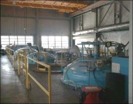
25 CVI Reactors 25


26 CMC Machining Capability HAAS VFZ Mill, 4-Axis CNC Weldon CNC Cylindrical Grinder HAAS VR II Mill, 5-Axis CNC 26


27 CMC Analysis, Testing & Inspection Capability IR NDE SEM Optical Microscopy CMM Mechanical Testing 27

28 C/SiC Manufacturing Process Customer Design Customer CTQ s Composite Design Tooling and Process Design C/SiC C Fiber Pan or Pitch Textile Processes 2D/3D Heat Treat and Prepreg Preform Lay-up & Tooling Autoclave Machining Inspection Tooling may CVI Carbon Fiber Interface CVI SiC Densification CVI SiC Protective Coating be required 28


29 Preform Tooling Required: All Parts Types: Similar to Polymer Matrix Composites Materials Metals, Graphite, Plastic Design Concerns CTE, Debulk Pressure, Assy/Disassy Release Applied Vacuum Debulk Preform Layup 29


30 CVI Tooling Required: During CVI PyC and 1 st CVI SiC Types: Perforated Graphite Materials Purified Graphite Design Concerns CTE, Preform Pressure, Assy/Disassy 30
 Prepreg: Fugitive Binder as a Manufacturing Aid (MS5007000) 50 yard rolls of fabric ready for Heat Treatment")
31 Fabric Descriptions 2D Fabric Balanced Plain Weave (MS ) T300 1K Tow (MS ) Heat Treat: Maximum Use Temperature (MS ) Prepreg: Fugitive Binder as a Manufacturing Aid (MS ) 50 yard rolls of fabric ready for Heat Treatment 31


32 Fabric Descriptions Draping 2D Fabric Draping analyses performed on complex shapes Shear maps used for ply design and layup Plain weaves shear < satin weaves T.E.A.M. Inc. textile engineering and manufacturing Combustor Liner Draping Analysis Combustor Liner Preform 32


33 Fabric Descriptions 3D Weave Orthogonal, Angle and Layer Interlock Constructions T300 1K and 3K Pros: Can bias reinforcement No delaminations Cons: Size limitations due to limitations in weaving equipment Inplane property knockdown with minimal across-ply property improvement Orthogonal Angle Interlock Layer Interlock Angle Interlock Fill View 33


34 Fabric Descriptions Braids 2D Braids 3D Braids: Cartesian and Lockstep Processes T300 3K max (CVI Requirement) Pros: Can conform to complex geometries Cons: Size limitations due to limited number of braiding carriers 2D Flat Braid 2D Triaxial Braided Thruster and close-up of throat prior to machining 34
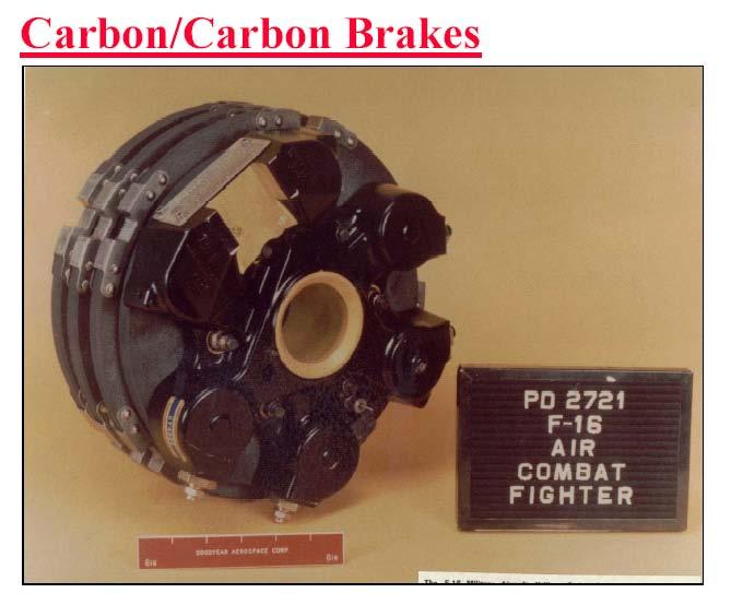
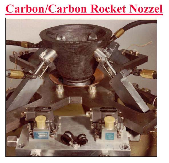
35 Types of Ceramic Matrix Composites and their Applications Most common is carbon fiber reinforced carbon matrix (C-C) aircraft brakes, rocket nozzles Carbon fiber reinforced silicon carbide matrix (C/SiC) Space Shuttle TPS repair parts, rocket motor thrusters Silicon carbide reinforced silicon carbide matrix (SiC/SiC) jet engine (flaps and seals, combustor liners) and turbine engine components (stator vanes) 35
36 36
37 37


38 Space Shuttle Return to Flight Plug Repair Concept Description Flexible 7-in MCM-700 coated C/SiC cover plates Cover plates flex and conform to WLE within 0 to 5 mils TZM attach hardware coated with R512E and MCM to 30 unique plug geometries required to provide coverage of all WLE panels to within 1 of T-seals Uncured NOAX edge sealant is being developed for edge gaps exceeding 20 mils Capable of repairing RCC damage with a maximum dimension of 6 C/SiC Cover Plate Flexes to Conform to WLE TZM Attach Hardware C/SiC Cover Plate Status 13 Plug Repair Panels on ISS 6 additional Plug Repair Panels by 7/06 Inserting Plug Assembly Back View of Installed Plug Assembly 38


39 Aft end of the engine for the F-18 Super Hornet showing CMC flaps and seals after 500 sorties in Iraq War 39
40 CONSTITUENT & COMPOSITE PROPERTIES THERMOSETS MATERIAL EPOXY to 250 F POLYIMIDE to 600 F THERMOPLASTICS ACRYLIC POLYESTER ABS* CERAMICS ALUMINUM OXIDE (Al 2 O 3 ) SILICON CARBIDE (SiC) OTHER ALUMINA MATRIX PROPERTIES (R.T.) UTS (kpsi) ρ (pci) E (Msi) α (µ F -1 ) UCS (kpsi) y Y Y Y STEEL (1040) (YP) 6 ALUMINUM (7075-T6) (YP) 13.3 GLASS (1/2 in. ROD) GRAPHITE (BULK) *ACRYLONITRILE BUTADIENE-STYRENE
41 FIBER PROPERTIES (R.T.) MATERIAL ρ (pci) E (Msi) UTS (kpsi) α (µ F -1 ) E-GLASS S-GLASS ARAMID-KEVLAR KEVLAR GRAPHITE (TYPICAL) BORON * 530* 2.7 ALUMINUM OXIDE (Al 2 O 3 ) SiC
42 COMPOSITE PROPERTIES FILLED EPOXY RESINS (PARTICULATE) FILLER w i, w/o E (Mpsi) S UT (ksi) S UC (ksi) NONE SOLID GLASS SPHERES CaCO 3 CLAY SMC (SHORT [0.5-2 in] FIBER/POLYESTER MATRIX) FIBER v f v/o E 1 (Mpsi) S 1ut (ksi) (E 2 ~ 0.8E 1 ) GLASS (S 2ut ~ 0.8S 1ut ) CARBON GLASS, 24, CARBON
43 FIBER COMPOSITE PROPERTIES v f = 0.6 [0] UNI. E 1 (Mpsi) E 2 (Mpsi) S 1 t (kpsi) S 1 c (kpsi) S 2 τ S2-GL/EP HM GR/EP KEV 49/EP B/EP [0/±45/90] Q/I E x (Mpsi) S x t (kpsi) ρ w (pci) S2-GL/EP HM GR/EP KEV 49/EP B/EP [0/90] E x /ρ w (M*in) S x t / ρ w (k*in) S2-GL/EP H GR/EP KEV 49/EP B/EP STEEL T6 AL
44 COMPARISONS [0/90] FIBER/EPOXY, V f = HM GR/EP S2-GL/EP KEV 49/EP B/EP S UT / ρ (M*in) T6 AL 1040 STEEL E x / ρ (M*in) 44
45 COMPARISONS 180 Strength Vs. Temperature Strength (ksi) Steel 3D-Pitch Carbon-Carbon Temperature ( F) 45
46 SUMMARY GL/EP: GOOD STRENGTH/WEIGHT, CHEAP, NON-CONDUCTING (ELECTRICITY) LOW STIFFNESS/WEIGHT GR/EP: GOOD STRENGTH/WEIGHT, STIFFNESS/WEIGHT, ZERO AXIAL THERMAL EXPANSION, EXPENSIVE, FLAMMABLE, CONDUCTS ELECTRICITY KEV49/EP: GOOD TENSILE STRENGTH/WEIGHT, IMPACT RESISTANT, MODERATE COST ZERO AXIAL THERMAL EXPANSION, POOR COMPRESSIVE STRENGTH, MODERATE STIFFNESS/WEIGHT B/EP: GOOD STRENGTH/WEIGHT, STIFFNESS/WEIGHT, OUTRAGEOUSLY EXPENSIVE HYBRIDS: COMBINE REINFORCEMENT LAYERS TO ADVANTAGE CMC: EXCELLENT HIGH TEMPERATURE STRENGTH, HIGH CORROSION RESISTANCE 46