COMPRESSION TESTING USING A CAM-DRIVEN ELECTROMAGNETIC MACHINE
|
|
|
- Lilian Francis
- 5 years ago
- Views:
Transcription


1 COMPRESSION TESTING USING A CAM-DRIVEN ELECTROMAGNETIC MACHINE Carlos Silva, Pedro Rosa and Paulo Martins Instituto Superior Técnico, TULisbon, Portugal

2 Introduction This paper presents a low-cost, cam-driven, electromagnetic machine for the compression testing of materials under different rates of loading (medium to high rates) that is flexible to adjust its kinematics in order to follow the strain-rate vs. strain path of a specific process. The equipment was designed, fabricated and instrumented by the authors and the flexibility and adequacy of its operating conditions are shown by determining the mechanical behaviour of Aluminium AA1050-O and technically-pure Lead under different testing conditions.


3 Equipment Overview The cam-driven electromagnetic testing machine consists of an electromagnetic actuator, a fixed housing containing two flat compression platens, a translating cam and a follower. Compression platens Translating cam. The electromagnetic actuator makes possible reaching high strain rates with a very precise control of the impact velocity and of the energy transmitted to the translating cam.


4 Equipment Translating cam and follower The cam profile enables synchronizing the performance of the testing machine with that of the machine-tool where manufacturing will take place. The follower traces the cam profile and converts x-movement of the ram to y-displacement of the lower compression platen. Compression platens Load cell Lower compression platen Follower Vy Vx Cam Profile Test specimen Eddy-current displacement sensor
5 Equipment Cam profile and pressure angle Logistic cam: Entry dwell followed by a rise contour and a final dwell towards the uppermost profile of the cam Root-type cam: Sharp rise at the entry followed by a dwell towards the uppermost profile of the cam The translating cam and the follower were made from steel DIN 14NiCr14 and DIN 100Cr6. The clearance fit for the cam-follower system is H7/f7 (ISO). Final manual grinding and polishing was necessary to eliminate small surface errors and imperfections.
6 Equipment Kinematics Vy Vx v y = dy dt = v x dy dx v avg x dy dx Logistic cam a y = dv dt y
7 Equipment Kinematics Vy Vx v y = dy dt = v x dy dx v avg x dy dx Root-type cam a y = dv dt y


8 Equipment Electromagnetic actuator The electromagnetic actuator consists of electrical circuits for charging and firing the banks of energy-storage capacitors (each with 6 mf) and a series of coils that generate the pressure to accelerate the ram linked to the translating cam. Typical coils with eight windings, a total length of 92 mm, an external diameter of 160 mm and an internal diameter of 70 mm, were utilized. The ram consists of a long and heavy bimetallic bar made of AA 6082-T651 Aluminium with slotted A 1000 V Disjuntor 60? / 70 W Diodo Tiristor Relé hollow half-ring surface inserts (to reduce eddy current V 450 V 12 V 500 ma losses) of DIN St52.3 Steel. A V 0-100% V A A Mosfet ~ 230 V V V 12 V 500 ma A V A V


9 Equipment Targeted performance The cam-driven electromagnetic machine is expected to enable mechanical testing of materials to be performed under the strain-rate vs. strain loading paths that are commonly found in manufacturing in order to meet the machine-tool and process combined requirements. Hopkinson bar ~ 10 3 to 10 4 s -1 (refer to blanking) Drop weight system ~ 1 to 10 3 s -1 (refer to forging)
 Case Testing Conditions Vx (m/s) 1 Quasi-static 0.01 7 Root type cam profile 3.5 2 Logistic cam profile 4 8 Root type cam profile 7 3 Logistic cam profile 3.")
10 Experiments Aluminium AA1050-O The stress-strain curve was obtained by means of upset compression tests on cylindrical specimens with 6 mm diameter and 6 mm height. Case Testing Conditions Vx (m/s) Case Testing Conditions Vx (m/s) 1 Quasi-static Root type cam profile Logistic cam profile 4 8 Root type cam profile 7 3 Logistic cam profile Root type cam profile Logistic cam profile Root type cam profile 14 5 Logistic cam profile Root type cam profile Logistic cam profile 9.2 No saw tooth oscillations are observed when a logistic cam is utilized due to the smooth transition between the entry dwell and subsequent profile and to the value of the maximum pressure angle.
11 Three-dimensional flow surface Aluminium AA1050-O The three-dimensional flow surface in which stress, strain and strain-rate are the leading axis results from fitting experimental data to the following mathematical material model that was developed by the authors n h v y D, m, C = 0 σ = B ε = ln 0 ( A + ε ) ε = h mε n ( A + e ε ) B + C ln[ + ε ] ( ) σ = D h D, n, C = 0 σ = B + mε ( A e ) n C ( A + ε )( B ln ε ) D, n = 0 σ = + (Ludwik-Holloman) (Voce) (Johnson-Cook) The material model has the ability for exhibiting material flow softening at high values of strain. Flow softening is responsible for diminishing the resistance to plastic deformation and is known to cause a significant influence in the deformation mechanics of metal cutting, namely chip formation. The three-dimensional flow surface that results from fitting experimental data to the material model is shown in the next slide.
 Aluminium AA1050-O")
 Strain-rate (s-1) Strain")
12 Three-dimensional flow surface Stress (MPa) Aluminium AA1050-O Strain Stress (MPa) Strain-rate (s-1) Strain-rate (s-1) Strain
13 Three-dimensional flow surface Aluminium AA1050-O The differences between the flow surfaces obtained from material testing with logistic and root type cams are made clear by analysing a selection of intersections of the three-dimensional flow surfaces with constant strain-rate planes. The flow curves resulting from these intersections indicate that major differences are due to flow softening.
 Case Testing Conditions Vx (m/s) 1 Quasi-static 0.01 7 Root type cam profile 3.7 2 Logistic cam profile 2 8 Root type cam profile 7.2 3 Logistic cam profile 3.")
14 Experiments Technically-pure Lead The stress-strain curve was obtained by means of upset compression tests on cylindrical specimens with 6 mm diameter and 6 mm height. Case Testing Conditions Vx (m/s) Case Testing Conditions Vx (m/s) 1 Quasi-static Root type cam profile Logistic cam profile 2 8 Root type cam profile Logistic cam profile Root type cam profile Logistic cam profile Root type cam profile Logistic cam profile Root type cam profile Logistic cam profile Hopkinson bar 3.2 Stress (MPa) Stress (MPa) Strain-rate (s -1 ) Strain-rate (s -1 ) Strain Strain
15 Machine tool and process requirements Metal cutting 1'' 1''' 1' 2'' 2''' 2' 3'' 3''' 1 2 3' 4' 4''' 4'' (ε'', ε'') (ε', ε') (ε''', ε''') 3 φ 4 (ε, ε)


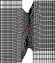
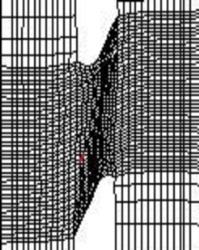
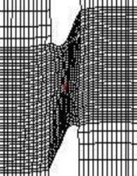


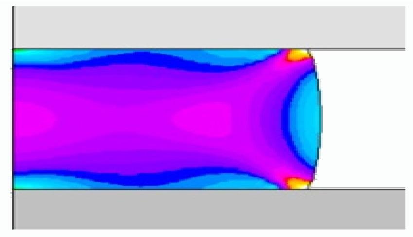
16 Machine tool and process requirements Blanking and shearing Center Boundary Element 1 Element


17 Machine tool and process requirements Metal forming P
18 Conclusions This paper provides details of a new, low-cost, compression testing equipment that was developed, fabricated and instrumented by the authors for the mechanical characterization of materials under high rates of loading. Results also show that variations in the velocity and cam profile can be easily and effectively performed in order to replicate the behaviour of existing material testing equipment and manufacturing processes in terms of strain rate vs. strain loading paths. This is very important because experimental results recently obtained by the authors demonstrate that strain-rate vs. strain loading paths during plastic deformation of metallic materials have a significant influence on the material stress response. Experiments also show that the proposed testing equipment is capable of diminishing typical saw tooth oscillations in the experimental recordings of force at the initial stages of deformation that are caused by inertia forces and stress wave propagation under high impact rates of loading. Results confirms the adequacy of the proposed testing equipment operating with a logistic cam to successfully perform the mechanical characterization of materials for metal cutting applications and with a root type cam for metal cutting/shearing applications.
19 Annex The force transducer is a small size, commercial, 50 kn load cell from HBM (type C9B), with nominal sensitivity 1 mv/v and accuracy class 0.5 that allows measuring static and dynamic compressive forces. The Eddy-current displacement sensor measures the displacement of the lower compression platen. LION Precision ECL101 with 10μm resolution in 15mm displacement. The capacitors are charged by means of single-phase alternating current supplied with 230 V that is converted to higher-voltage direct constant current by means of a charging circuit consisting of a variable-voltage transformer (capable of producing 3.6 times the input voltage) and a constant current rectifier system. Once the capacitors are charged, the charging circuits are closed and the thyristor switches located in the discharging circuits are activated to simultaneously fire each capacitor into its associated coil. The resulting current pulse will only last for a few miliseconds but the amount of time will be enough for accelerating the ram to levels of velocity up to 18 m/s.