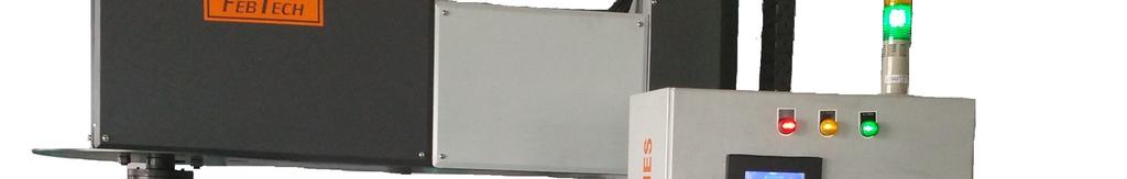
Nitrogen Degassing Unit:
|
|
|
- Elmer O’Neal’
- 5 years ago
- Views:
Transcription


1 Nitrogen Degassing Unit: 1 P a g e
2 INDEX Sr.No Content Page No 1 Degassing Process 3 2 Why Degas 4 3 Degassing Treatment of Alloys 5 4 Process Sketch Working Principle 7 6 Advantages Inbuilt Vacuum (Porosity) Tester P a g e
3 Degassing Process Today, in-line degassing systems are often installed between the holding furnace and casting station to remove impurities. Many degassing systems function automatically, efficiently and without much attention by the operator. Even so, reviewing degasser fundamentals will help to optimize performance and to assess equipment features that are important when choosing a new degassing system. Degassing is increasingly being seen as an essential part of the integrated melt treatment, degassing and filtration Process. In-line degassing performance itself benefits from good upstream processing activities in the furnaces, and in turn benefits other downstream in-line processes such as filtration. These systems are mutually complementary and their combined effect is greater than their individual performance contributions. These in-line treatments and processes should be selected based upon the specific quality specifications. In rotor degassing / fluxing systems, a metered amount of inert gas and/or flux is injected into the molten aluminum through the rotating graphite shaft and rotor. The rotor shears the inert gas into tiny bubbles and disperses them evenly throughout the melt. Unwanted hydrogen gas and non-metallic inclusions are attracted to the inert gas bubbles and rise to the surface. The flux injection allows a steady flow of flux below the metal line which promotes oxide entrapment. The combined effect of gas injection and fluxing helps improve the quality of aluminum alloys and reduces overall operating costs 3 P a g e
4 Why Degas? As its name implies, the primary purpose of the in-line degasser is to remove dissolved hydrogen from the melt prior to and as close as practicable to the casting station. Hydrogen is the only gas that can dissolve significantly in molten aluminum. The major source of hydrogen is the combustion of natural gas or oil in holding furnaces. High ambient humidity is another source of hydrogen, especially during the hot summer months experienced in many localities. The problem is that hydrogen solubility decreases rapidly as the metal freezes during casting, and the hydrogen comes out of solution, causing such casting problems as twisting and flaking in thin section extrusions and blisters on cast product. Target dissolved hydrogen content depends on the final product application, and can range from 0.20 ml / 100g Al for general 6xxx extrusion billet down to 0.10 ml / 100g Al for rolling slab for aerospace applications. Hydrogen is removed from the molten aluminum by bubbling an inert gas through the metal. Argon and nitrogen are typically used, but argon is preferred for the best metal quality because of the tendency of nitrogen to form aluminum nitride inclusions and more dross. By adding a small amount of chlorine to the inert process gas in degassers, non-wetted inclusions and alkali metal impurities can also be removed more efficiently from the metal. Inclusions in molten aluminum can come from smelting operations, furnace re-melting, or intentional additions (e.g. grain refiners). Inclusions can lead to tears and surface defects in rolling sheet, pinholes in foil, and increased die wear during extrusion. Fifty percent (50%) reduction of non-wetted inclusions is a typical target in degassing systems. Additional mechanical filtration downstream of the degasser (e.g. Ceramic Foam Filter, Rigid Media Filter, etc.) may also be required to meet quality goals. Excessive alkali metal (sodium, calcium, lithium) concentrations can cause edge cracking during slab rolling, and bar / rod breaks. Typical maximum alkali metal concentrations should not exceed 5 ppm for each element. 4 P a g e
5 Degassing Treatment of Aluminum Alloy Type of Alloy Batch Capacity Degassing Cycle Time Hydrogen Content (ml/100g) Before After LM Kg 5 Min LM Kg 6 Min LM Kg 10 Min L Kg 7 Min L Kg 15 Min Nitrogen/Argon work to remove Hydrogen 5 P a g e
6 Inclusion removal after pouring salt/granules Bubbles formation in the degassing rotor 6 P a g e
7 Working Principle: Nitrogen degassing units is a metal treatment system for the degassing and cleaning of aluminum alloys in foundries. Nitrogen degassing units use the impeller principle with patented rotor designs which mixes fine inert gas (usually Nitrogen) with the melt. The gas bubbles are distributed widely through the melt whilst maintaining a smooth melt surface. this results in short treatment times, effective degassing and melt cleaning. The degassing equipment is used for transfer ladles and free standing crucible furnaces. This is custom-made and adapted to foundry s requirements and needs. An advanced control system enables the operator to program various parameters. The degassing treatment runs automatically without any operator involvement once the process has been started. During the degassing process vertex formation is important at the time of cover flux/granules feeding because cover flux goes to bottom side via vertex & mix-up in to the molten metal after proper mixing metal impurities/dross came out on the top side suddenly baffle plate goes to down & break the vertex & stabilize the impurities/dross on top side. 7 P a g e
8 Advantages: Nitrogen Saving : We use 3 sol valve for nitrogen flow i.e. SV1,SV2 & SV3, When cycle start SV1 Operate with low nitrogen Lpm, when degassing rod deep in metal that time SV2 Operate with 10 Lpm for 50% of cycle time & at the time of cover flux (granules) feeding SV3 Operate with 15 Lpm. In this process SV2 when operate hi remove all present gases from Melton metal and SV3 operate with cover flux (granules) hi remove all impurities from Melton metal. Auto cover flux (granules) feeder: In our system no need to feed cover flux (granules) manually, we provided auto cover flux (granules) feeder for auto feeding Baffle Plate Auto Up-down Movement: In the time of degassing cycle baffle plate role at last moment, when impurities (slag) come to top side of Melton metal that time baffle plate goes down & break the vertex is create from degassing process & take all the impurities (slag) one side for collecting. Short Treatment Time: In this machine we use plc logic control system, that give benefit of easy operating & ensure degassing cycle time, granules auto feeding & machine safety application so machine complete cycle without any hurdles. Reduced gas porosity and hard inclusions in castings: Due to complete removal of Hydrogen & inclusion, all the entrapped gases & the impurities removed from the Melton metal & this make metal make pure & bubbles not found in the casting in the form of porosity. Maintenance free unit: We manufacturing all the spare parts of Nitrogen degassing unit for long life & use all branded automation spares. So very low chance of machine break-down Safety Parameter: We design machine & working logic considering for safety & easy working as per below. 1) Up-down movement by geared motor 2) Spindle speed variable by AC drive 3) Degassing ladle / furnace top side safety cover 4) Control panel 24 V dc 8 P a g e
9 System is Reliable, Safe and Smart Reliable Ruggedly designed for years of trouble-free foundry service Reliable Low routine maintenance Safe Safety interlocks for user protection Safe Redundant lift chain for safety Smart Single push button for starting and stopping an auto cycle Smart Self diagnostic tools for simple, quick troubleshooting Smart PLC (programmable logic controller) monitors and controls all aspects of operation Drive Unit Fast and easy shaft change-out coupling featuring less gas leakage AC variable speed electric motor drive for reliable and efficient operation Wide spaced driveshaft bearings for best stability and service life External bearing lubrication fittings All in one system: Our system is capable for degassing process from 100 kg to 1 Ton so no need to purchase new machine if your needs change. Inbuilt Vacuum (Porosity) Tester The machine works on the principal of Strobe-Pfeiffer Test, the machine has been developed solely for the purpose of giving a visual indication of the gas content in aluminum prior casting. Molten aluminum sample is kept inside the chamber and the required vacuum is attained in a matter of 7 10 second. 9 P a g e
10 The molten sample is kept under vacuum for about 5 7 minutes, and residual gas inside the sample is indicated on the upper surface of the sample as well as very prominently indicated as blow holes when the sample is cut/machined. The size & the number of blow holes will depend on the gas content of the sample. The sample if cooled under atmospheric pressure will not indicate the gas content as the one which has been cooled/solidified under vacuum and would have wrongly passed quality check prior casting. Technical Description: Vacuum Chamber The main component of this machine, so designed as to withstand high vacuum as well as to attain vacuum merely on closing the lid without any clamping required. The spherical chamber comprises of two hemispheres of SS-304. Each hemisphere is of a single piece. The chamber is tested for vacuum up to 5 x 10⁻⁶ Torre. Vacuum Pump A high vacuum pump, driven by a 0.5hp single phase motor. Suction Filter This filter is solely responsible for making the machine almost maintenancefree. The element is of stainless steel 25 micron mesh. The housing is designed in such a way that dismantling is done merely by opening only one butterfly nut. The whole cleaning process can be achieved by a semi-skilled person in a matter of minutes. The housing is also of stainless steel and can withstand the same vacuum as the chamber and is similarly vacuum-tested. Vacuum Regulator From feedback received from various users, it was found that various alloys require different level of vacuum. This can regulate the vacuum from 500 to -760mmHg (Effective range for vacuum sampling normally is between -630 and -760mmHg). The regulator knob is located on the control panel. 10 P a g e
11 Control Panel Over-load protection for the motor is provided. Various LED indicators are mounted on the panel. The vacuum indication is thru a digital display & vacuum sensing is done by a vacuum (pressure) transmitter. Operation: 1. Switch on the mains supply by putting on the MCB on the front panel. The LED Vacuum indicator will read 0 (+/- 3). 2. Open chamber lid fully, place empty crucible to hold the molten aluminum sample & press vacuum start button. The vacuum pump will start The molten sample should be poured into the crucible immediately & the lid closed. The vacuum in the chamber will increase & will be indicated on the vacuum indicator on the front panel (should read between -720 and -760 mmhg). Whilst pouring the molten sample, care should be taken, not to spill the same on the sealing surface or the O ring of the chamber. In case of a spill, abort the operation & start again after cleaning the spilt aluminum. 3. Wait for the sample to cool/solidify under vacuum. The machine is set for about 5 minute cycle. If any variation in cycle time is required, this maybe carried out by opening the front panel & varying the timer accordingly. 4. After the vacuum cycle is over, the Vent lamp will come on, the chamber will then get vented automatically & the lid can be opened. The sample may then be taken out. 5. The top surface of the sample will appear relatively smooth when the sample does not contain unacceptable level of gas. It will be bubbly & rough if the sample contains unacceptable level of gas. Furthermore the sample may be machined in the center to observe the blowholes. Excessive number of blow-holes indicates higher gas content or porosity 11 P a g e
12 Mfg By Feb Tech Industries L 34 & 35 MIDC Waluj Aurangabad Maharashtra (India) febtech2007@gmail.com Cell: P a g e