Chapter 11: Passives: Discrete, Integrated, and Embedded. Johan Liu
|
|
|
- Harvey Mason
- 5 years ago
- Views:
Transcription
1 Chapter 11: Passives: Discrete, Integrated, and Embedded Johan Liu 1

2 Types of Passive Components 2
3 Embedded passive devices: advantages Reduced system mass, volume and footprint. Individual packages are eliminated and passives can go underground, leaving more room on the surface for ICs. Improved electrical performance. Integrated passives can have lower parasitics, particularly, much lower inductance in capacitors. Due to the elimination of leads and the shorter connections between passive components and other IC chips. Increased design flexibility. The component s resistance, capacitance, or inductance can be sized to any desired value within the technology s range. Improved reliability. Solder joints are eliminated. Reduced unit cost. Integrated passives can be formed simultaneously and with very low 3 incremental cost. Also, they are inherently lead-free.
4 Embedded passive devices: 4 problems Problems regarding materials and processes New materials, processes and test systems are required. Lack of design tools for both component sizing and system layout. Requires vertical integration The same company must manufacture both substrates and passives. Yield issues One bad component can lead to scrapping the entire board. Tolerance issues Integrated passives cannot be presorted prior to inclusion on the board. Lack of standardization The various segments of the integrated passive industry aren t speaking the same language Surface-mount technology is improving moving towards Lack of costing models It is not easy to tell when integrated passives might be more cost effective.

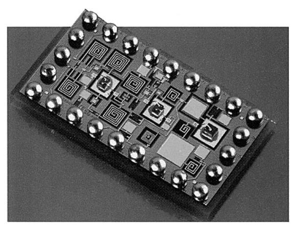
5 Embedded passives Passive components integrated into MCM substrate Embedding means miniaturization 5


6 Embedded passives Inductor 80-20,000Ω insite TM Embedded resistors 6 Embedded resistor
 Spin-coating dielectric material Silicon Wafer dc-sputtering Au (top")
7 Capacitor prototype fabrication Silicon Wafer Silicon Wafer Silicon Wafer dc-sputtering Au (bottom electrode) Spin-coating dielectric material Silicon Wafer dc-sputtering Au (top electrode) 7
8 Pros and cons of embedding passives 8 Benefits Smaller board area, low weight and profile. Less parasitics and more suitable for high frequencies. Lower energy consumption. Higher assembly yield and lower assembly costs. Shorter signal paths and less wiring density required. Challenges More complex design in 3-D. Low temperature fabrication process compatibility. Reduction of manufacturing cost required. Thermomechanical reliability. Board manufacturing complicated and yield too low. Crosstalk in high density packaging.
9 But why bother about passives? Passive components are key functional elements of all electronic systems and substantially influence system cost, size and reliability......hence, providing increased functionality and/or miniaturization options A typical circuit board contains 80% passive components mounted on 50% of the board area. 9

10 Passives in Nokia 6161 cell phone 10 Cell phone board (part of the board) showing the footprints of surface mount passive components marked in white [Integrated Passive Component Technology, Edited by R.K. Ulrich and L.W. Schaper, ISBN , 2003].
11 Resistor technology Resistors Fixed value Variable Carbon composite Metal film Wirewound Rheostatic Potentiometer Passives can be through hole mounted, surface mounted or printed 11
12 Fixed resistors Molded carbon composite Use a mixture of carbon powder with a polymer binder G, 5-20 %,<2 W, Cheapest! Wire wound Formed from windings of fine wires. (CrNi, CuNi on ceramic core) The resistance alloy is winded on an insulator form, and then inserted in a ceramic case k, <0,5 %, Very stable but get hot! Film layer Use carbon or metal film deposited on a substrate (carbon, metal, - oxide thick film on ceramic base) 1-1 G, %, Metal film well is suited for HF 12


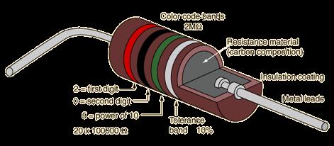
13 Carbon composite resistors Inside a carbon resistor is a 'core' of compressed graphite surrounded by ceramic with copper 'leads' coming out the ends (to allow soldering). The degree of compression, the length of the core and additives (such as clay) determine the resistance of the 'core'. 13


14 Wire wound resistors Wirewound resistors are made by winding thin wire onto a ceramic rod. They can be made extremely accurately for use in multimeters, oscilloscopes and other measuring equipment. 14

15 Film resistors Carbon film A thin film of carbon is deposited onto a small ceramic rod. The resistive coating is spiralled away in an automatic machine until the resistance between the two ends of the rod is as close as possible to the correct value. Metal leads and end caps are added, the resistor is covered with an insulating coating and finally painted with coloured bands to indicate the resistor value. Metal film and metal oxide resistors are made in a similar way, but can be made more accurately to within ±2% or ±1% of their nominal value. 15

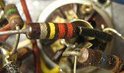
16 Through-hole mounted resistors Cylindrical body with two axial leads. 16


 Terminals (end")
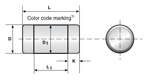
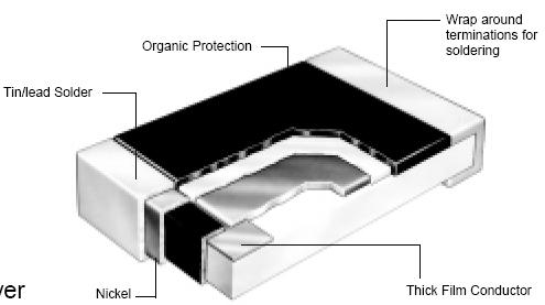
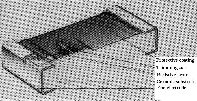
17 Surface mounted resistors Rectangular ceramic body with two solder terminals, often referred to as a chip resistors (MELFs are cylindrical) Size code x x MELF: Metal Electrode Leadless Face Ruthenium oxide thick film, typ. 1-5 % tolerance Thin film technology using Ni-Cr or TaN Internal electrodes: most often silver (Ag) Terminals (end electrodes): Sn-Pb over Ni (barrier) or Ag-Pd, the latter also suitable for adhesive joining) mm x x 1.25


18 18 Resistors Surface mounted

19 Color Digit Multiplier Tolerance Black 0 1 Brown % Red % Orange 3 1,000 Yellow 4 10,000 Green 5 100,000 Blue 6 1,000,000 Violet 7 Grey 8 White 9 Gold 0.1 5% Silver % 19 Color codes The resistance value and tolerance can be determined from the standard resistor color code. A 100R resistor with 5% tolerance may be anywhere between 95 and 105 ohms.
20 Standard values There are a number of different standards, commonly known as: E12, E24, E48 and E96, meaning that there are 12, 24, 48 or 96 individual values per decade (e.g. from 1k to 10k). The most common are the E12 and E24 series The E12 and E24 series follow these sequences: E E24
21 Screened-on resistors In many cases the resistor is not a component added to the circuit, but a thick film creation applied as a paste to the circuit board between two conductive pads. These are screened-on resistors. Normally made to be adjustable by laser/abrasion manipulation of the path, such as the path gets elongated or narrowed in order to increase resistivity until target is achieved. 21
22 Resistance adjustment The resistance adjustment of fired resistors forms an integral part of thick-film technology. This adjustment is done either by: Laser trimming : Evaporation of part of the material from the substrate by a high-power laser-beam. Air abrasive trimming : Stripping off a portion of the resistor material by a narrow jet of abrasive particles. 22


23 Laser trimming Laser trimming is a way of achieving precision adjustment of the attributes of an electronic circuit. A laser removes material from the appropriate component and thus adjusts its value. Laser beam vaporising a cut into the resistor element. Precise and fast process. Low cost. Clean process. Stability depends critically on process. Increased noise. 23 'L' cut into a thick film resistor 'Serpentine' cut 'Shave' cut
24 Abrasive trimming Sandblasted using a small nozzle. Very good long-term stability. Minimum equipment. Slow and dirty compared to Laser trimming. 24
25 25 Capacitors
26 Main types of capacitors 1. Aluminum electrolytic 2. Ceramic 3. Tantalum 4. Film 26


27 Electrolytic capacitors An ELECTROLYTIC CAPACITOR is used where a large amount of capacitance is required. An electrolytic capacitor contains an electrolyte. Two main types: Wet electrolytic capacitor (the electrolyte is a liquid). Dry electrolytic capacitor consists essentially of two metal plates separated by the electrolyte. In most cases the capacitor is housed in a cylindrical Al container which acts as the negative terminal of the capacitor The positive terminal is a lug (or lugs) on the bottom end of the container. 27


28 Electrolytic capacitors Aluminum electrolytic: Consists of two foils interleaved with an absorbent paper, and wound tightly into a cylinder. The positive foil, or anode, is made from pure Al foil on the surface of which Al oxide dielectric has been formed electrolytically. The foil has been etched to increase the effective surface area, and the area of the anode is typically times larger than the plan area of the foil. Polar (care must be taken when mounting) Anode: aluminium foil Dielectric Anodic oxidation of aluminium foil Cathode: liquid electrolyte High C values: 0.1 µf F ± 20 % 28

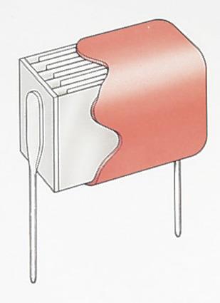
29 Ceramic capacitors Ceramic: Contains a ceramic dielectric. Most dominant in both volumes and % of market share. They are constructed in rolled or stacked form. The ceramic is typically a soft, flexible film before firing. The electrode material is screen printed onto the layers. These capacitors are very rugged, have low to mediate C. 0,5 pf µf Change from palladium to nickel, copper or silver - palladium as metallisation Reduced cost Needs reduced sintering temperature Too high sintering temperature can lead to grain growth and evaporation of fluxes Porosity 29

30 Cracking of ceramic capacitors Common problem! 30
31 Tantalum capacitors Tantalum electrolytic: Similar to Al electrolyte capacitors. Instead of rolled Al foil, the very large surface is obtained by using a very porous pressed pellet of Ta. Ta oxide is the dielectric and the second electrode is wet (electrolyte paste) µf Very thin dielectric -> high capacitance 31


 and the multi-porous Ta assumes the role of the anode.")
32 Tantalum capacitors Solid tantalum Made by forming a rectangular parallelopiped from Ta powder around a Ta wire and sintering into a solid at more than 1,000 C in vacuum. The 0.3-µm powder particles form a solid multiporous material with 1-µm pores. The pores increase the slug's surface area, increasing the device's capacitance. This multi-porous material is submerged in a liquid and a metal oxide layer is created on the surface. This layer becomes an insulating layer /capacitor s dielectric) and the multi-porous Ta assumes the role of the anode. The cathode, which must cover all of the pores on the slug's surface, has traditionally been made from MnO 2 by soaking the slug in liquid manganese nitrate. 32

33 33 Tantalum capacitors
34 Film capacitors Film: Utilize an insulative film of plastic (polyester, polycarbonate, polypropylene, polystyrene) or fired ceramic. Two main types: Rolled foil Two conductive electrodes, either individual metal foils or as a thin metallization film, separated from each other by a plastic film are wound into a cylindrical shape. Stacked layers 10 pf- 100 µf, Low losses, bipolar, for decoupling and filter usage. 34
35 Film capacitors Rolled foil: Al / plastic Metallised ceramic Dielectric 20 mm Noble metal electrodes (Pd or Pt) 35


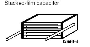
36 Film capacitor Stacked 36
37 Coupling Capacitors pass AC but block DC signals (when charged up to the applied dc voltage), => they are often used to separate the AC and DC components of a signal. This method is known as AC coupling or "capacitive coupling". A large value of capacitance (whose value need not be accurately controlled, but whose reactance is small at the signal frequency) is employed. 37

38 Capacitor packages 38 SMD: ceramic at top left; SMD tantalum at bottom left; Through-hole: tantalum at top right; through-hole electrolytic at bottom right. Major scale divisions are cm.
39 39 Inductors


40 Inductors An inductor is an impedance device comprising a coil, with or without core, for introducing inductance into an electric circuit. 40

, various grades of steel or ferrite materials.")
41 Inductors The magnetic material in the core increases the magnetic field inside the coil by the factor, µ r. An iron core with a relative permeability µ of 10 4 can significantly increase the magnetic field. Inductance materials: The most common winding material is Cu. Core types: Air (lowest inductance), various grades of steel or ferrite materials. May be toroidal (shape like a ring) or can be in the traditional El format. 41