Correlation Study Using Moldflow MuCell for Lightweighting. Tim Lankisch Director of Engineering CAE Services Corporation
|
|
|
- Susan Wells
- 5 years ago
- Views:
Transcription


1 Correlation Study Using Moldflow MuCell for Lightweighting Tim Lankisch Director of Engineering CAE Services Corporation
2 Class summary This class focuses on a correlation study done using Moldflow s Microcellular (or, MuCell ) Injection Molding simulation module. After establishing a reasonable correlation, a strategy for using the analysis module is offered.
3 Why Did I Want to Do This? CAE Services in the Automotive Industry MuCell important for lightweighting CAFE (Corporate Average Fuel Economy) 54.5 mpg by 2025 Getting requests to do MuCell analysis Trexel recommends using a makeshift method using standard module Wanted to understand the differences between using the standard and MuCell modules
4 Key learning objectives At the end of this class, you will: Learn how the MuCell molding process works Learn the MuCell methodology to determine weight savings Learn how to setup a MuCell analysis in AMI Learn how well AMI MuCell analysis correlates with molded samples Understand relationships among common inputs and results Understand the differences between using the standard and MuCell modules
5 The MuCell Process
6 MuCell Molding Fundamentals What is MuCell? Why use MuCell? Who invented it and who owns it now? When / Where was it invented? How is MuCell done? Current developments in MuCell
7 What is MuCell? Microcellular injection molding Mechanical (not chemical) foaming method to impart a microcellular structure to molded parts Millions of cells created on order of microns
8 Why Use MuCell? Weight reduction (commonly up to 15%) Reduced viscosity = reduced pressures to fill Reduced clamp force requirement (foaming = packing) Improved warpage Reduced sink marks Reduced cycle times
9 Advantages Over Chemical Foaming Chemical foaming requires significantly thicker walls = increased weights MuCell can be done at any wall thickness
 in the 1980s Formation of microcellular structures in plastic parts 1995 Trexel, Inc.")
10 Who invented it, when, and where? Foundations based on work done by Dr. Nam Suh (MIT) in the 1980s Formation of microcellular structures in plastic parts 1995 Trexel, Inc. obtained exclusive license Continued development & commercialization up to today
11 The MuCell Process Molding machine is modified or comes pre-fit with gas-injection unit A super-critical fluid (SCF) is injected into the melt stream SCFs include N 2 and CO 2 Typical dosage = 0.2% - 1.0% The Trexel unit injects SCF into screw / barrel area 2/3 of way down barrel Pressurized, single-phase, SCF-polymer solution injected into part cavity Shot size reduced from equivalent solid shot (say 90%) Drop in material pressure initiates immediate cell nucleation
12 Molding Machine Modifications (MMU or OEM) Molding machine is modified or comes pre-fit with gas-injection unit
")
13 Super-Critical Fluid (SCF) Formation
14 Mold Modifications Hot runner molds require valve gates to prevent material drooling Molds where machine nozzle breaks contact need shutoff E.g., Stack Molds Use larger gates due to typically faster injection speeds Exception: Sub gates may not de-gate well with larger size
15 MuCell Molding Strategy
16 MuCell Molding Strategy SCF dosing % determined based on polymer Gradually reduce stroke (reduced shot volume) Gradually increase injection speed at each stroke setting until filled (promotes cell nucleation) Faster filling speeds possible due to reduced viscosity Little to no packing time needed (0.5 seconds) Pack at least as high as back pressure to maintain screw balance
17 MuCell in Moldflow (AMI 2014)
18 Step 1 - Microcellular Injection Molding Module
 No special modeling")
19 Step 2 Part Modeling Midplane or Dual Domain (no 3D) No special modeling considerations

20 Step 3 Mold Modeling Hot Runners need Valve Gates! Pressurized material prevented from seeping into mold prematurely
21 Step 3 Material Modeling MuCell reduces the viscosity of the material up to 30% 12 15% reduction is typical Viscosity reduction model testing PS material (Styron 666D) from an in-mold rheometer Moldflow materials database Correction factors based on these tests You must actively turn on the viscosity modification Different viscosity modification, gas solubility and diffusion coefficients are used for N 2 and CO 2

22 Step 3 Material Modeling Give it Some Gas!


23 Step 3 Material Modeling N 2 Coefficients CO 2 Coefficients
24 η v c 1 Step 3 Material Modeling Gas/Polymer Viscosity Model = ( 1 η r+ φ )v e xp( 2 v c ) 3 Where: η = viscosity of gas/polymer system η r = viscosity of the base resin without gas φ = volume fraction of the nucleated gas bubble c = initial gas concentration v1, v2, & v3 = data-fitted coefficients
25 η r 3 5 * 5 1 η r 1 η v c 2 v c 1 v Step 3 Material Modeling = ( 1 η r+ φ ) e xp( 3 2 ) During 1 st Stage Injection: φ = 0; (i.e., no bubble growth) N 2 CO 2 = ( 1 η = ( 1 η 0 ) e xp( 0 ) e xp( * * % viscosity reduction Foaming Stage 0<φ<1 = reduction in viscosity But flowfront slowdown means η r dominates * η ) = 2 = 5 ) 0.88η r r
26 D Step 3 Material = 1 e d k 1e 2 k T 2 d Gas Diffusion Model d 1, d 2 are data-fitted coefficients κ = T 2 Gas Solubility Model k 1, k 2 are data-fitted coefficients

27 Step 4 Process Modeling Key Assumption Cell Nucleation Nucleation = the birth of a bubble MuCell Nucleation occurs during 1 st stage Nucleation is non-uniform Moldflow No nucleation during 1 st stage Nucleation is uniform
28 Step 4 Process Modeling MuCell Process Bubbles nucleate and grow during 1 st stage Foaming is non-uniform Foaming reduces viscosity Foaming continues during brief packing 0.5 sec. typical Packing helps stabilize the start of screw rotation Foaming continues until cavity is filled
29 Step 4 Process Modeling Moldflow MuCell 1 st stage No nucleation during 1 st stage Viscosity modified N 2 constants Cells/volume setting 1 st stage filling ends at user-specified shot % Moldflow MuCell 2 nd stage Foaming starts at user-specified shot % Foaming replaces packing Exception: Packing told to start before foaming Nucleation starts at user-defined bubble radius mm typical (1 micron) Bubble growth calculated due to: Hydrodynamic Growth Gas Diffusion

30 Step 3 Material Modeling Other Assumptions Foam is divided into spherical microscopic unit cells of equal and constant mass Number of cells = number of nuclei Bubble radius is calculated at each time step
31 Step 4 Process Modeling Faster filling is typical More shear = better nucleation Lower viscosity

32 Step 4 Process Modeling NOT USED UNLESS IT OCCURS BEFORE FOAMING

33 Step 4 Process Modeling Why do we have these? No nucleation model Viscosity modification Starting point for bubble growth

34 Step 5 Analyze
35 Case Example - Correlation

36 The Part Oil Pan 30.0 x 10.0 x x 254 x 122 mm
37 The Part Moldflow Model Two Models: 40,000 elements 8,000 elements

38 The Mold Manifold Design Hot Manifold : Synventive 16E Inlet 16.0 mm Main Bore 16.0 mm Nozzle Bore 16.0 mm Valve Pins 6.0 mm Gate Orifices 5.0 mm

39 The Material Molded Material Polifil T-20 20% talc-filled PP C Moldflow Material Hi-Prene MT42HS 20% talc-filled PP C Quality Standard = Gold
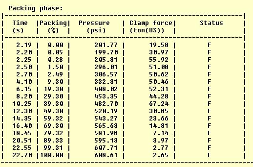
40 The Process Solid Shot Shot Stroke 11.0 Fill Time 3.8 sec. Fill Pressure 8373 psi Part Weight 950g Final MuCell Shot Shot Stroke 9.8 Fill Time 2.0 sec. Fill Pressure 11,500 psi Part Weight 845 g


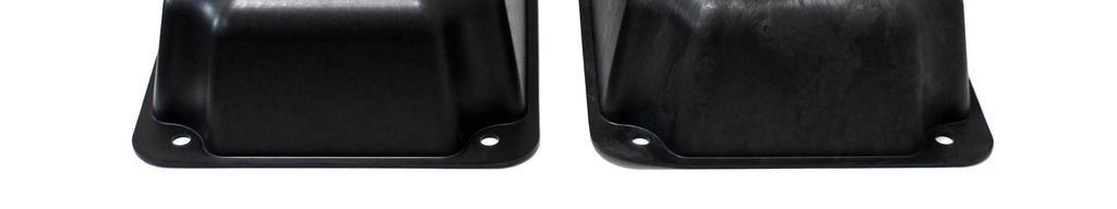
41 Molded Parts Solid Shot MuCell Shot

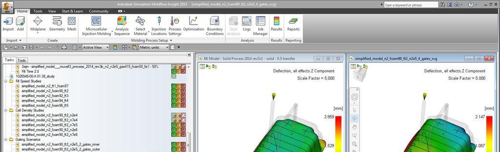
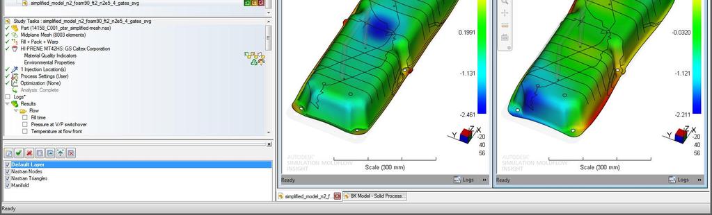
42 The Analysis Setup Solid Shot


43 Solid Shot Part Weight Results Total Part Weight Predicted g Actual g


44 The Analysis Setup MuCell Shot


45 MuCell Shot Part Weight Results Total Part Weight Predicted Huh? Actual g
46 MuCell Shot Part Weight Results Reduce Pack Time Shut Valve Pins Correct SCF % Use Fill Time


47 Autodesk is a registered trademark of Autodesk, Inc., and/or its subsidiaries and/or affiliates in the USA and/or other countries. All other brand names, product names, or trademarks belong to their respective holders. Autodesk reserves the right to alter product and services offerings, and specifications and pricing at any time without notice, and is not responsible for typographical or graphical errors that may appear in this document Autodesk, Inc. All rights reserved.