Supporting Information
|
|
|
- Merry Hawkins
- 5 years ago
- Views:
Transcription

1 Copyright WILEY-VCH Verlag GmbH & Co. KGaA, Weinheim, Germany, Supporting Information for Adv. Mater., DOI: /adma Bioinspired, Spine-Like, Flexible, Rechargeable Lithium-Ion Batteries with High Energy Density Guoyu Qian, Bin Zhu, Xiangbiao Liao, Haowei Zhai, Arvind Srinivasan, Nathan Joseph Fritz, Qian Cheng, Mingqiang Ning, Boyu Qie, Yi Li, Songliu Yuan, Jia Zhu, Xi Chen, and Yuan Yang*
2 Supporting information Bio-inspired, spine-like flexible rechargeable lithium-ion batteries with high energy density Guoyu Qian, Bin Zhu, Xiangbiao Liao, Haowei Zhai, Arvind Srinivasan, Nathan Joseph Fritz, Qian Cheng, Mingqiang Ning, Boyu Qie, Yi Li, Songliu Yuan, Jia Zhu, Xi Chen and Yuan Yang* 1. Calculations of Energy density of the spine-like and prismatic batteries a. Spine-like battery number: 0623 Surface density of active materials (LiCoO2): mg/cm 2 (The amount of anode is excessive) Area of active materials (LiCoO2): 70 mm 9 mm mm 5 mm 9 = cm 2 Mass of active materials (LiCoO2): mg/cm cm 2 = g Specific capacity of the battery: mah/g (refer to Figure S1a) g =123.5 mah Calculation of the volume (refer to Figure S1b): The extra edge is also taken into account. We assume the width of the edge is 1 mm, and the thickness of the edge part is 0.45 mm. Volume = 13.9 mm 5 mm 2.37 mm mm 1 mm 2.37 mm mm 7 mm 0.65 mm 2 + ( ) mm 1 mm 0.45 mm mm 1 mm 0.45 mm 2 = 1933 mm 3 = cm 3 Specific capacity = mah /1.933 cm 3 = 63.9 mah /cm 3 Energy density = 3.78 V (refer to Figure S1a) 63.9 mah /cm 3 = 242 Wh/L. b. Prismatic battery number: 0814 Surface density of active materials (LiCoO2): mg/cm 2 (The amount of anode is excessive) Area of active materials (LiCoO2): 53 mm 95 mm 1 = cm 2 Mass of active materials (LiCoO2): mg/cm cm 2 = g Capacity of the battery: mah/g (refer to Figure S1c) g =89.83 mah Calculation of the volume (refer to Figure S1d): The extra edge is also taken into account. We assume the width of the edge is 1 mm, and the thickness of the edge part is 0.45 mm.

 70.")
3 Volume = mm 14.2 mm 1.42 mm 1 + ( ) mm 1 mm 0.45 mm mm 1 mm 0.45 mm 2 = 1210 mm 3 = 1.21 cm 3 Specific capacity = mah /1.21 cm 3 = mah /cm 3 Energy density = 3.78 V (refer to Figure S1c) mah /cm 3 = 281 Wh/L (e)
4 Figure S1 Galvanostatic charge-discharge curves for the 3rd cycle of the (a) spine-like and (b) prismatic battery. The size of (c) 0623 spine-like and (d) 0814 prismatic battery. Thickness 1 is that of multiple layers of electrodes/separators wrapped together (the vertebrae part). Thickness 2 is the marrow part, which only consists of one layer of cathode, one layer of anode and two layers of separators. Thickness 3 is 0.65 mm. The thickness includes packaging. (e) The CAD scheme of electrode before assembly. The width of every single part is 5 mm and the gap between them is 1 mm. 2. Estimation of specific capacity of other works (Used in the Table 1) a. Folding paper-based lithium-ion batteries (Ref. 22) Reported mass loading (LCO) = 1.29 mg /cm 2 Capacity of the battery = 1.29 mg /cm 2 4 cm 8 cm 128 mah /g = 5.28 mah Volume = 2 cm 2 cm 0.4 cm = 1.6 cm 3 Volumetric specific capacity = 5.28 mah /1.6 cm 3 = 3.3 mah /cm 3 Energy density = 2.3 V (refer to Figure 3 of ref. 22) 3.3 mah /cm 3 = 7.59 Wh /L b. Flexible wire batteries (Ref. 23) Reported linear specific capacity = 1.33 mah /cm Cross-sectional area = 0.25 π 1.8 mm 1.8 mm (refer to Figure S3 of ref. 23) = cm 2 Volumetric specific capacity = 1.33 mah /cm / cm 2 = 52.3 mah /cm 3 Energy density = 1.5 V (refer to Figure 2 of ref. 23) 52.3 mah /cm 3 = 78.4 Wh /L c. Bendable inorganic thin-film battery (Ref. 25) Reported areal energy density = 106 μah /cm 2 Reported energy density = 2.2 Wh /L Volumetric specific capacity = 2.2 Wh /L /3.8 V (refer to Figure 3 of ref. 25) = mah /cm 3 d. Origami lithium-ion batteries (Ref. 29) Reported areal specific capacity = 1.1 mah /cm 2 Thickness of the battery = 380 μm = cm Volumetric specific capacity = 1.1 mah/cm 2 /0.038 cm = 29.0 mah /cm 3 Energy density = 2.4 V (refer to Figure S2 of ref. 29) 29.0 mah /cm 3 = 69.6 Wh /L
5 e. Highly conductive paper for energy-storage devices (Ref. 30) Reported mass specific capacity = 110 mah /g Reported mass loading = 2 mg /cm 2 Capacity of the battery = 110 mah /g 2 mg /cm 2 5 cm 2 = 1.1 mah Volume = 5 cm μm = 0.15 cm 3 Volumetric specific capacity = 1.1 mah /0.15 cm 3 = 7.33 mah /cm 3 Energy density = 2.6 V (refer to Figure 4 of ref. 30) 7.33 mah /cm 3 = 19.1 Wh /L 3. Effective bending stiffness of the spine-like battery The spine-like structure is composed of thick stacks with n layers and thin interconnects with monolayer electrode. Since the Cu and Al current collectors dominate the mechanical properties of electrodes, for simplicity, we assume both the effective modulus and thickness of monolayer electrode are constant. The flexibility of the spine-like structure is determined by its unit cell as shown in Figure 5(a). We evaluate the bending stiffness through calculating the spring constant per unit width of the structural cell as a cantilever, k = F/wδ, where w is the structure width and δ is the maximum deflection when subjected to the point force F. k = k 0 (1 x) x(1 x) x2 (1 x) + n 3 x n3 x 2 (1 x) n3 x(1 x) 2 ] where the dimensionless parameter x defines the length fraction of thin joint in the unit cell, and we set n = 5, consistent with the above experiments. k 0 represents the spring constant of the structures without soft interconnects. 4. Details of finite element simulations The large geometric deformation of three battery structures wrapped on human wrists, including spine-like, stacked and prismatic designs, was investigated by rolling them up the elliptical cylinder (see Figure. S1) using non-linear finite element simulation, which is implemented in the commercial package ABAQUS. The simply supported boundaries were adopted at the two short boundaries of battery structures. The two long boundaries are free for stacked battery, whereas both the displacement (along cylindrical axis) and all rotational freedoms of the two long boundaries are fixed in order to simulate the prismatic structure. The cylinder is fixed in all cases. We use thin-shell elements to simulate the structural solid. In addition, the short end of battery structure is rotated relative to the other end in order to study the torsion deformation.


6 Figure S2 Schematic of battery structure wrapped on the cylinder with elliptical cross-section of a = 32mm, b = 17.9mm, which has the minimum curvature radius of 10 mm. Supplementary Figures S3-S10 Figure S3. The flexed configuration of spine-like battery with a bending diameter of 20 mm when taken the static electrochemical test.
7
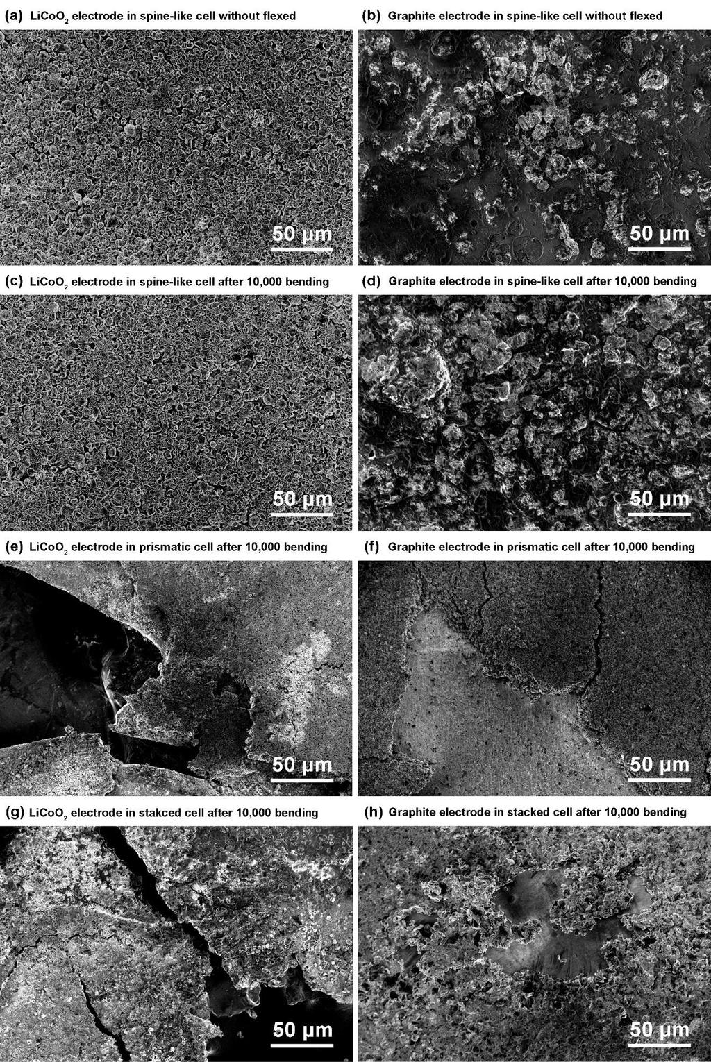
8 Figure S4. (a-d) Scanning electron micrographs (SEM) of cathode and anode of spine-like batteries at the part of bending. (a) unflexed-licoo2, (b) unflexed-graphite, (c) after 10,000 times bending-licoo2 and (d) after 10,000 times bending-graphite. e-f) SEM of cathode material LiCoO2 (e) and anode material graphite (f) of rolled structural batteries after 10,000 times bending. g-h) SEM of cathode material LiCoO2 (g) and anode material graphite (h) of stacked structural batteries after 10,000 times bending. Figure S5. The Nyquist plots of the (electrochemical impedance spectroscopy) EIS measurements taken before and after 10,000 bending of spine-like battery (a) and prismatic battery (b), respectively. EIS measurements were performed at frequencies ranging from 1 MHz to 0.01 Hz at amplitude of 10 mv and were carried out while keeping the batteries in a flat configuration.
 The whole discharge voltage profile.")
9 Figure S6. The discharge curve of spine-like cell at discharge rate of 0.5 C in which the cell was continuously flexed and twisted. a) The whole discharge voltage profile. The different amplified parts of the discharge curve at b) min; c) min; d) min.
 spine-like battery, (b)")
10 Figure S7. The photographs of (a) spine-like battery, (b) prismatic battery and (c) stacked battery.
 Optical images at the cut of bending of cathode current collector Aluminum for spine like structure (1) unflexed, (2) over 5,000 times")

11 Figure S8. Tensile stress/strain curves for the (a) pure aluminum foil and (b) pure copper foil, respectively. Figure S9. a) Optical images at the cut of bending of cathode current collector Aluminum for spine like structure (1) unflexed, (2) over 5,000 times bending, (3) over 10,000 times bending b) Photographs at the cut of bending of rolled structure (left) and stacked structure (right). Figure S10. Finite element results of the maximum principle strain of the spine-like subjected to bend on the cylinder with elliptical cross-section (a=3.2 cm, b=1.8 cm).

12 Figure S11. Tensile stress/strain curves for the spine-like batteries. The inset shows the optical images of the failure of aluminum and copper current collectors. The first and second stress drops are associated with the failure of aluminum and copper current collectors, respectively, which is confirmed by optical images in the inset. Figure S12. The voltage profile of the stacked cell during flexed condition. The voltage experiences tremendous fluctuation. The battery dimensions are the same for spine-like, prismatic and stacked cells.