A CORROSION MONITORING PROGRAMME FOR RESEARCH REACTOR SPENT FUEL BASINS. L.V. Ramanathan, R. E. Haddad and P. Adelfang
|
|
|
- Egbert Watkins
- 5 years ago
- Views:
Transcription
1 A CORROSION MONITORING PROGRAMME FOR RESEARCH REACTOR SPENT FUEL BASINS L.V. Ramanathan, R. E. Haddad and P. Adelfang IPEN, Brazil; CNEA, Argentina; IAEA, Austria. International Conference on Research Reactors: Safe Management and Effective Utilization 5-9 November 2007 Sydney, Australia
2 Outline Corrosion monitoring programmes (CMP) WHY?? The stages of a CMP Guidelines for the different stages of a CMP Examples from IAEA supported projects Concluding remarks
3 Most RR fuels are Al-clad Stored in pools for extended periods (some up to 50 years)
4 Spent fuel storage facilities Type of storage At reactor Away from reactor Pool Dry well Vault Other 18 6


 on")
5 Severe pitting (left) and crevice corrosion (right) on spent fuel surfaces.


6 In-reactor spent fuel storage

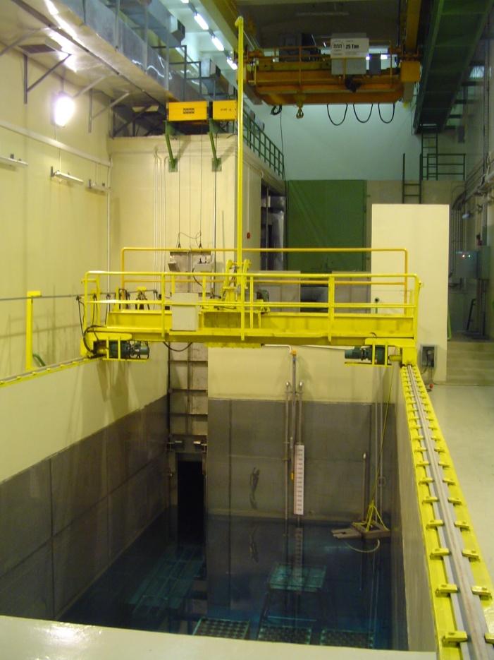
7 Away-from-reactor spent fuel storage


8 Away-from-reactor spent fuel storage


9 Corroded components in spent fuel storage basins
10 Corrosion and especially pitting corrosion, is the main form of degradation of Al alloy clad RR fuel, and could lead to breach of cladding. Besides the hazard of exposure, this often involves contamination of the storage facilities and very expensive clean up procedures. The best option is to avoid this from happening.
11 Good quality water is essential to prevent corrosion. However, certain water parameters, well below levels of concern, have a synergistic effect on pitting corrosion of Al alloys. Hence, maintenance of water parameters within specified limits is not reason enough for complacency about corrosion of fuel cladding.
12 A corrosion monitoring programme (CMP) at a spent fuel wet-storage facility helps evaluate the effect of the prevailing water parameters on the corrosion of spent fuel cladding and/or of other structural materials. It provides an insight into the extent of corrosion of the metallic materials.
13 A CMP usually involves the exposure of test coupons to the basin water for a predetermined period followed by its evaluation to detect for corrosion. The CMP also involves the determination of water parameters at periodic intervals. Other techniques such as electrochemical noise have also been used to monitor corrosion, but to a lesser extent.
14 A CMP keeps the Basin Manager informed of any transients in water parameters, (which often go unperceived in the absence of a CMP) and its effects, if any, on the corrosion of test coupons, and consequently on that of the fuel cladding and other structural materials
15 The main stages of a CMP at a spent RR fuel storage facility are: (a) The planning stage (b) The execution stage (c) The evaluation stage
16 The planning stage List the metallic materials exposed to the spent fuel basin water along with their composition, microstructure, heat treatment condition and surface condition. This helps select the materials for the program.
17 Specify: (a)type and dimensions of the corrosion test rack, test coupons and insulating separator; (b) duration of the program; (c) frequency of corrosion monitoring; (d) test coupon assembly sequence in the rack; (e) number of racks, coupons and separators; (f) location within the spent fuel basin to place the coupons; (g) water parameters to be monitored and its frequency. (h) Complementary laboratory studies (i) determination of the amount and type of solids that settle on surfaces within the basin.
18 WARNING A successful CMP can be compromised by insufficient attention to: availability of sufficient materials in the desired states. accessories that may be required during the execution stage. availability of laboratory facilities for water analysis, sediment analysis, test coupon evaluation etc.
19 Material selection Select Al alloys representative of the fuel cladding and any other thin walled aluminium alloy components. Select other materials that form bimetallic junctions with the fuel. Essential to know metallurgical state of the alloys and their surface condition Crevice corrosion is another form of localized corrosion and crevices form between two Al alloys. Select Al alloy used for storage racks.

20 The corrosion test rack with coupons
21 Test racks and coupons A variety of test racks with test coupons of varying shapes and sizes have been used in CMPs. The models used in CRP-II and the RLA are recommended as these racks evolved from other designs. The insulating separator should be non-porous and resistant to radiation - dense alpha-alumina.
22 The coupons usually arranged horizontally The coupons - 3 mm thick and 10 cm in diameter stacked in an stainless steel test rack with a stem and a nut with a hook to suspend the assembled rack in the spent fuel basin. Test rack should contain coupons to evaluate crevice and bimetallic corrosion.
23 Test duration and monitoring frequency The number of test racks must be consistent with expected life of the facility, and duration of interim storage of spent fuel. An ideal CMP of a spent fuel basin should envisage surveillance throughout the desired service life of the spent fuel basin. The frequency of corrosion monitoring is the number of times test racks are withdrawn from the storage basin during a CMP.
24 In CMPs at basins with very good quality water, yearly withdrawals of test racks are sufficient. At basins with poor quality water or with significant amounts of settled solids, test rack withdrawals should be at three - or six-monthly., Test racks once withdrawn should not be returned to the basin.
25 Water parameters At in-reactor facilities, temperature, ph, conductivity, chloride, sulphate, iron, and a few heavy metal ion content are monitored and recorded at regular intervals. In away-from-reactor spent fuel storage sites, water analysis, if carried out, is often very infrequent. It is recommended that at the CMP site, water of less than desired quality be analyzed twice a month. If no marked variation in ion composition is noted after 6 months, monthly measurements are suggested.
 hinder regular fuel handling; (2) be knocked about during regular reactor or basin operations; (3) be exposed to")
26 Test rack location Close to spent fuels. The test rack should not: (1) hinder regular fuel handling; (2) be knocked about during regular reactor or basin operations; (3) be exposed to excessive amounts of settled solids, unless it reproduces conditions similar to that of stored fuels.


27 Withdrawn test racks


28 Evaluate settled solids The settled solids, depending on their composition, affect the corrosion of Al alloy coupons. Hence, determine the amount and composition of settled solids.


29 Settled solids collectors.
30 Rates of settling of solids and their composition or constituents. Test site Rate of settling (μg/cm 2 /month) Composition or constituent of settled solid RECH-1, Chile Al; SiO 2 (quartz);sio 2 (cristobalite) (Ca,Na)(Si,Al) 4 O 8 (anortite) RECH-2, Chile. 1.5 SiO 2 (quartz) CDTN, Brazil Amorphous CaCO 3 (calcite); Fe 3 O 4 (magnetite), SiO 2 (quartz); CaMg(CO 3 ) 2 (dolomite)α-al 2 O 3.3H 2 O (gibbsite), Fe 2 O 3 (hematite) Mg 3 Si 4 O 10.(OH) 2 (talc) ININ, México Iron oxides (hematite, magnetite), aluminosilicates, sodium and calcium carbonates România. SF pool, Thailand. Reactor pool, Thailand. Cooling pool, Kazakhstan. Water storage, Kazakhstan. RA3 Decay Pool, Argentina Fe, Zn and Cd 195 Fe, Al, SiO 2, Cu, Ba; Light particles of plant tissue, bio-mass floating in water with some fine dust. 141 Fine light brown dust. Main component is iron Deionizing column resin Deionizing column resin 19.5 Silicon oxide and combined oxides of Si, Al and Fe IPEN, Brazil Al 2 O 3, SiO 2,!4.93 Fe 2 O 3, 2.35 CaO, 1.6 Cr 2 O 3, 0.76 TiO 2, 0.6 NiO (wt%)
31 The execution stage Involves all actions related to: preparing the test coupons and racks, conducting the corrosion program and evaluation of the coupons.
32 Test protocol IAEA-TRS-418 New IAEA Tecdoc in preparation
33 Suspend and identify the racks. Record location and dates of immersion. Measure radiation levels near the rack at periodic intervals. Monitoring the main water parameters at daily or weekly intervals.
34 +15.7 SPENT FUEL RACKS 900 Register position of racks and spent fuel pool (MARIA reactor in Poland)
35 Schematic diagram indicating the position of test racks in the spent fuel storage pool at Vinca, Serbia.
36 Determine impurities in the basin water at regular intervals. Register water flow characteristics near the rack, rate / frequency of renewal of water in the basin etc. Record activities carried out by reactor or spent fuel basin personnel that could affect test results. Prepare and immerse a settled solids collector. Withdraw test rack(s).

37 A test rack being withdrawn.
38 Temperature /1/ /2/ /3/ /4/ /5/ /6/ /7/ /8/ /9/ /10/ /11/ /12/2004 oc Entry - Maxim um Exit - m axim um Limit Conductivity ,50 2,00 1,50 1,00 0,50 0,00 6/1/2004 6/2/2004 6/3/2004 6/4/2004 6/5/2004 6/6/2004 6/7/2004 6/8/2004 6/9/2004 6/10/2004 6/11/2004 6/12/2004 usv Pool Make-up Recirculating Limit ph ,00 6,50 6,00 ph 5,50 5,00 6/1/2004 6/2/2004 6/3/2004 6/4/2004 6/5/2004 6/6/2004 6/7/2004 6/8/2004 6/9/2004 6/10/2004 6/11/2004 6/12/2004 Pool Make-up Limit Temperature, conductivity and ph profiles during 2004 in the spent fuel basin of the IEA- R1 research reactor in São Paulo, Brazil. Change in Fe, Cu and Cl contents in RECH-1 reactor pool in Chile.
39 (µg/ml) (ppm, ph or µs/cm) Chlorides Sulfates ph Conduct. TSS RA6 REACTOR POOL -2 01/05/98 17/11/98 05/06/99 22/12/99 09/07/00 Date (DD/MM/YY) (ppm, ph or µs/cm) (µg/ml) RA6 DECAY POOL Chlorides Sulfates ph Conduct. TSS 01/05/98 17/11/98 05/06/99 22/12/99 09/07/00 Date (DD/MM/YY) Variation of basin water parameters.


40 A test rack with coupons, before and after exposure for a year to a spent fuel basin in Serbia.
41 The evaluation stage Evaluation of the coupons Measure ph of water on the external surface of coupons. Photograph the rack prior to disassembly. Disassemble the rack and remove the coupons. Photograph the coupons. Record specific surface features for each coupon.

 The exposed and contact surfaces")
 Corrosion feature on a AA 6061")
 Corrosion of AA 6061 coupon at")
42 a b (a) White jellylike sludge on exposed surface of a AA 6061 coupon exposed for six years. (b) The exposed and contact surfaces of a crevice couple. (c) Corrosion feature on a AA 6061 coupon exposed for a year. (d) Corrosion of AA 6061 coupon at exposed contact region with a SS coupon. c d


43 Pits in Al 6061 alloy after 2 years of immersion in the RECH-1 reactor pool.
44 Counts Equivalent diameter µm A histogram of number of pits versus pit diameter on a coupon surface.
45 Report CMP results Details on what and how to report can be found in TRS-418 and in the new Tecdoc.
46 Concluding remarks A CMP enables: Correlation of coupon corrosion and water parameters. Prediction of surface state of spent fuel cladding and/or other structural components. To take appropriate actions to reduce corrosion rates.
47 Actions could be: Alterations in one or more water parameters; Changes in housekeeping practices to reduce the extent of settled solids; Adoption of procedures to verify fuel cladding integrity at more frequent intervals.
48 Thank you