REPORT OF PORTION OF PECOS EXPERIMENTAL ROADS PROJECT BUILT BY SCOTT ENVIRONMENTAL SERVICES, INC.
|
|
|
- Tabitha Boone
- 5 years ago
- Views:
Transcription
1 REPORT OF PORTION OF PECOS EXPERIMENTAL ROADS PROJECT BUILT BY SCOTT ENVIRONMENTAL SERVICES, INC. This roadway portion was built by Scott Environmental Services, Inc. (SESI) using its Firmus process from water-base mud and cuttings taken from a reserve pit in a field in onshore coastal south Texas. An analysis of this untreated starting material is attached as Appendix A. In the reserve pit from which the starting material was taken, it was mixed, using a large excavator bucket, with a plasticity reducing agent (PRA). The amount of PRA used had been previously determined by laboratory test to be (i) sufficient to make the mixture, unlike the starting material, easily transportable by truck without loss from sloshing; and (ii) not sufficient to cause the mixture to harden into a monolithic structure. An analysis of the resulting plasticity reduced material (PRM) is attached as Appendix B. The following table shows a comparison of the two materials. TABLE 1: COMPARISON OF UNTREATED AND PLASTICITY REDUCED MATERIAL TESTED CHARACTERISTIC ANALYTICAL VALUE FOR: Untreated Material Plasticity Reduced Material Arsenic, mg/kg, dry basis Barium, mg/kg, dry basis Cadmium, mg/kg, dry basis Chromium, mg/kg, dry basis Lead, mg/kg, dry basis Mercury, mg/kg, dry basis Selenium, mg/kg, dry basis Not detected Silver, mg/kg, dry basis Total C 6-36 Petroleum Hydrocarbons, mg/kg, dry basis Water Extractable Chloride, mg/kg, dry basis Soluble Sulfate It is clear from Table 1 that every analyte tested, except for selenium and soluble sulfate, was substantially reduced in concentration on a dry basis, some by more and some by less than would be calculated based on an assumption that the entire solids content of the raw waste was incorporated into the larger solids content of the treated waste. At the reuse site outside of Pecos, Texas, the following equipment was utilized during road construction, including preparation of the subgrade and construction of the final road: 3-trough cement delivery truck: 25 tons capacity with a rear-end spreader bar Wheel Loader: Case 621D Road Grader with rippers: CAT-140H Reclaimer: CAT-RM 250C Water truck: 2,000 gallons capacity with rear-end spray nozzles Pad-foot compactor: Dynapac CA 150PD (15 tons) Smooth drum roller: Ingersoll Rand SD-70/77 (8 tons). 1
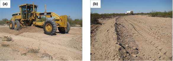
- smooth drum roller. A test section of in situ soil approximately 170 feet long x 14 feet wide (Figure 2) was selected as the test site.")
, and the lift of material was")
2 FIGURE 1 These items of equipment used are pictured in Figure 1, Construction Equipment for Field Test Section: (a)-cement truck; (b)-wheel loader; (c)-grader; (d)-reclaimer; (e)-water truck; (f)-pad foot compactor; (g)- smooth drum roller. A test section of in situ soil approximately 170 feet long x 14 feet wide (Figure 2) was selected as the test site. Work began by watering, scarifying, and compacting the in situ soil (Figure 3), using the water truck, grader, compactor, and roller, to form the road subgrade. Then a single lift of PRM and some water was placed on top of the prepared subgrade in sufficient quantity to have 10 inches of thickness after compaction (Figure 4), and the lift of material was smoothed, shaped, and compacted using the water truck, loader, grader, compactor and roller (Figure 5). Next, a pre-determined amount of Portland cement was spread over the prepared PRM by the cement truck (Figure 6), and then the cement and the PRM were mixed with the reclaimer and grader to a depth of 12 inches, then compacted. (Figure 7). FIGURE 2 2


3 FIGURE 3 FIGURE 4 a and b FIGURE 5 a and b 3

.")
, with additional water")
4 FIGURE 6 a and b FIGURE 7 a and b Water was then sprayed from the water truck over the mixture in an amount to achieve optimum moisture content, as determined by previous laboratory testing, and the wet mixture was again mixed using the reclaimer (Figure 8). After that, all of the emplaced materials were compacted, then bladed and shaped to get a uniform mixture again (Figure 9), with additional water added as needed. FIGURE 8 a and b 4


5 FIGURE 9 Finally, a 2 inch thick layer (after compaction) of aggregate to serve as a friction layer for safer vehicular travel, was placed on top of mixed and compacted material with a belly-dump truck and distributed, but not mixed into the underlying material, with the grader (Figure 10), then watered, graded, and rolled to produce the final road surface shown in Figure 11. FIGURE 10 a and b FIGURE 11 5
6 Construction, as described above, was successfully accomplished in one day, although strength gain in the material continued for several days. The PRM was sampled at several instances during the placement, and a composite sample was formed from these samples and sent for evaluation to a geotechnical testing laboratory, where it was mixed with the percentage of cement used and with an amount of water determined to yield a maximum density mold, then aged for seven days while being maintained moist. After completion of aging, the compressive strength and dielectric properties were obtained by standard tests. Results for unconfined compressive strength compacted at optimum moisture are shown in Table 2. TABLE 2: COMPARISON OF UNCONFINED COMPRESSIVE STRENGTH OF PLASTICITY REDUCED MATERIAL AND CEMENT TREATED MATERIAL DAY Plasticity Reduced Material UCS (psi) Cement Treated Material UCS (psi) Test Details Method: Tex-120-E Mold Size: 6.0 inches diameter, 8.0 inches nominal height Molding Method: 10 pound hammer, 18 inch drop, 50 blows per layer, in damp room Strain Rate: inch per minute The dielectric value after drying stayed within a range of during 10 days in a damp room. This is considered a fully satisfactory performance. As recognized by regulatory authorities, the potential for contamination from a monolithic structure is preferably measured on a leachate from a fractured and graded sample rather than by the methods used for small particle aggregates. Accordingly, the broken pieces from geophysical testing were appropriately graded and submitted for analytical testing of leachates. Detailed results are shown in Appendix C, and a summary and comparison is shown in Table 3. TABLE 3: COMPARISON OF UNTREATED MATERIAL AND FINALLY TREATED MATERIAL TESTED CHARACTERISTIC ANALYTICAL VALUE FOR: Untreated Material Finally Treated Material ph value, standard units Not measured 11.9 Note: All of the following measurements are in milligrams per kilogram on a dry basis for the untreated material and in milligrams per liter of leachate for finally material. Arsenic X 10-4 Barium X 10-2 Cadmium X 10-5 Chromium X 10-2 Lead X 10-5 Mercury X 10-4 Selenium Not detected 2.3 X 10⁻⁴ Silver X 10-5 Total C 6-36 Petroleum Hydrocarbons Chloride* *Water soluble only for Untreated Material 6
7 It is clear from Table 3 that pollution potential from heavy metals and petroleum hydrocarbons has been reduced by orders of magnitude by the final treatment. It is also clear from Table 2 that the geotechnical properties of the final material are excellent for construction base for use on lease roads, drilling pads, tank battery locations, and compressor stations. Therefore, this report indicates that waterbased drilling waste that has been treated using SESI s Firmus process is excellent construction material with minimal environmental impact from leachate. 7