of Titanium The Performance of Titanium at the Speed of Aluminum
|
|
|
- Bennett Lindsey
- 5 years ago
- Views:
Transcription


1 of Titanium The Performance of Titanium at the Speed of Aluminum Cory Tallman, Lockheed Martin ADP Robert Schaffarzyk, Ferra Engineering Milan Brandt, RMIT University Nazmul Alam, CSIRO
 RMIT University Milan Brandt Ferra Engineering Mark Scherrer")
2 TAM is an Industry Team Lockheed Martin Cory Tallman Australia NACC John Wilshire CSIRO Nazmul Alam (PI) RMIT University Milan Brandt Ferra Engineering Mark Scherrer 2
 Cost ($/lb) As a Function of Buy Weight Part (forging) Cost ($/lb) As a Function of Buy Weight $70 $70 $60 $60 $50 $50 $40 $/lb $30 Per Step Cumulative $40")
3 Motivation The Buy to Fly ratio of Titanium is poor, typically 11:1 The Buy to Fly ratio of Aluminum is worse Aluminum machines an order of magnitude faster TAM intends to bring the cost of machining titanium closer to aluminum Part (plate) Cost ($/lb) As a Function of Buy Weight Part (forging) Cost ($/lb) As a Function of Buy Weight $70 $70 $60 $60 $50 $50 $40 $/lb $30 Per Step Cumulative $40 $/lb $30 Per Step Cumulative $20 $20 $10 $10 $- Sponge Plate Machining $- Sponge Forging Machining Machining of Titanium 40% of the cost of part made from plate 60% of the cost of a part made from a forging 3
4 Titanium 101 Ti-6Al-4V is generally classified as difficult to machine because of its thermo-mechanical properties The primary challenge is overcoming short tool life Prevents high cutting speeds Cutting speeds are an order of magnitude slower than aluminum Typical Buy to Fly of Titanium is poor Approximately 90% of material purchased is removed during machining Machining of Titanium can be 40 to 50% of the cost of a titanium part for an air vehicle Goal to reduce cost by improving tool life and maximize Material Removal Rate (MRR) 4
5 Poor Machinability Titanium has low thermal conductivity Impedes heat-transfer out of the cutting zone Creates high cutting zone temperatures Titanium shows high chemical affinity towards the Cobalt binders that are found in most cutting tool materials The interface between Titanium chips and cutting tools is usually quite small, which results in high cutting-zone stresses There is a strong tendency for Titanium chips to pressure-weld to cutting tools. 5
6 Why Lasers? Laser High Travel Speed High Removal Rate Increased Tool Life Machining Cost Reduction Reduces the Roughing Time by 80% Reduces the Cutting Force by 40% Extends the Tool Life 3X* * Tool optimization is under way 6


7 Why it Works Ti 6Al 4V Strength Vs. Temperature Cutting Force With and W/Out Laser Strength 35% Cutting Froce 40% Temperature Conventional LMCut The strength of all metals decreases with temperature Reduces the force required to remove material Reduction in force allows Greater tool life Faster speeds Smaller investment 7
8 Milled Sample with Laser Beam Laser beam Cut depth HAZ Microstructure examined 8


9 Cross Section of Laser Heated Area m/min 5 mm above focal plane Low magnification High magnification 9
10 Hardness Vs Depth Hardness, HV Surface Depth, mm 10


11 Cross Section of Milled Sample No Laser Depth of cut: 1.5 mm Feed speed: 1 m/min Spindle: 3571 rpm Tool diameter: 25 mm Tool engage: 70% Low magnification High magnification 11


12 Cross Section of Milled Sample with Laser Depth of cut: 1.5 mm Feed speed: 1 m/min Spindle: 3571 rpm Tool diameter: 25 mm Tool engage: 70% Low magnification Laser: 1.5 kw High magnification 12


13 Tool Wear Conventional TAM Volume Removed = 3.6 cm 3 Cutting Speed = 200 m/min Volume Removed = 8.4 cm 3 Cutting Speed = 200 m/min Optimizing tools were not an objective of the pilot program Tools chosen for the pilot were COTS Trend is favorable for harder tools, similar to what is on for Al 13
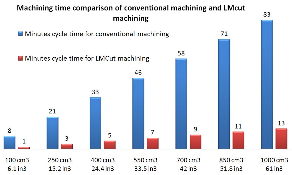
14 Quantifiable Benefits #1 The target is to reduce the cycle time in roughing machining operations. TAM achieved 6 x increase in MRR : 5 x increase in cutting & spindle speed 6 times increase in machining feed rate 80% cycle time reduction for roughing operations 2.5 x tool life increase compared to standard titanium machining using cutting inserts of the same type The more raw material that needs to be removed - The greater the time savings 14
 Volume of finish component cm 3 / (in 3 ) 541 (33) Material to remove cm 3 / (in 3 ) 9,866 (602) Roughing cycle time Min 822 130 15")
15 Quantifiable Benefits #2 85% Reduction in Cycle Time Example Component Unit Conventional TAM Volume of raw material cm 3 / (in 3 ) 10,407 (635) Volume of finish component cm 3 / (in 3 ) 541 (33) Material to remove cm 3 / (in 3 ) 9,866 (602) Roughing cycle time Min

16 Quantifiable Benefits In General 16


17 Schematic Illustration of CNC Cell 1. Laser head carrier 2. Ti bar to be milled 3. Cutting tool 4. Laser head 17
18 Laser Concept 18
19 Progress Has Been Fast By 2011 TAM was shown to be capable of increasing MRR five times for titanium plate materials The laser was building too much heat in the workpiece for thicker sections We had a solution for equipment which utilized a rotating table (i.e. the laser was in a fixed position relative to the spindle) In 2012 we began to scale the solution to include a dynamic position of the laser relative to the spindle A solution was configured for a larger 5 axis system without the necessity of a rotating table A higher power diode laser was acquired which enabled closed loop control for maintaining the temperature in the workpiece In August, the laser system was shipped to Ferra Engineering for factory trials By 2013 we will be in a position to license the IP to an equipment manufacturer 19
20 Principal Advantages By heating the material, the force required is less Reduces wear on the tool Utilize smaller machine (i.e. for aluminum) Can be adapted to existing machines No re-qualification required No liquid coolant required 20
21 Acknowledgements Ram Balar Lockheed Martin ADP, F-35 I&D John Barnes CSIRO Mark Scherrer Ferra Engineering Milan Brandt-RMIT University John Wilshire Australia JSF Industry Team 21
22