VG-Cut. Complete Range of Turning Solutions INCH METRIC. Innovative Grooving & Turning Solutions
|
|
|
- Sandra Hunter
- 5 years ago
- Views:
Transcription


1 VG-Cut Complete Range of Turning Solutions INCH METRIC Innovative Grooving & Turning Solutions

.")
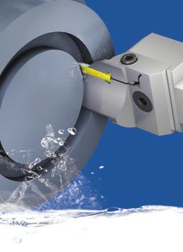
2 VG-Cut Complete Range of Turning Solutions Deep Grooving, Threading, Parting Off, oring and Face Grooving Technical Data _ Page 3 VG-Cut Inserts & _ Page 13 VG-Cut Toolholders & Page 19 The new family of VG-Cut tools by GROOVEX, provides a wider range of applications and options within the same insert pocket of Deep Grooving, Parting Off, Turning, Profiling, oring, Face Grooving and Threading. The VG-Cut inserts also offer a variety of chip formers and carbide grades, making the VG-Cut program a distinctly versatile system. VG-Cut tools cover a wide range of Threading Standards for machining between shoulders and close to the spindle for up to shoulder depth of.394" (10.0 mm). The VG-Cut, with its unique multifunctional geometry, minimizes inventory for the end-user in an extensive selection of applications. Modular Face Grooving Monoblock Modular NEW lades Internal Face Grooving & Turning Parting Off Deep Grooving Turning Profiling Threading Grooving & Undercut between & Turning Shoulders 2

 160-280 Malleable Cast Iron 29 Pearlitic (long chips) 230 140-220 140-260 30 Low Tensile Strength")
3 Insert, Tool and Cutting Data Selection Guide A Identify the Application Identify the Designated Work Piece Material P Alloy Steel M Stainless Steel K Cast Iron N Non- Ferrous S Heat Resistance H Hardened Marerial C D Designated Chip Former Geometry for Selected Applications Designated Carbide Grade for Desired Application page 4 VKG VPG VMG page 5 E F Selecting Insert and Tool as Required by Operation Cutting Data According to Selected Items M Stainless Non Hardened Stainless Steel Steel Cast Ferritic 16 Hardened Austenitic Stainless Steel Cast Austenitic 18 Hardened Ferritic (short chips) Malleable Cast Iron 29 Pearlitic (long chips) Low Tensile Strength Grey Cast Iron K pages pages
4 Designated Chip Former Geometry for Parting Off and Grooving Application Material Group Standard Conditions Extreme Conditions Parting Off P Alloy Steel K Cast Iron H Hardened Material GT Recommended choice for machining alloy and stainless steel. Positive rake chip former leads to low cutting forces during cutting. A multifunctional chip former for parting, grooving and turning. GP Recommended choice for machining cast iron, for interrupted cuts and for unstable applications where accuracy and overall machining stability are not clear. Reinforced cutting edge for parting off and grooving. Grooving M Stainless Steel N Non- Ferrous S Heat Resistance P Mild Steel GM/GF Recommended choice for stainless steel. Positive sharp cutting edge decreases buildup on edge for parting off and grooving in low feeds. GT Recommended choice for machining alloy and stainless steel. Positive rake chip former leads to low cutting forces during cutting, with multifunctional chip former for parting, grooving and turning. Designated Chip Former Geometry for Turning, Profiling and Threading Application Standard Conditions Turning GT Recommended choice for machining alloy and stainless steel. Positive rake chip former leads to low cutting forces during cutting, with multifunctional chip former for parting off, grooving and turning. Profiling GR Recommended choice for grooving, undercut and profiling. Round shape geometric for profiling, and positive rake chip former with multifunctional chip control. Threading RS/LS Varied range of threading standards for machining between shoulders and close to the spindle. 4
5 Designated Carbide Grade for Desired Application Toughness vs. Hardness Toughness VMG M35 VMG - Very tough substrate, secured edge from chipping. PVD coated M35 for low cutting speeds. Recommended for Parting Off on stainless steel and interrupted cuts. VPG P20 VPG - Sub-micron substrate for a wide range of applications. Excellent anti-fracture resistance. PVD coated P20 for medium to high cutting speeds. Recommended for alloy and stainless steel in grooving and turning. VKG K25 VKG - Tough substrate. CVD coated K25. Excellent wear resistance in high cutting speeds. Recommended for cast iron and grooving alloy steels under stable conditions. Hardness Recommended Carbide Grade for Designated Application Application Improved Chipping Resistance Improved Wear Resistance Application Improved Chipping Resistance Improved Wear Resistance VMG M35 VPG P20 VPG P20 VKG K25 Parting Off Turning VPG P20 VKG K25 VPG P20 VKG K25 Grooving Profiling VMG M35 VPG P20 VPG P20 VKG K25 Undercut Face Turning 5
6 Technical Data Recommended Cutting Speeds Vc [ft/min] Material Group Vargus No. Material Hardness rinell H VMG PVD M35 Vc [ft/min] VPG PVD P20 VKG CVD K25 Vc [ft/min] for Parting Off PSteel M Stainless Steel K Cast Iron N(K) Non-Ferrous Metals S(M) Heat Resistant Material H(K) Hardened Material 1 Low Carbon (C= %) Unalloyed Steel Medium Carbon (C= %) High Carbon (C= %) Non Hardened Low Alloy Steel (alloying elements 5%) Hardened Hardened High Alloy Steel Annealed (alloying elements>5%) Hardened Cast Steel Low Alloy (alloying elements <5%) High Alloy (alloying elements >5%) Stainless Steel Non Hardened Ferritic Hardened Stainless Steel Austenitic Austenitic Super Austenitic Stainless Steel Non Hardened Cast Ferritic Hardened Stainless Steel Austenitic Cast Austenitic Hardened Malleable Ferritic (short chips) Cast Iron Pearlitic (long chips) Grey Cast Iron Low Tensile Strength High Tensile Strength Nodular Sg Iron Ferritic Pearlitic Aluminium Alloys Non Aging Wrought Aged Aluminium Alloys Cast Cast & Aged Aluminium Alloys Cast Si 13-22% Copper and rass Copper Alloys ronze And Non Leaded Copper Annealed (iron based) High Temperature Aged (iron based) Alloys Annealed (nickel or cobalt based) Aged (nickel or cobalt based) Titanium Alloys Pure 99.5 Ti 400Rm α+β Alloys 1050Rm HRc Extra Hard Steel Hardened & Tempered HRc For Parting Off, improved chip forming and chip evacuation; reduce speed by 30%. Vc [ft/min] for oring Reduce speed by 30% for improved chip forming and evacuation. For gummy materials, such as stainless steel and heat resistant metals or in case of build up on edge (cold welding), increase speed by 20%. 6
7 Feed Rate (f) Starting Point for Deep Grooving, Face Grooving & Parting Off f [in/rev] " (2mm) in Insert Width f [in/rev] " (3mm) in Insert Width GP GT GF Chip Former GF GT GP GP GT GM Chip Former GM GT GP f [in/rev] f [in/rev] f [in/rev] " (4mm) in Insert Width GP GT GM f [in/rev] " (5mm) in Insert Width GT GP Chip Former GM GT GP Chip Former GT GP f [in/rev] f [in/rev] f [in/rev] " (6mm) in Insert Width GP GT Chip Former GT GP f [in/rev] Correct chip forming is essential for chip evacuation. Low feed rates with sufficient chip evacuation improve process stability and tool life. Feed rate should be increased only when improved evacuation is needed to prevent wall scratching or chip entanglement. For Parting Off, it is recommended to reduce feed rate by 30% while using R / L inserts. For Parting Off, it is recommended to reduce feed rate by 50% as the insert approaches rotation center. Reduce feed when the insert approaches approx. 6.0 mm diameter. For better chip evacuation in Face Grooving, creating short chips is preferable. It is therefore recommended to work in short intervals (pecking), at a maximum grooving depth of twice the insert width. Taking into consideration the workpiece material and groove diameter, it is recommended to begin the first cut at no longer than the insert s width. For internal turning, reduce feed by 25% when machining depth exceeds 3xD shank diameter. 7
8 Feed Rate (f) and Depth of Cuts for Axial Turning, Profiling and Face Grooving.079" (2mm) in Width GT & GR.118" (3mm) in Width GT & GR ap [in] ap [in] GT GR GT GR Recommended Starting Point: GT.079" GR.079" ap [in] f [in/rev] f [in/rev] Recommended Starting Point: GT.118" GR.118" ap [in] f [in/rev] f [in/rev] ap [in] " (4mm) in Width GT & GR ap [in].197" (5mm) in Width GT & GR GT GR GT GR ap [in] Recommended Starting Point: f [in/rev] GT.157" GR.157" ap [in] f [in/rev] " (6mm) in Width GT & GR Recommended Starting Point: GT.197" f [in/rev] GR.197" ap [in] f [in/rev] GT GR Recommended Starting Point: GT.236" f [in/rev] GR.236 in ap [in] f [in/rev]
9 Face Groove and Turn Machining Recommendations Roughing: Method 1: 0 Dmax. (outer) 1. Start by face grooving close to outer diameter, followed by face turning toward the center. 2. Axial retract away from the workpiece for about.012" (0.3mm). 3. Repeat the above cycle (points 1 & 2), each time deeper into the workpiece, with a maximum grooving depth of twice the insert width. 4. Keep about.016" (0.4mm) of additional material on workpiece, which will be removed in the finishing operation as recommended on the following page. Method 2: 0 Dmax. 0 Dmax. Figure A Figure 1. Start by face grooving close to outer diameter (Figure A). Work in short intervals (pecking) at maximum grooving depth of twice the insert width. 2. Follow this by face grooving towards the center of the workpiece as required for covering the entire pocket shape (Figure ). Each additional groove width should be smaller than the insert width by approximately.012" (0.3mm). 3. Only the first groove (Figure A) is done in short intervals (pecking) for better chip evacuation. Other grooves can be done continuously based on recommended feeds for the application. 4. Recommended chip forming for Alloy Steel is GP. For Stainless Steel please use GT. See the following page for Finishing Recommendations. 9
10 Face Groove and Turn Machining Recommendations Finishing: 1. Start the Profiling operation from the outer diameter of the workpiece and work in. Generate the desired radius followed by the face turning operation close to the tangential point of the inner radius. 2. Start the Profiling operation from the inner diameter towards the bottom of the workpiece, generate the desired radius as needed. Selecting the Correct Face Grooving Module Wrong Support D min* D max* VG Cut Example: VGFR-4860-T24-4C * Note: D max & D min dimensions in ordering code are in mm Correct Support D min D max 10
11 User Guide for Modular System Choosing the correct Holder for the application (ody + Module): * High pressure coolant system shown. Parallel Right Tools Parallel Left Tools Right ody Left ody Radial Face Radial Face Right Module Left Module Left Module Right Module 90 Right Tools 90 Left Tools Right ody Left ody Radial Face Radial Face Left Module Right Module Right Module Left Module 11
12 Technical Data Recommended Cutting Speeds Vc [ft/min] for Threading Material Group Vargus No. Material Hardness rinell H Vc [ft/min] VPG PVD P20 PSteel M Stainless Steel K Cast Iron N(K) Non-Ferrous Metals S(M) Heat Resistant Material H(K) Hardened Material 1 Low Carbon (C= %) Unalloyed Steel Medium Carbon (C= %) High Carbon (C= %) Non Hardened Low Alloy Steel (alloying elements 5%) Hardened Hardened High Alloy Steel Annealed (alloying elements>5%) Hardened Low Alloy (alloying elements <5%) Cast Steel 10 High Alloy (alloying elements >5%) Stainless Steel Non Hardened Ferritic Hardened Stainless Steel Austenitic Austenitic Super Austenitic Stainless Steel Non Hardened Cast Ferritic Hardened Stainless Steel Austenitic Cast Austenitic Hardened Malleable Ferritic (short chips) Cast Iron Pearlitic (long chips) Low Tensile Strength Grey Cast Iron 31 High Tensile Strength Ferritic Nodular Sg Iron 33 Pearlitic Aluminium Alloys Non Aging Wrought Aged Cast Aluminium Alloys 37 Cast & Aged Aluminium Alloys Cast Si 13-22% Copper and rass Copper Alloys ronze And Non Leaded Copper Annealed (iron based) High Temperature Aged (iron based) Alloys Annealed (nickel or cobalt based) Aged (nickel or cobalt based) Pure 99.5 Ti 400Rm Titanium Alloys 24 α+β Alloys 1050Rm HRc Extra Hard Steel Hardened & Tempered HRc
13 VG-Cut Inserts Parting Off & Deep Grooving - Double Sided Inserts " ( mm)...14 Parting Off & Deep Grooving - Single Sided Inserts " ( mm)...15 Turning & Profiling " ( mm)...16 Threading -.118" (3.0 mm)...17 VG-Cut Inserts VG D R GP VPG Line Name Deep Grooving & Parting Off 2 Number of Cutting Corners D - Double S - Single 3 Insert Width " " " " " 4 Corner Radius* Example: 0.20 mm Threading Standard 4 Threading Standard 60 - Partial Profile Partial Profile 55 ISO - ISO Metric UN - American UN W - Whitworth for SW, SP NPT - NPT 5 RH or LH (for Grooving) 4, 6, 15 Deg. RH or LH None - Neutral 5 RH or LH (for Threading) RH Helix LH Helix 7 Carbide Grade VPG, VMG, VKG 6 Top Rake Geometry GP, GM, GT, GR RS - Close to right shoulder LS - Close to left shoulder * Ordering code dimensions are in mm 13
14 L ref Parting Off & Deep Grooving - Double Sided Inserts mm ( ") Width R W L L ref ref K L ref Right Hand L ref Neutral R 2 Corners (VGD) RR RR t t max W W K Left Hand Positive cutting edge, for small parts, thin wall pipes & soft materials Positive sharp cutting edge, for low feed & speed Multipurpose geometry, for general use Round multipurpose geometry for profiling & undercut lunt reinforced cutting edge for high feed & speed GF GM GT GR GP Pocket Size In stock Available upon request Dimensions mm / inch Feed Range Grade W ±0.04 R t max K L ref mm/rev inch/rev VPG VMG VKG 2 VGD GF 2.00 / / / / VGD R-GF 2.00 / / / / VGD L-GF 2.00 / / / / VGD R-GF 2.00 / / / / VGD L-GF 2.00 / / / / VGD GM 3.00 / / / / VGD GM 3.00 / / / / VGD R-GM 3.00 / / / / VGD L-GM 3.00 / / / / VGD GM 4.00 / / / / VGD GT 2.00 / / / / VGD GT 3.00 / / / / VGD GT 4.00 / / / / VGD GT 4.00 / / / / VGD GT 5.00 / / / / VGD GT 6.00 / / / / VGD GR 2.00 / / / / VGD GR 3.00 / / / / VGD GR 4.00 / / / / VGD GR 6.00 / / / / VGD GP 2.00 / / / / VGD GP 3.00 / / / / VGD R-GP 3.00 / / / / VGD L-GP 3.00 / / / / VGD GP 4.00 / / / / VGD R-GP 4.00 / / / / VGD L-GP 4.00 / / / / VGD GP 5.00 / / / / VGD GP 6.00 / / / /
 Width K L ref Right Hand L ref Neutral R 1 Corner (VGS) R W W K Left Hand Positive cutting edge, for small parts, thin wall pipes & soft materials Positive sharp cutting edge, for low feed &")
15 Parting Off & Deep Grooving - Single Sided Inserts mm ( ") Width K L ref Right Hand L ref Neutral R 1 Corner (VGS) R W W K Left Hand Positive cutting edge, for small parts, thin wall pipes & soft materials Positive sharp cutting edge, for low feed & speed GF GM Pocket Size Dimensions mm / inch Feed Range Grade W ±0.04 R t max K L ref mm/rev inch/rev VPG VMG VKG 2 VGS R-GF 2.00 / / / VGS L-GF 2.00 / / / VGS GM 3.00 / / / VGS R-GM 3.00 / / / VGS L-GM 3.00 / / / VGS GM 4.00 / / / VGS R-GM 4.00 / / / VGS L-GM 4.00 / / / lunt reinforced cutting edge for high feed & speed GP In stock Available upon request 3 VGS GP 3.00 / / / VGS R-GP 3.00 / / / VGS L-GP 3.00 / / / VGS GP 4.00 / / / VGS R-GP 4.00 / / / VGS L-GP 4.00 / / /
16 Turning & Profiling mm ( " ) Width GT GR L ref L ref R t max R t max W W Positive rake chip former with multifunctional chip control. Low cutting forces during cutting. GT Round shape geometric design for profiling. Positive rake chip former and multifunctional chip control for GR undercut and profiling. Pocket Size In stock Available upon request Dimensions mm / inch Feed Range Grade W ±0.05 R t max K L ref mm/rev inch/rev VPG VMG VKG 2 VGD GT 2.00 / / / / VGD GT 3.00 / / / / VGD GT 4.00 / / / / VGD GT 4.00 / / / / VGD GT 5.00 / / / / VGD GT 6.00 / / / / VGD GR 2.00 / / / / VGD GR 3.00 / / / / VGD GR 4.00 / / / / VGD GR 6.00 / / / /
17 Threading 3.0 mm (.118" ) Width RS/LS Varied range of threading standards for machining between shoulders and close to spindle. L ref R Y Y R W W RS Full Profile LS Full Profile To be used with Monoblock tools (VGE..T08 or T12) or reinforced monoblock tools (PH) only. Partial Profile Internal External Pocket Size W ref Pitch mm TPI Dimensions mm / inch No. of Min. Helix Grade Passes R Y L ref Deg VPG Thread Diameter 3 VGD3.0A60RH 3.00 / / / / Partial Profile A60 In stock Available upon request Y R W Partial Profile Partial Profile Internal External Pocket Size W ref Pitch TPI Dimensions mm / inch No. of Passes Helix R Y L ref Deg Grade VPG Min. Thread Diameter 3 VGD3.0A55RH 3.00 / / / / Partial Profile A55 In stock Available upon request ISO Metric h 1/4P Internal 60 1/8P External Defined by: R262 (DIN 13) Tolerance class: 6H Pocket Size In stock Available upon request Dimensions mm / inch No. of Min. Helix Grade Passes Thread Diameter Pitch W ref h min Y L ref Deg mm VPG 3 VGD3.0ISO0.50RH-RS/LS / / M3x0.5 3 VGD3.0ISO0.75RH-RS/LS / / M5x VGD3.0ISO1.00RH-RS/LS / / M6x1 3 VGD3.0ISO1.25RH-RS/LS / / M8x / / VGD3.0ISO1.50RH-RS/LS / / M10x1.5 Coarse 3 VGD3.0ISO1.75RH-RS/LS / / M12x1.75 Coarse 3 VGD3.0ISO2.00RH-RS/LS / / M16x2.0 Coarse 3 VGD3.0ISO2.50RH-RS/LS / / M18x2.5 Coarse 17

18 Threading 3.0 mm(.118") Width (con't) RS/LS Varied range of threading standards for machining between shoulders and close to spindle. L ref R Y Y R W W RS Full Profile LS Full Profile American UN h 1/4P Internal 60 1/8P External Defined by: ANSI 1.1:74 Tolerance class: 2 Pocket Size Dimensions mm / inch No. of Passes Helix Grade Min. Thread Diameter Pitch W ref h min Y L ref Deg VPG TPI 3 VGD3.0UN32RH-RS/LS / / /32-32 UNC 3 VGD3.0UN28RH-RS/LS / / /16-28 UNC 3 VGD3.0UN24RH-RS/LS / / /32-24 UNC 3 VGD3.0UN20RH-RS/LS / / /4-20 UNC 3 VGD3.0UN18RH-RS/LS / / /16-18 UNC 3.00 / / VGD3.0UN16RH-RS/LS / / /8-16 UNC 3 VGD3.0UN14RH-RS / / /16-14 UNC 3 VGD3.0UN14RH-LS / / /16-14 UNC 3 VGD3.0UN12RH-RS / / /16-14 UNC 3 VGD3.0UN12RH-LS / / /16-14 UNC In stock Available upon request LH Helix threads available upon request Whitworth R 0.137P Internal 55 h Y To be used with Monoblock tools (VGE..T08 or T12) or reinforced monoblock tools (PH) only. R 0.137P External Pocket Size Dimensions mm / inch No. of Passes Helix Grade Min. Thread Diameter Pitch W ref h min Y L ref Deg VPG TPI 3 VGD3.0W19RH-RS/LS / / /2-19SW 3 VGD3.0W14RH-RS/LS 3.00 / / / / /2-14SW 3 VGD3.0W11RH/LH / / /8-11SW Defined by:.s.84:1956, In stock Available upon request LH Helix threads available upon request DIN 259, ISO228/1:1982 Tolerance class: Medium class A NPT Internal h External Defined by: USAS 2.1:1968 Tolerance class: Standard NPT Pocket Size Dimensions mm No. of Passes Helix Grade Min. Thread Diameter Pitch W ref h min Y L ref Deg VPG TPI 3 VGD3.0NPT18RH-RS/LS / / /4-18NPT 3 VGD3.0NPT14RH-RS/LS 3.00 / / / / /2-14NPT 3 VGD3.0NPT11.5RH-RS/LS / / NPT In stock Available upon request LH Helix threads available upon request R W 18
19 VG-Cut Tools External Monoblock Tools Reinforced External Monoblock Tools lades for Grooving & Parting Off lade Holders Radial Modules Radial odies Radial Modules with HPC Face Grooving Modules with HPC Modular odies with HPC Internal Grooving & Turning Holders VG-Cut Tools Monoblock Toolholders VG 1 lades* VG 1 Modules* VG 1 E 2 P 2 A 2 Holders/odies* V 1 A 6 R R 9 R D 8 T T12 5 C C 11 PH 10 S 8 C 11 C 11 1 Tools/Holders VG - Deep Grooving & Parting Off V - Holders 2 Type E - External tool P - Universal blade W - Reinforced blade A - Radial module F - Face module 3 For External Holders Shank Size 4 Pocket Size 2, 3, 4, 5, 6 5 Depth of Cut 6 Holders 7 lade Height 8 Number of Pockets T12 - Limit Depth of Cut 12 mm A - Universal 20, 25, 26, 32 00, 45, 90 Approach angle D - Double S - Single 9 RH or LH R - RH L - LH None - Neutral 10 PH PH - Reinforced blade structure 11 Coolant C - Coolant Internal Holders VG 1 I 2 R C 6 1 Tools/Holders VG - Grooving & Turning 2 Type I - Internal * Ordering code dimensions are in mm 3 RH or LH R - RH L - LH 4 Shank Diameter Shank Dia. - D min. - Ex Pocket Size 2, 3, 4, 5, 6 6 Coolant C - Coolant 19
.625x.625.625.597 5 1.38.06.162.")
20 External Monoblock Tools Grooving, Parting Off, Turning & Threading I N C H L2 H a H2 PW F t max * Right hand shown Dimensions inch RH/LH PW t max HX F L2 a H2 Cylindrical Screw* Key VGER/00-2T08 ** Mounting and Replacing Inserts for 5mm & 6mm Monoblock Toolholders: Unlock the top screw using the key provided x VGER/L0625-2T (2mm).625x VGER/L075-2T12.750x VGER/L075-3T X VGER/00-3T x VGER/L050-3T12 VGER/L0625-3T12.625x VGER/L075-3T (3mm).750x Place the same key in the pocket. Turn and hold the key to loosen the pocket and remove the insert. Place the new insert in the pocket SM4.0x16-T20 SM4.0x18-T20.500x SM4.0x16-T20 VGER/00-3T x VGER/L0625-3T21.625x VGER/L075-3T x VGER/00-3T x VGER/00-4T x VGER/00-4T x VGER/L0625-4T21.625x (4mm) VGER/L075-4T x VGER/00-4T x VGER/25-4T X VGER/00-5T22** 1.00x (5mm) VGER/25-5T22** 1.25X VGER/00-6T24** 1.00x (6mm).945 VGER/25-6T24** 1.25X * Tightening Torque: T15 screws - 5 Nm max, T20 screws - 7 Nm max SM4.0x18-T20 SM6.0x20 K6T K5H Now remove the key from the pocket and secure the insert by firmly locking the top screw. 20
21 External Monoblock Tools Grooving, Parting Off, Turning & Threading M E T R I C L2 H a H2 PW F t max * Right hand shown Dimensions mm RH/LH PW t max HX F L2 a H2 Cylindrical Screw* Key VGER/616-2T12 16x SM4.0x16-T20 12 VGER/L2020-2T x SM4.0x18-T20 VGER/L2525-2T x SM4.0x16-T20 VGER/212-3T12 VGER/L2020-3T x ** Mounting and Replacing Inserts for 5mm & 6mm Monoblock Toolholders: Unlock the top screw using the key provided x SM3.5x14-T-15 KT-15 VGER/616-3T x VGER/616-3T x VGER/L2020-3T x VGER/L2020-3T x VGER/L2525-3T x VGER/L2525-3T x VGER/L2525-3T x VGER/616-4T x VGER/L2020-4T x VGER/L2525-4T x VGER/L2525-4T x VGER/L2525-4T x VGER/L3232-4T x VGER/L2525-5T22** 25x VGER/L3232-5T22** 32x VGER/L2525-6T24** 25x VGER/L3232-6T24** 32x * Tightening Torque: T15 screws - 5 Nm max, T20 screws - 7 Nm max Place the same key in the pocket. Turn and hold the key to loosen the pocket and remove the insert. Place the new insert in the pocket SM4.0x18-T20 SM4.0x18-T20 SM6.0x20 SM6.0x20 K6T K6T K6T K5H K5H Now remove the key from the pocket and secure the insert by firmly locking the top screw. 21


22 Reinforced Monoblock Tools Parting, Grooving & Threading I N C H L2 D max H a PW F * Right hand shown Dimensions inch RH/LH PW D max HX F L2 a Cylindrical Screw* Key VGER/L050-2T12PH x VGER/L0625-2T12PH x VGER/L075-2T12PH x VGER/L075-2T21PH x VGER/00-2T21PH x VGER/L0625-3T12PH x SCM4x14 KT-15 VGER/L075-3T12PH x VGER/L075-3T21PH x VGER/00-3T12PH x VGER/00-3T21PH x * Tightening Torque 5 Nm max. Reinforced Monoblock Tools Parting, Grooving & Threading M E T R I C Dimensions mm RH/LH PW D max HX F L2 a Cylindrical Screw* Key VGER/212-2T12PH 26 12x VGER/616-2T12PH 26 16x VGER/616-2T21PH 42 16x VGER/L2020-2T12PH 26 20x VGER/L2020-2T21PH 42 20x VGER/L2525-2T21PH 42 25x SCM4x14 KT-15 VGER/616-3T12PH 26 16x VGER/L2020-3T12PH 26 20x VGER/L2020-3T21PH x VGER/L2525-3T12PH 26 25x VGER/L2525-3T21PH 42 25x * Tightening Torque 5 Nm max. 22


. ** Not included. Please order separately.")

23 lades for Grooving & Parting Off NEW D max PW a D max PW a Dimensions mm / inch PW D max* a Key Key Sealing Cap VGP26-2D 26 / / / / / /.055 VGP32-2D 32 / / / / / /.071 VGP26-3D 26 / / / / / / VGP26-3DC NEW 26 / / / / / /.094 VP-3** M4x3-15IP WS-15IP VGP32-3D 32 / / / / / / VGP32-3DC NEW 32 / / / / / /.094 M4x3-15IP WS-15IP VGP35-3S 35 / / / / / / VGP32-4D 32 / / / / / /.118 VP-4** VGP32-4DC NEW 32 / / / / / /.116 M4x3-15IP WS-15IP VGP32-5D 32 / / / / / /.157 VGP32-6D 32 / / / / / /.197 lades marked with C are offered with High Pressure Coolant. * D max figures presented are for single sided insert (VGS). ** Not included. Please order separately. Reinforced lades for Grooving & Parting Off VP-G** - - PW D max a A Dimensions mm / inch RH/LH PW D max* A a Key VGWR/L26-2S 26 / / / / / / /.055 VGWR/L26-3S 26 / / / / / / /.094 * D max figures presented are for single sided insert (VGS). ** Not included. Please order separately. VP-3** 23


24 lade Holders* Coolant Inlet G1/8" H L b L2 Dimensions mm b H L L2 Clamping Screw Key Plug Screw Indent Plug Screw VA VA M6x1.0x25 K5 Plug G1/8" Plug M6x8 * lade holder dimensions are in mm 24


25 Modules for Grooving, Parting Off & Turning D max F PW a *Right hand shown Dimensions mm / inch RH/LH PW D max F a VGAR/L20T25-2S 2 / / / / / /.055 VGAR/L20T25-3S 3 / / / / / /.094 VGAR/L20T25-4S 4 / / / / / /.118 VGAR/L25T25-2S 2 / / / / / /.055 VGAR/L25T25-3S 3 / / / / / /.094 VGAR/L25T25-4S 4 / / / / / /.118 Depth of Groove in Relation to Workpiece Diameter (00o - 90o) Dimensions mm / inch D max t max 50 / / / / / / / /.598 Mounting and Replacing Modules: Clamp the module using screws 1,2 and First clamp the module to the body with screw no. 1, followed by screw no Finally, clamp the insert to the holder with screw no
26 Modular odies for Grooving, Parting Off & Turning I N C H H2 H L2 F 1 * Right hand shown Dimensions inch RH/LH H/ 1 H2 F L2 Conical Screw Key VMR/L SM4x14 T15 TK-T15 VMR/ SM5x18 T20 TK-T20 H2 H L2 * Right hand shown 90 Dimensions inch RH/LH H/ H2 L2 Conical Screw Key VMR/L SM4x14T15 TK-T15 VMR/ SM5x18T20 TK-T20 For 90º Right-hand Tool: Use right-hand body with left-hand module. H2 H * Left hand shown F F L2 L2 1 1 Dimensions inch RH/LH H/ 1 H2 L2 F Conical Screw Key VMR/L VMR/ For 45º Right-hand Tool: Use right-hand body with left-hand module. SM4x10.5 T15 SM4x14 T15 SM5x13.5 T20 SM5x18 T20 TK-T15 TK-T20 26
27 Modular odies for Grooving, Parting Off & Turning METRIC H2 H H2 L2 L2 H F 1 * Right hand shown F 1 Dimensions mm RH/LH H/ 1 H2 F L2 Conical Screw Key VMR/L SM4x14 T15 TK-T15 VMR/L SM5x18 T20 TK-T20 H2 H L2 90 * Right hand shown Dimensions mm RH/LH H/ H2 L2 Conical Screw Key VMR/L SM4x14 T15 TK-T15 VMR/L SM5x18 T20 TK-T20 For 90º Right-hand Tool: Use right-hand body with left-hand module H2 H 45 F 1 * Left hand shown L2 Dimensions mm RH/LH H/ 1 H2 L2 F Conical Screw Key VMR/L VMR/L For 45º Right-hand Tool: Use right-hand body with left-hand module SM4x10.5 T15 SM4x14 T15 SM5x13.5 T20 SM5x18 T20 TK-T15 TK-T20 27


28 Radial Grooving Modules with High Pressure Coolant Thru F PW t max a *Right hand shown Dimensions mm / inch RH/LH PW t max F a Screw* Key VGAR/L-T09-2C 2 / / / / / /.062 VGAR/L-T18-2C 2 / / / / / /.062 VGAR/L-T10-3C 3 / / / / / /.098 VGAR/L-T20-3C 3 / / / / / /.098 VGAR/L-T12-4C 4 / / / / / /.122 VGAR/L-T24-4C 4 / / / / / /.122 VGAR/L-T15-5C 5 / / / / / /.157 VGAR/L-T30-5C 5 / / 1.181** 32 / / / /.157 VGAR/L-T20-6C 6 / / / / / /.197 VGAR/L-T40-6C 6 / / 1.575** 32 / / / /.197 * Tightening Torque 7 Nm max. ** T max figures presented for single sided inserts (VGS). SM5x16 K4H Mounting and Replacing Inserts for Radial and Face Grooving Modules with High Pressure Coolant Thru: Unlock the top screw using the key provided. Place the same key in the pocket. Turn and hold the key to loosen the pocket and remove the insert. Place the new insert in the pocket Now remove the key from the pocket and secure the insert by firmly locking the top screw. 28
29 Face Grooving Modules with High Pressure Coolant Thru D min D max F PW t max Workpiece rotation for Face Grooving: - Clockwise for left-hand application - Counter-clockwise for right-hand application * Right hand shown Dimensions mm / inch RH/LH PW t max D min D max F Screw* Key VGFR/L-2530-T10-3C 25 / / VGFR/L-3038-T10-3C 30 / / VGFR/L-3848-T10-3C 38 / / VGFR/L-4860-T10-3C 10 / / / / VGFR/L-6075-T10-3C 60 / / /.118 VGFR/L T10-3C 75 / / /.492 VGFR/L T10-3C 100 / / VGFR/L-6075-T20-3C 60 / / VGFR/L T20-3C 20 / / / VGFR/L T20-3C 100 / / VGFR/L-3048-T12-4C 30 / / VGFR/L-4860-T12-4C 48 / / VGFR/L-6075-T12-4C 60 / / /.472 VGFR/L T12-4C 75 / / VGFR/L T12-4C 100 / VGFR/L-150->-T12-4C 150 / >150 / > /.157 VGFR/L-3048-T24-4C 30 / / VGR/LF-4860-T24-4C 48 / / VGFR/L-6075-T24-4C 60 / / /.945 VGFR/L T24-4C 75 / / VGFR/L T24-4C 100 / / VGFR/L-150->-T24-4C 150 / >150 / >5.906 VGFR/L-4255-T22-5C 42 / / VGFR/L-5575-T22-5C 55 / / VGFR/L T22-5C 22 / / / VGFR/L T22-5C 130 / / /.197 VGFR/L-200 ->-T22-5C 200 / >200 / >7.874 VGFR/L T45-5C 130 / / VGFR/L T45-5C 45 / / / VGFR/L-450->-T45-5C 450 / >450 / > * Tightening Torque 7 Nm max. 55 / / SM5x16 K4H 12 / / / / /


30 Face Grooving Modules with High Pressure Coolant Thru (con't) D min D max F PW t max Workpiece rotation for Face Grooving: - Clockwise for left-hand application - Counter-clockwise for right-hand application * Right hand shown Dimensions mm / inch RH/LH PW t max D min D max F Screw* Key VGFR/L-4255-T22-6C 42 / / VGFR/L-5575-T22-6C 55 / / VGFR/L T22-6C 22 / / / / VGFR/L T22-6C 130 / / /.236 VGFR/L-200 ->-T22-6C 200 / >200 / > /.512 SM5x16 K4H VGFR/L T45-6C 130 / / VGFR/L T45-6C 45 / / / / VGFR-450->-T45-6C 450 / >450 / > * Tightening Torque 7 Nm max. 30
31 Modular odies with High Pressure Coolant Thru for Grooving, Face Grooving, Parting Off and Turning I N C H L2 Coolant Inlet G1/8" H2 H h F * Right hand shown * Right hand assembly Dimensions inch H/ H2 h F L2 Clamping Screw Key Plug Screw VMR/L C VMR/00-00-C SM8x25 K6H G1/8" VMR/25-00-C L2 Coolant Inlet G1/8" H2 H h 90 * Right hand shown * Right hand assembly Dimensions inch RH/LH H/ H2 h L2 Clamping Screw Key Plug Screw VMR/L C VMR/L C SM8x25 K6H G1/8" VMR/L C


32 Modular odies with High Pressure Coolant Thru for Grooving, Face Grooving, Parting Off and Turning METRIC L2 Coolant Inlet G1/8" H2 H h F * Right hand shown * Right hand assembly Dimensions mm H/ H2 h F L2 Clamping Screw Key Plug Screw VMR/L C VMR/L C SM8x25 K6H G1/8" VMR/L C L2 Coolant Inlet G1/8" H2 H h 90 * Right hand shown * Right hand assembly Dimensions mm RH/LH H/ H2 h L2 Clamping Screw Key Plug Screw VMR/L C VMR/L C SM8x25 K6H G1/8" VMR/L C


33 Internal Grooving & Turning I N C H L 1 L F d PW t max D min *Right hand shown Dimensions inch RH/LH PW t max D min d F L Screw Key VGIR/L C SM5x10 2 VGIR/L C SM5x16 VGIR/L C SM5x10 VGIR/L C SM5x16 VGIR/L C SM5x20 K4H VGIR/L C SM5x10 VGIR/L C SM5x16 VGIR/L C SM5x20 Internal Grooving & Turning METRIC Dimensions mm RH/LH PW t max D min d F L Screw Key VGIR/L C VGIR/L C SM5x12 VGIR/L C VGIR/L C SM5x16 VGIR/L C SM5x20 VGIR/L C SM5x12 K4H VGIR/L C SM5x16 VGIR/L C VGIR C SM5x20 VGIR C SM5x25 33
34 Notes 34


35 Additional Grooving & Turning Solutions by Innovative Grooving & Turning Solutions Grooving, oring, Turning, and Micro-machining Solutions Across All Industry Sectors. External Machining Internal Machining GrooVical Precise Grooving & Turning Applications New Range of External and Internal Shallow Grooving and Turning, Close to Shoulder Machining Applications. Mini-V Mini Tools for Small & Medium ores All-Inclusive Range of Small Parts Machining Solutions for oring, Grooving & Threading in ores from.307. microscope Micro Tools for Small ores Micromachining Solutions for oring, Grooving & Threading in ores from

36 VG-Cut Complete Range of Turning Solutions Innovative Grooving & Turning Solutions Vargus USA 1149 arberry Drive Janesville, WI U.S.A Tel: Fax: INCH EA 02/2018 EDITION 04