Institute for Diagnostic Imaging Research
|
|
|
- Owen Manning
- 5 years ago
- Views:
Transcription
1 Institute for Diagnostic Imaging Research (Repair applications of the LPCS process) Roman Gr. Maev, Emil Strumban, Volf Leshchinskiy, and Dmitry Dzhurinskiy CSAT 2014, Worcester, MA

2 Low Pressure Cold Spray (LPCS) Mechanism of forming composite coatings by spraying powder agglomerate introduced in 2007 by R. Maev; V. Leshchinskiy Schematic Diagram of LPCS Process Coating Formation Process Coatings are produced by entraining metal or metal-ceramic powder mixtures in an accelerated gas (e.g. air, nitrogen, etc.) stream, through a converging-diverging de Laval type nozzle and projecting them against a target substrate. The particles are accelerated in the supersonic velocity gas stream by the drag effect. It is important to note that the particles are solid (not melted) prior to impingement onto the substrate. Thus, the LPCS deposition is a low temperature process allowing to obtain thick coatings with high adhesion due to significantly reduced compressive stress between the coating and substrate.
3 LPCS process advantages: * Low temperature process, no bulk particles melting; * A variety of powders Metal or Metal-Ceramic Composite coatings can be formed; * High density coatings (porosity less than 5%); * Performs grind blasting, spray coating, and shot peening in a single operation; * Eliminates stresses, enables deposition of thick coatings up to several mm; * Compressed air or nitrogen are used as carrier gasses ( PSI); * Allows a wide range of substrate materials; * Minimal or no substrate surface cleaning/preparation is required; * Lower heat input to work piece (up to C) reduces cooling requirement.
4 Cold Spray Process characterization FUNDAMENTALS OF LPCS PROCESS Upon impact, metal particles get attached to the substrate via close contact bonding, occurring when the oxide layer between the particle and the substrate is removed. Ceramics conduces to the removal of oxide layers, which allows the coating to build up and become embedded into the metal matrix, as a reinforcement. Thus, the formed coatings are "naturally" formed Metal (i.e. pure Metal) or Metal Matrix (i.e. Metal-Ceramic) Composites. Coatings based on Pb, Sn, Al, Cu, Zn, Ni, Ti are the best materials for forming coating layers by LPCS.
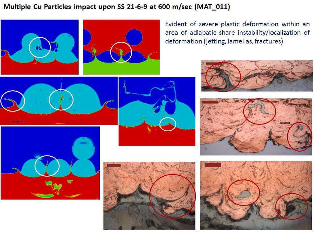
 at 0.099us Strain Rate at this region is about 10^5 (4.04x10^4) [1/s]. 2.")
 2.2x10^4 Johnson-Cook 4 0.099 us 4.")
5 CS Process characterization Maximum equivalent plastic strain copper side is 4.05 (740%) at 0.099us Strain Rate at this region is about 10^5 (4.04x10^4) [1/s]. 2.6x10^4 max PEEQ Time to max PEEQ Strain Rate max Temperature Steinberg us 9.79x10^4 (localization zone) 2.2x10^4 Johnson-Cook us 4.04x10^4 (localization zone) 2.6x10^4-320 C

6 Experimental Evident of Dynamic Recrystallization during HPCS
7 LPCS Process characterization


 Apparatus; ASTM C633: Standard Test Method")

8 Coating structures and properties characterization Applied Standards: MIL-STD-3021: Department Of Defense Manufacturing Process Standard - Materials Deposition, Cold Spray; ASME B31.4: Pipeline Transportation Systems For Liquid Hydrocarbons And Other Liquids (Chapter VII and VIII); API 650: Welded Steel Tanks For Oil Storage; API 653: Repair And Rework Of Existing Tanks; ASTM E1003: Standard Test Method for Hydrostatic Leak Testing; ASTM D1598: Standard Test Method for Time-to-Failure of Plastic Pipe Under Constant Internal Pressure; ASTM G69: Standard Test Method for Measurement of Corrosion Potentials of Aluminum Alloys; ASTM B117: Standard Practice for Operating Salt Spray (Fog) Apparatus; ASTM C633: Standard Test Method for Adhesion or Cohesion Strength of Thermal Spray Coatings; ASTM E384: Standard Test Method for Microindentation Hardness of Materials; ASTM E1588: E Standard Guide for Gunshot Residue Analysis by Scanning Electron Microscopy/ Energy Dispersive X-ray Spectrometry.


9 Mechanical properties characterization Adhesion tests were performed using Zwick/Roell Z150 according to ASTM C633 Coating thickness: ~250 m Test speed: 0.02 mm/sec Specimen size: 1 inch in diameter Cytec Engineered Materials FM 1000 Adhesive Film tm 50 BC2 coating layer CP1 coating layer F max, N/mm F max, N/mm Ave. 0 Ave. Interface breakup Surface breakup Typical Adhesive Failure, both Adhesive and Cohesion

10 Experimental Procedure Coating adhesion strength measurement
 Near interface Coating Layer Micro hardness testing was carried out on coated")


11 Mechanical properties characterization (DHV) 500 Near interface Coating Layer Coating Layer Coating Layer 400 Force (mn) Depth (um) Near interface Coating Layer Micro hardness testing was carried out on coated sample cross sections using a Shimadzu DUH-W201S micro hardness tester for Vickers Hardness with loading force of 500 mn Distribution of micro hardness along cross section (Ave. based on 3 measurement points) Al-25%Al2O3 Al-35%Al2O3 Zn-40%Al2O3 Al-20%Zn-30%Al2O3 Near interface Coating Layer Near interface Coating Layer Near interface Coating Layer Near interface Coating Layer HV Contact Elastic Module, Pa 5.83E E E E E E E E10

12 Anticorrosion properties characterization All electrochemistry measurements were made in accordance with ASTM standards using the Biologic SP-150 system. All sprayed samples were tested in the accelerated corrosion salt spray chamber ASTM B117 for a time period of up to 500 hours to obtain CORROSION KINETICS DATA Electrochemistry Cell REF: Ag/AgCl (3M KCl); CE: Pt; Solution: 1M NaCl (58.4gL^-1); N2 aerated for 15min prior each measurement; Corrosion Investigation Methods: Open Circuit Potential (OCP) DC Polarization (Tafel extrapolation) Zero Resistance Ammeter (ZRA) Electrochemical Impedance Spectroscopy (EIS)


")
13 MICROSTRUCTURE CHARACTERIZATION SEM images showing the cross-section microphotographs of the cold sprayed coating layers Al-based Coating (25%vol. Al 2 O 3 as in powder blend) Aluminium Coating Build Up composition
14 Main applications of LPCS Rapid repair/material build-up; Leak fixing/sealing; Corrosion protection of components; Uncommon repair.
15 RAPID REPAIR & LEAK FIXING/SEALING


16 Rapid Repair for body damage by LPCS The result of GDS process for Rt D-post severe ISD-unit f


17 Rapid Repair for the biggest to date cast Mg-based automotive part by LPCS Cold Shot

")

18 Rapid Repair for cast Mg-based part by LPCS Corrosion Potential (Ecorr) has to be matched with Ecorr of the base material
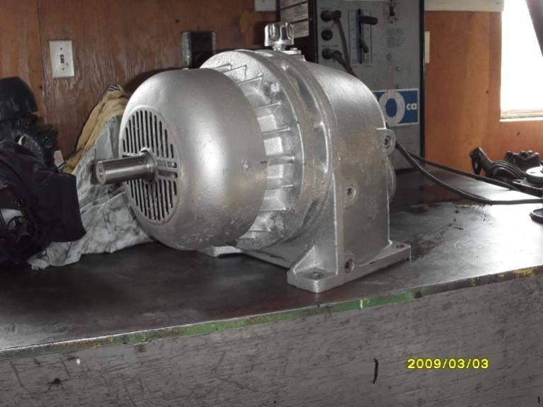
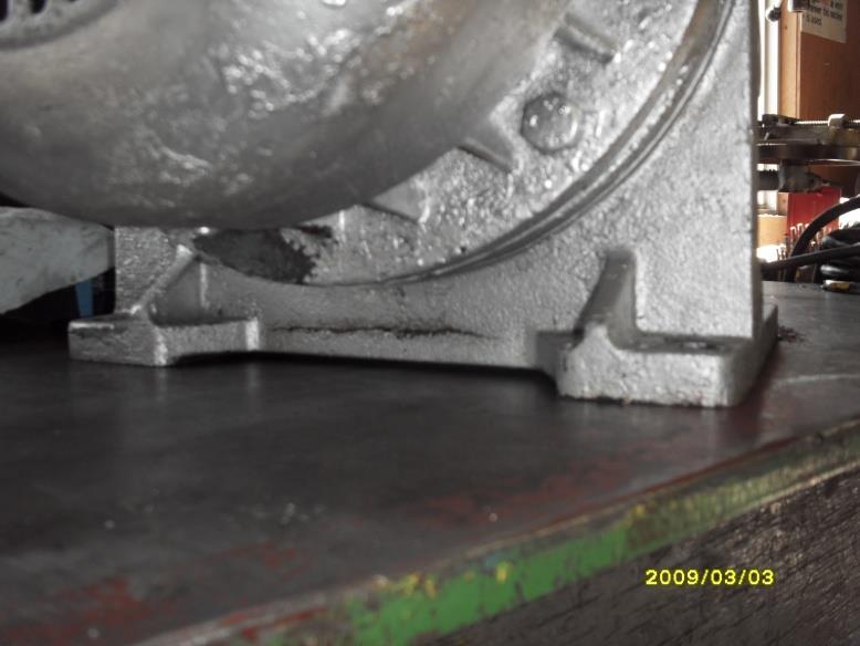
19 Application: Material Build up A crack in the cast iron housing Repaired area


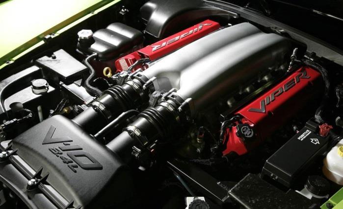
20 Application: Material Build up and Corrosion Protection The result of LPCS process for engine block rebuild The general view of the 4.7L Engine after corrosion test procedure
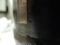
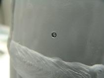

21 Application: Material Build up and Corrosion Protection Oil leakage Area with a Cold patch and protection against corrosion Procedure to fix 3mm hole in diameter
22 CORROSION PROTECTION
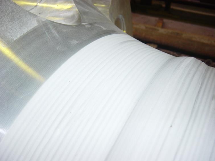
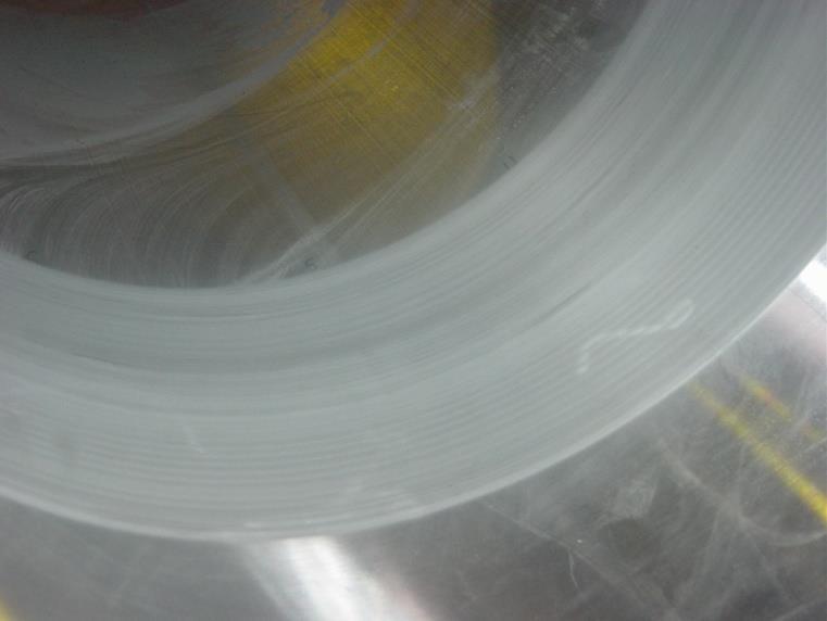
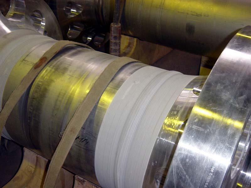
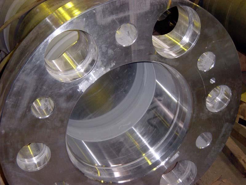
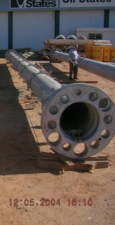
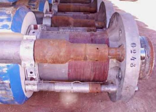
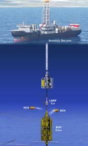
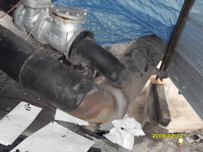
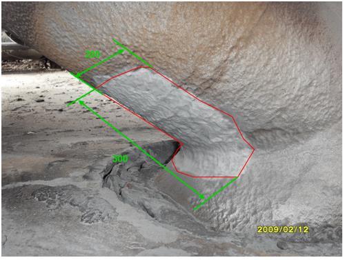
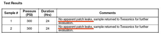
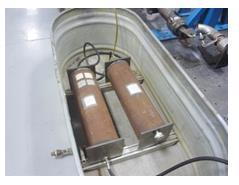
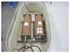
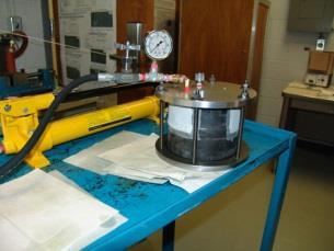
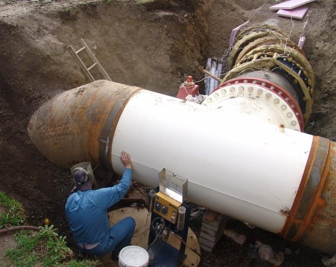
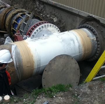
23 Application: Corrosion Protection of Deep Water Riser


")
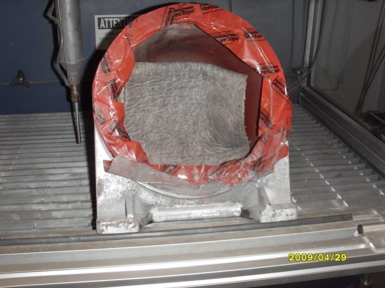
24 Application: Corrosion protection of welded seems LPCS coating layer (before and after corrosion test ASTM B117) Corrosion Protection of welded seams


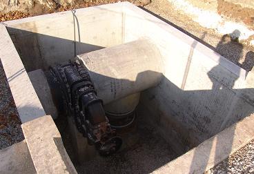
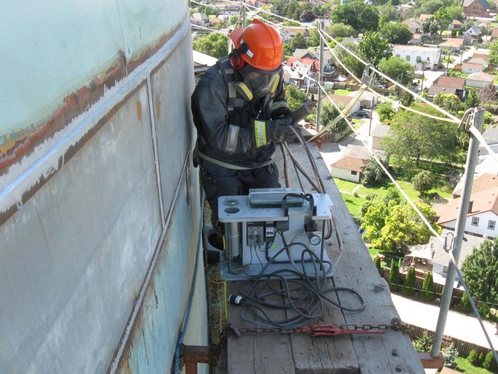
25 Application: Mobile Cold Spray Unit for in Field Repair Unit prototype Mobile LPCS unit
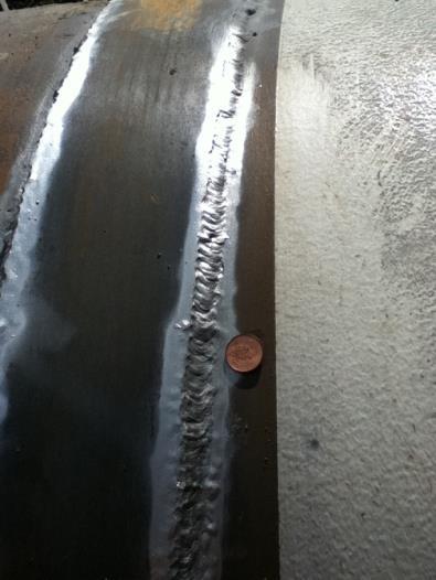
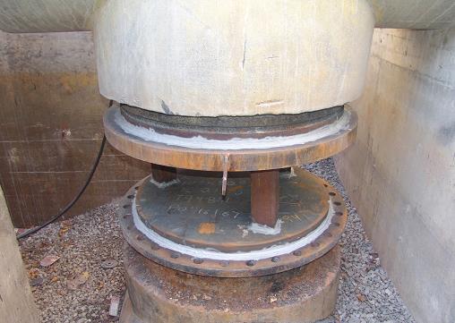
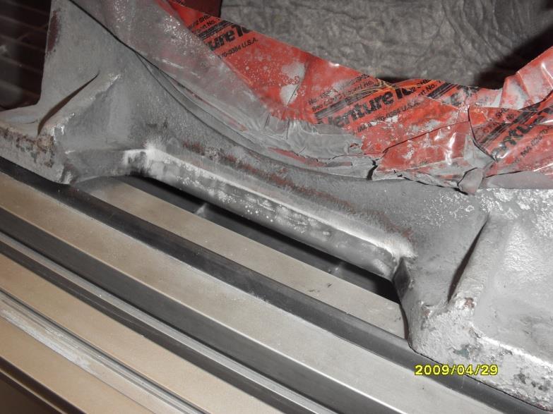
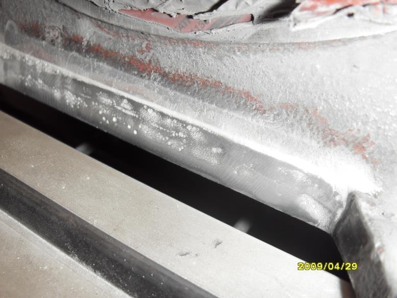
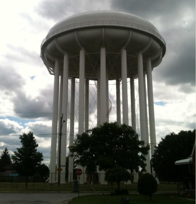
26 Application: Corrosion Protection of Welded Seems


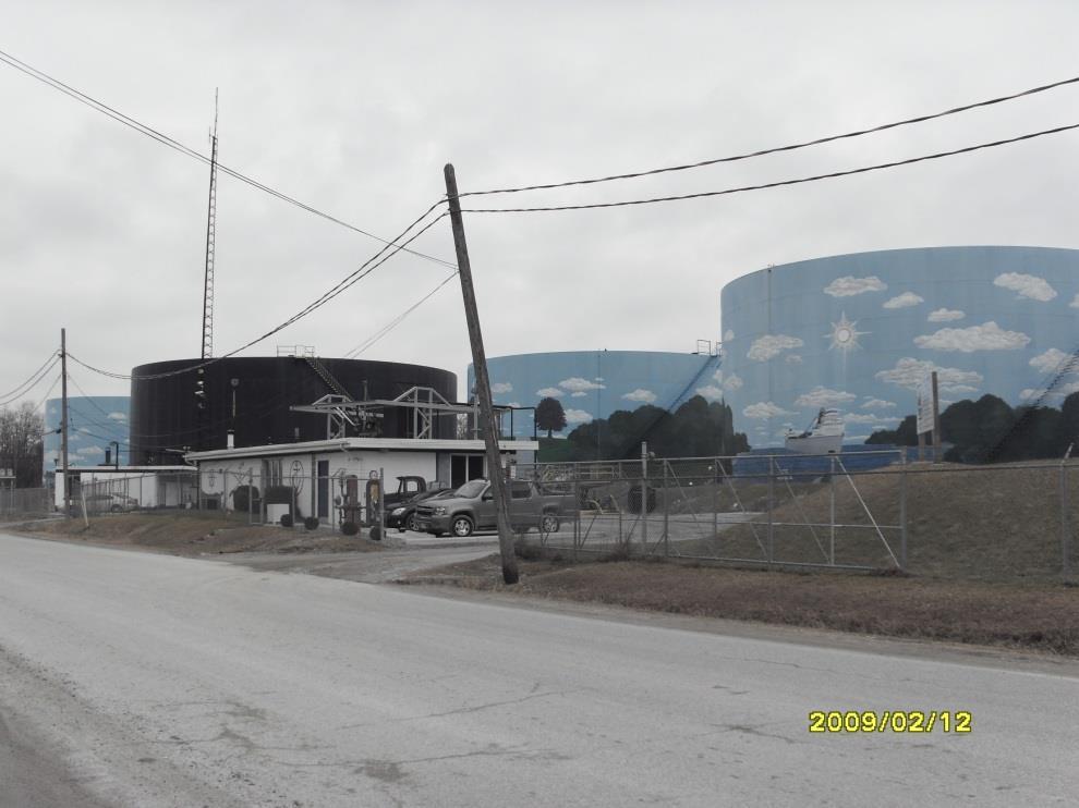
27 Application: Corrosion Protection of Welded Seems inside outside holes caused by corrosion (water level) severe corrosion at the water level

28 Application: Corrosion Protection of Welded Seems


29 Winsor, Ontario; Canada Corrosion at weld seem interface Severe corrosion damage
30 Thank You