EXPANSION OF JSW STEEL
|
|
|
- Gillian Murphy
- 5 years ago
- Views:
Transcription
1


2 EXPANSION OF JSW STEEL 16 MTPA to 18 MTPA JSW STEEL LIMITED, VIJAYANAGAR WORKS AT TORANAGALLU, DISTRICT BELLARY, KARNATAKA June 2018 Project Proponent


3 EXPANSION OF JSW STEEL 16 MTPA to 18 MTPA JSW STEEL LIMITED, VIJAYANAGAR WORKS AT TORANAGALLU, DISTRICT BELLARY, KARNATAKA June 2018 Project Proponent
4 CONTENTS Sl.No. DESCRIPTION PAGE NO. 1. Executive Summary Introduction of the Project Project description Site Analysis Planning Brief Proposed Infrastructure Rehabilitation & Resettlement Implementation schedule & cost estimate Analysis of proposal

5 List of Figures Figure no. Fig 3.1 Fig 3.2 Fig 3.3 Fig 4.1 Fig 6.1&2 Details Location of proposed facilities in the expansion project Plant lay out showing the location of proposed facilities Process flow for manufacture of finished steel products Road and Railway connectivity Location of proposed expansion of crude steel capacity List of Tables Table Details no. 1.1 New and proposed changes in facilities proposed 1.2 Proposed changes in existing facilities 1.3 List of facilities at 18 MTPA 2.1 India Steel consumption scenario (Million Tons) 2.2 Major market segments Major market segments Changes/Additional facilities in the proposed project 3.2 Optimization of facilities at 16.0 MTPA stage 3.3 Design basis of Pellet Plants 3.4 Typical analysis of raw materials for pellet production 3.5 Design basis of Blast Furnace 3.6 Typical raw material analysis (Dry basis) 6.1 List of species of plants/shrubs in and around JSWSL 8.1 Cost estimates : 18.0 MTPA expansion of crude steel at Vijayanagar 8.2 Cost estimates : Environmental control measures at 18.0 MTPA List of Annexures Annexure no. Details Annexure 1 Environment clearance for expansion from 10 MTPA to 16 MTPA, Dated : Annexure 2 Amendment for Environment clearance for expansion from 10 MTPA to 16 MTPA, Dated : Annexure 3 Amendment for Environment clearance for expansion from 10 MTPA to 16 MTPA, Dated : Annexure 4 Amendment for Environment clearance for expansion from 10 MTPA to 16 MTPA, Dated :
6 1 EXECUTIVE SUMMARY 1.1 INTRODUCTION JSW Steel ltd, formerly known as Jindal Vijayanagar Steel ltd. (JVSL), is the flag ship company of OP Jindal group of industries. This integrated steel plant at Toranagallu is the most modern, technologically efficient, eco-friendly and the largest integrated steel plant in India. JSW Steel ltd now intends to enhance the steel manufacturing capacity approved by MoEF&CC from 16.0 MTPA to 18.0 MTPA and produce a wide variety of steel products to meet the requirements of the customers. The expansion facilities will be built within the existing integrated steel plant complex. With this expansion, JSW Steel will be in a stronger position to supply a wide variety of steel products to the consumers in south and central India. The product mix that will be offered by JSWSL will then include semis like billets and blooms, flat products, long products, wire rods, re bars, light & heavy sections, and value added cold rolled and coated products. Over the years, JSWSL has grown from a crude steel capacity of 1.2 MTPA in 1999 to 10 MTPA by Currently, JSWSL is implementing its expansion plan of enhancing crude steel capacity from 10 MTPA to 16 MTPA approved by MoEF&CC vide environment clearance J-11011/489/2009 la-ii(i) dated 01 st October 2015 and subsequent amendments in 9 th June 2016 and 29 th May 2018 (Annexure-1 and Anneure-2). Some of the facilities which were originally belonging to JSWSL were developed as new entities with respective core expertise and the environment clearance was transferred to these companies vide amendment dated 28 th Feb 2018 (Annexure-3). The original proposal of expansion of crude steel capacity at Vijayanagar from 10 MTPA to 16 MTPA, primarily involved in setting up of two 3.0 MTPA Blast furnaces like the existing BF 3&4 units which were set up during the expansion of the steel plant from 4.0 MTPA to 10.0 MTPA. JSW Steel, Vijayanagar currently has an installed capacity of 12 MTPA crude steel. During , the crude steel production was 11.4 MTPA. As a part of its expansion program to enhance the capacity to 16 MTPA, JSW Steel is in the process of setting up additional facilities which will take the crude steel capacity to 13 MTPA by Dec However, with the upgradation of BF-1 and planned upgradation of BF-3 to country s largest blast furnace of 5560 m3 BF, the capacity of crude steel is 1-1
7 1 EXECUTIVE SUMMARY (cont d) being enhanced from 10 MTPA to 13 MTPA. JSW Steel is currently in the process of installing a similar Blast furnace of 5560 M3 capacity in India at Dolvi. Keeping in view of the advantages of larger blast furnaces and JSW Steel s own expertise developed over the years in operating large blast furnaces, it is proposed to install a large blast furnace of 5560 m3 in place of 4100 m3 blast furnace proposed in the original project of expansion of capacity from 10 MTPA to 16 MTPA. With this major change together with optimization of existing and proposed facilities, the capacity of crude steel is being enhanced from 16 MTPA to 18 MTPA. In the proposed expansion, new steel finishing facilities (BRM, WRM and Cold Rolling complex) and changes in the capacity and configuration of some production facilities (BF, BOF, EAF, HSM) is being proposed. The details are given in Table 1-1. Table 1-1 NEW AND PROPOSED CHANGES IN FACILITIES PROPOSED Production Facility 1 Pellet Plant-3 of 6.8 MTPA (in place of Sinter Plants 6) & SP-5 of 2.3 MT in place of 1.75 MTPA) 2 Blast Furnace-5 of 5500 m3 volume (in place of 4019 m3) 3 SMS-4 Larger size 350 T BOFs (from 2X200t to 2X350t) 3 Zero Power Furnace (in place of 1.2 MTPA EAF) 4 Hot Strip Mill-3 (enhancement from 3.6 to 5.0 MTPA) 5 Bar & Rod Mill-2(New) 6 Wire Rod Mill -2(New) 7 Cold Rolling Mill -3 of 2.3 MTPA capacity(new) 8 Larger capacity Lime and Dolo Calcining plants (from 8X300tpd to 4X600 tpd) (changes in configuration) 9 Oxygen Plants(new) 3 nos 10 New ash pond for gypsum(fgd) and bottom ash Over the years, there have been several changes in the quality of raw materials, improvements in operational practices and efficient management of resources by way of efficient use of energy, water and wastes. This has resulted in necessities to modify some of the existing facilities by relocation, 1-2
8 1 EXECUTIVE SUMMARY (cont d) reconciliation of capacities of production facilities and re configuration with ot any change in overall capacity of steel making. The details are given in Table 1-2. Table 1-2 PROPOSED CHANGES IN EXISTING FACILITIES 1 Facility Shifting of OBP-1(dry process) to OBP-2(wet Process) Remarks No change in overall capacity There are no changes in all other facilities both existing or those planned under the 16 MTPA expansion and yet to be executed. With the above, the list of facilities at 18 MTPA will be as follows and is presented in Table
9 Sl no 1 List of facilities as existing now after amendments and those proposed in the expansion to 18 MTPA Name of the Unit Ore beneficiation Plant - product Facilities at various stages of expansion in MTPA 4 -MTPA OBP-1 1 X MTPA OBP-2 1X 2.5, 1X 5.0 & 1 X 7.5, MTPA 2 Pellet Plants PP PP Nil 3 Sinter Plants SP1 4 Coke Oven NR 5 Coke Oven Recovery type 6 Hot metal Corex 7 Hot metal-blast Furnace CO 1 &2 2 X SP SP Nil Nil SP4-2.3 SP SP Dismantling of Existing NR Coke Oven Nil Coke CO 1&2-1.5 Corex 1 & 2 2X0.8 BF BF Nil BF 3 & 4 2 X 3.0 Nil BF BF At 16 MTPA 1 X 4.5 1X 2.5 1X X 7.5 PP 1 & 2 2 X 5.0 SP1-6 3X X X 1.75 Total Capacity (at 16 MTPA) Facilities Proposed (at 18 MTPA) OBP-1 facilities to be Relocated to OBP-2 PP SP-5: 2.3 SP-6: deferred in lieu of PP-3 Total Capacity ( at 18 MTPA) 0 0 No addition 0 CO 1-5 2X1.5 1X2.0 1X3.0 Corex X 0.8 BF 1-5 1X 2.5 1X X4.4 2X No addition No addition BF-5 of 3.0 MTPA to be built as 4.5 MTPA
10 1 EXECUTIVE SUMMARY (cont d) Sl no 8 9 Name of the Unit Pig Casting Machines (TPD) Crude steel - BOF, EAF & auxiliaries 10 Lime Kiln (TPD) Facilities at various stages of expansion in MTPA At MTPA MTPA MTPA MTPA Total Capacity (at 16 MTPA) Facilities Proposed (at 18 MTPA) Total Capacity ( at 18 MTPA) MGP-5000 tpd SMS LCP-1 4x300 SMS2 6.0 LCP-2 4X300,4X Slab Caster SMS2-6.4 SMS 3 & X200T BOF +2X1.2 EAF LCP-3 4 x 600 SMS-3-1 X1.6 SMS-4-1X3.6 SMS1-4 1X3.8 1X6.4 1X3.0 1X2.6 LCP X X 600 Slab Caster SMS-3: In place of 1 EAF, 1 ZPF is considered SMS-4 will be changed from 2 x 200T to 2 x 350T & will operate at 4.8 mtpa 7200 No addition SMS-4 slab caster changed from 1 x 3.6 mtpa to 2 x 2.5 mtpa 12 Billet caster Nil SMS-2 SMS HSM HSM 1 HSM-2 HSM-3 HSM1-3 HSM-3 upgraded to X4.0 1X5.2 1X Plate Mill Nil Nil Nil Nil Nil No addition Nil 15 Pipe Mill Nil 0.4 Nil 1X No addition Wire rod mill Nil WRM-1 WRM-2 WRM 1-2 1x X0.6, 1X No addition Rebar & Section BRM-1 BRM-1 New BRM-2 of 1.2 Nil Nil 1 mill 1X MTPA
11 1 EXECUTIVE SUMMARY (cont d) Sl no 18 Name of the Unit Cold Rolling Mill Complex Facilities at various stages of expansion in MTPA 4 -MTPA MTPA CRM CRM Galvanizing Lines Nil Nil MTPA Nil CGL-1-4X0.25 CGL-2-2X At 16 MTPA CRM1&2 4.1 CGL 1&2 4X0.25 2X0.45 Total Capacity (at 16 MTPA) Facilities Proposed (at 18 MTPA) Total Capacity ( at 18 MTPA) 4.1 CRM-3 of 2.3 MTPA No addition Color Coating Line Nil- 0.5 Nil No addition 0.5 CPP 1X100 Power Plant and CPP 3 &4 CPP 1-5 CPP-2 CPP5-1X process steam 2X300 1X100, 1X130, 1490 No addition X130 coal boilers in MW gas+coal 2X300,1X660 all gas 22 Incinerator (kg/hr) Nil 2 X 250kg/h 250kg/h 2 X 250kg/h 1000kg/h No addition 1000kg/h Slag Grinding and mixing unit Oxygen Plant (Out sourced) CP-1 1X 0.2 1x2500 TPD=2500 TPD Nil 2x1800 TPD + 1X900 TPD CP-2 1X2.0 2X1800 TPD CP-1&2 1X0.2 1X2.0 1 X 2500 TPD 4 X1800 TPD 1 X 900 TPD 2.2 No addition TPD 1 x 2060(TP) 2 x TPD 25 Township (nos) 2 Units 2 Units 2 units 6 units 6 units 1 unit 7 units 1-3
12 2 - INTRODUCTION OF THE PROJECT 2.1 IDENTIFICATION OF THE PROJECT & PROJECT PROPONENT India is the 3rd largest producer of crude steel globally with a total crude Steel Production of over 102 Mt in Indian economy is rapidly growing with special focus on infrastructure and construction, promoting further growth of steel industry JSW Group is a $ 12 billion leading conglomerate, with presence across India, USA, South America & Africa, the JSW Group is a part of the O.P. Jindal Group with strong footprints across core economic sectors, namely Steel, Energy, Infrastructure, Cement, Ventures and Sports. JSW Steel currently has a capacity of about 18 MTPA steel in its three steel plants located at Vijayanagar(Karnataka), Dolvi(Maharashtra) and Salem (Tamil nadu). JSW is also planning to enhance its capacity by scaling up existing plants and planning on installing new projects to produce 40 MTPA. Globally, JSW owns a steel plant, plate and pipe mill in the US, and mining assets in the US, Chile and Mozambique. JSW have integrated cutting-edge technology, innovation, R&D with sustainability and community initiatives in their journey of development. JSW Steel, Vijayanagar currently has an installed capacity of 12 MTPA crude steel. During , the crude steel production was 11.4 MTPA. As a part of its expansion program to enhance the capacity to 16 MTPA, JSW Steel is in the process of setting up additional facilities which will take the crude steel capacity to 13 MTPA by Dec The original proposal of expansion of crude steel capacity at Vijayanagar from 10 MTPA to 16 MTPA, primarily involved in setting up of two 3.0 MTPA Blast furnaces like the existing BF 3&4 units which were set up during the expansion of the steel plant from 4.0 MTPA to 10.0 MTPA. However, with the upgradation of BF-1 and planned upgradation of BF-3 to country s largest blast furnace of 5560 m3 BF, the capacity of crude steel is being enhanced from 10 MTPA to 13 MTPA. JSW Steel is currently in the process of installing a similar Blast furnace of 5560 M3 capacity in India at Dolvi. Keeping in view of the advantages of larger blast furnaces and JSW Steel s own expertise developed over the years in operating large blast furnaces, it is proposed to install a large blast furnace of 5560 m3 in place of 2-1
13 2 - Introduction of the Project (cont d) 4100 m3 blast furnace proposed in the original project of expansion of capacity from 10 MTPA to 16 MTPA. With this major change together with optimization of existing and proposed facilities, the capacity of crude steel is being enhanced from 16 MTPA to 18 MTPA. 2.2 Brief Description of the Nature of the Project The brief profile of the expansion project is as follows: Hot Metal MTPA Crude Steel MTPA Saleable products Hot Rolled Coils/Plates MTPA Cold rolled products 6.40 MTPA (Cold rolled annealed & galvanized coil, color coated coil. Tinplate coil, Silicon steel) Long Products (Bar, Wire Rod,) 4.00 MTPA The proposed production of crude steel and subsequent rolling would be accomplished via Blast Furnace (BF)-Basic Oxygen Furnace (BOF)-Caster route, followed by hot, cold rolling. The project falls under category A, Section 3 (a) of EIA Notification September 2006 and amendment thereof vide Notification No. S.O 3067 (E) dated 1 st December NEED FOR THE PROJECT AND ITS IMPORTANCE TO THE COUNTRY In , production of crude steel was about MTPA in the country with a growth of approximately 5.5% over India s per capita steel consumption is 61 kg, much lower than the global average of 208 kg. India s consumption of finished steel products has grown by 3.4 per cent in compared with With some of the measures taken by the Government, India has become a net exporter of steel products. Indian economy is rapidly growing with key focus on infrastructure and construction sector. Several initiatives mainly, affordable housing, expansion of railway networks, development of domestic shipbuilding industry, opening of defense sector for private participation, and the anticipated growth in the automobile sector, are expected to create significant demand for steel in the country. 2-2
14 2 - Introduction of the Project (cont d) Major factors which carry the potential of raising the per capita steel consumption in the country are listed below: Infrastructure improvement initiatives, such as Smart Cities project, 'Housing for All by 2022', Atal Mission for Rejuvenation and Urban Transformation (AMRUT), Manufacturing growth driven by Make-in-India initiative, Encouraging use of Made in India steel for various projects and levying of anti-dumping duties on certain steel products from Brazil, Russia, China, Korea, Japan and Indonesia. National Mineral Development Corporation expected to increase the iron ore production favoring steel production Emergence of the rural market for steel buoyed by projects like MGNREGS, development of Rurban Clusters under the Shyama Prasad Mukherjee Rurban Mission, Pradhan Mantri Gram Sadak Yojana, among others. As per the National steel policy (NSP) 2017, in order to achieve expected demand of 300 MT and per capita consumption of 160 kg of finished steel by , steel demand would need to grow at a CAGR of around per cent during the period against a CAGR of 3.5 per cent-4 per cent over the last 5 years. This would mean that capacity additions planned by most of the major steel players need to come on stream in next few years. As per NSP 2017, it is aimed to domestically produce value added steelproducts with focus on exploiting the existing iron ore deposits. These factors would emphasize on the need for the installation of the proposed projects. 2.3 DEMAND-SUPPLY GAP, IMPORTS VS. INDIGENOUS PRODUCTION, EXPORT POSSIBILITY & DOMESTIC/EXPORT MARKETS The total consumption of steel is estimated at MT in FY16. Driven by rising infrastructure development, growing demand for automotives and lower per capita consumption compared to international average, steel consumption is expected to reach 104 MT by the end of The consumption of steel during FY17 (Q1) was estimated at MT. World Steel Association (WSA) has 2-3
15 2 - Introduction of the Project (cont d) projected a growth of Indian steel consumption of 7.1% at MT in 2018, one of the highest growing among the global steel producers. The projected demand and capacity of finished steel products is as follows: Overall Steel, MTPA Demand Current Capacity Required Deficit Though the country has been traditionally a net importer of steel products all these years, the total export of finished steel increased by 16.7 per cent to million tonnes (MT) in , as against exports of MT finished steel during The projected demand of consumption of steel products is given below in Table 2-1 TABLE INDIA - STEEL CONSUMPTION SCENARIO (MILLION TONS) Item Crude Steel Capacity Crude Steel Production Finished Steel Production Domestic Demand Actual Forecast
16 2 - Introduction of the Project (cont d) Item Actual Forecast Exports The National Steel Policy (NSP) 2017 aims to increase export of steel and reduce import to nil by As of March 2017, the capacity utilization of steel producers is set to increase with strong export demand and signs of revival in domestic sales. Steel products find application in multifaceted sectors mainly dominated by areas of infrastructure & transport. Among the many drivers of demand, the following are having maximum influence in triggering consumption of finished steel products like Bars & Rods, Structural and Plates: 2-5
17 2 - Introduction of the Project (cont d) Product/Category Bars & Rods Structural Plates HR Products CR Products Galvanized,Coated, Tin Plate, Silicon Steel (NGO) Application Infrastructure - House Building Fasteners & Wires Bright Bars Infrastructure - High rises Industrial Construction Infrastructure Bridges Railways - Wagons, Coaches, Tankers Industrial Construction Defence Production Energy - Boilers, Pressure Vessels, Penstocks Tube making industry Railways - Wagon & Coach Automobiles Industrial Machinery White goods - Refrigerators, Air-conditioners Automobiles Silos & Containers Precision Tubes Furniture Automobiles Consumer durables Food Industries Electrical Appliances & machine Construction Packaging & Furniture The NSP 2017 provides an overview of the segmental composition of the projected Indian market for the year with quantitative estimates of the likely demand and their associated growth rates adopted for the study. A summary of the leading segments of the domestic market is furnished in the Table 2-2 and Table 2-3 below. 2-6
18 2 - Introduction of the Project (cont d) TABLE MAJOR MARKET SEGMENTS Market Segments Demand (Million Tons) % Share Infrastructure (Project Construction) Construction (Real Estate & Buildings) 90 39% 45 20% Engineering & Fabrication 43 19% Energy 11 5% Automotive 10 4% Sub-total (Major Segments) Other Segments (Railways, Ship Building, Defence, Gas Pipelines, Packaging etc.) % 31 13% Total % TABLE MAJOR MARKET SEGMENTS Market Segments Annual Growth (%) Infrastructure (Project Construction) 16% Oil & Gas Pipelines 11.3% Defense 9.8% Automotive 9.7% 2.4 EMPLOYMENT GENERATION DUE TO THE PROJECT In the construction & operation phases of the proposed project, both direct & indirect deployment of local work force would be facilitated. The nature 2-7
19 2 - Introduction of the Project (cont d) of employment opportunities would involve contractual & casual labor work for semiskilled & unskilled local skilled staff and direct employment for skilled locals. It is estimated that there would be a requirement of around casual and contract workers, during the phase of construction. Subsequently in the operation phase, approximately 1200 employees would be directly employed. 2-8
20 3 - PROJECT DESCRIPTION 3.1. TYPE OF PROJECT INCLUDING INTERLINKED PROJECT The proposed project is a brown field expansion project involving the expansion of crude steel capacity of the integrated steel plant of JSW steel at Vijayanagar from 16 MTPA to 18 MTPA, within the existing land area available with JSW Steel. The increase in capacity is being planned by installation of large capacity Blast furnace and improvement in productivity in some of the existing manufacturing facilities, with consequent reduction in overall pollution LOCATION JSW Steel, Vijayanagar is located at Toranagallu, Sandur Taluk, Ballari district in the state of Karnataka. The existing integrated steel plant of JSW Steel limited is situated between 15 o 10' - 15 o 12' N latitude and 76 o 38' - 76 o 40'E longitude. The steel plant is located at 29 km from Bellary, 33 km from Hospet and about 340 km from Bangalore by road. Nearest railway station to the steel plant is Toranagallu. Broad gauge railway lines between Guntakal and Hubli are passing through this station. The eastern port of Chennai is 460 km and western port of Goa is 430 km. A glimpse of the location of the steel plant; lay out of the plant; photograph of existing plant; location of proposed facilities in the expansion project is shown in Fig DETAILS OF ALTERNATE SITES CONSIDERED AND THE BASIS OF SELECTING THE PROPOSED SITE The expansion of crude steel capacity is being planned by upgrading capacity of existing blast furnaces during their campaign repair and installation of a 4.5 MTPA large capacity blast furnace in place of a smaller furnace of 3.0 MTPA. This is a brownfield expansion, within the available land area and utilizing existing infrastructure. Alternative site was not examined. 3-1


21 3 - Project Description (cont d) Pla FIG SITE LOCATION MAP 3-2


22 3 - Project Description (cont d) 3.4. SIZE OR MAGNITUDE OF OPERATION The proposed project after its completion will facilitate in production of 18.0 MTPA of crude steel along with value added long and flat steel products to meet the increasing demand of the customers and country`s infrastructure development. The proposed facilities will be set up in an area of about 450 acres within the existing steel plant complex. 3.4 LAYOUT The plant lay out showing the location of the proposed facilities is shown in Fig-3.2 Fig-3-2 Location of Project site and surrounding 10 km area 3.5. PROJECT DESCRIPTION WITH PROCESS DETAILS The basis of earlier expansion of crude steel capacity from 10 MTPA to 16.0 MTPA was based on the premise of installing two Blast Furnaces each of 3.0 MTPA. However, the first 3.0 MTPA expansion from 10 MTPA to 13 MTPA has been realized by augmenting the capacity of BF-1 and BF-3 during their respective campaign repairs. The BF-1 capacity has been enhanced from 0.9 MTPA to 2.5 MTPA and BF-3 from 3.0 MTPA to 4.5 MTPA by installing the Country`s largest Blast furnace of 5560 m3, expected to be commissioned by Dec JSWSL is also in the process of setting up a similar capacity Blast furnace at its Dolvi unit, the first such furnace in India. Considering the advantages of large capacity Blast furnaces, in terms of higher productivity, energy efficiency and environment friendliness, it is now proposed to install a 4.5 MTPA Blast furnace in lieu of BF-5 of 3.0 MTPA proposed at the 16 MTPA stage of expansion. This will lead to enhancing the capacity from
23 3 - Project Description (cont d) MTPA to 17.5 MTPA (in place of 13 MTPA to 16.0 MTPA as proposed earlier). Further, due to optimization in some of the existing Blast furnaces due to changes in iron ore quality, the overall hot metal production including from two Corex units works out to Mtpa. Accordingly, it is proposed to enhance the crude steel production to 18.0 MTPA, as against the 16.0 Mtpa planned earlier. The proposed production of crude steel and subsequent rolling would be accomplished via Blast Furnace (BF)-Basic Oxygen Furnace (BOF)/Zero power furnace(zpf)-caster route, followed by hot & cold rolling for production of flat & long products. The highlights of the proposed expansion are: a. Installation of the largest blast furnace of the country to produce 4.5 MTPA of hot metal (in place of a smaller capacity Blast furnace of 3.0 MTPA proposed in the 16 MTPA expansion) b. Installation of Zero Power furnace(zpf), for manufacturing steel from hot metal & DRI, without use of electrical energy (in place of Electrical Arc Furnace.) c. Augment the capacity of BOF from 200 T capacity to 350 T capacity d. optimization in some of the existing BF units due to changes in iron ore quality. e. Installation of 5.0 MTPA HSM in place of 3.6 MTPA unit an new 2.3 MTPA CRM-3 The flowsheet of manufacturing steel is shown in Fig-3.3.(See last page) The changes or additional facilities proposed in the expansion and optimization being carried out in the 16 MTPA units in the propose project to produce 18 MTPA of crude steel and associated finished products are given in Table 3-1. and Table 3-2. However, there are no changes in the overall capacities of following units as proposed in the 16 MTPA stage even at 18.0 MTPA stage. 1. Ore Beneficiation plant : 19.5 MTPA 2. Coke ovens : 8.0 MTPA 3. DRI(Gas based) : 1.2 MTPA 4. Lime Kilns : 7200 tpd 5. Water allocation : 72 MGD 6. Thermal Power Plant : 1490 MW 3-4
24 3 - Project Description (cont d) TABLE 3-1 CHANGES / ADDITIONAL FACILITIES IN THE PROPOSED PROJECT Capacity, Facility MTPA 1 Pellet Plant-3, in place of Sinter Plants 6 of 5.75 MTPA) Additional Sinter Plant of 2.3 MTPA in place of SP-5 of 1.75 MTPA 0.55 MTPA 3 Additional Blast Furnace-5 of 5500 m3 volume (in place of 4019 m3) 1.5 MTPA 3 Additional SMS-4 Larger size BOFs(2X200t to 2X350t) 2.2 MTPA 4 No change in Zero Power Furnace(in place of 1.2 MTPA EAF) capacity 5 Additional Hot Strip Mill-3 (enhancement from 3.6 to 5.0 MTPA) 1.4 MTPA 6 Bar & Rod Mill-2(New) Wire Rod Mill -2(New) Cold Rolling Mill-3 (New) x 2060 tpd Oxygen Plant(New) 2X2200 tpd 10 Ash Pond for Gypsum (FGD) and bottom ash 1 unit TABLE 3-2 OPTIMISATION OF FACILITIES AT 16.0 MTPA STAGE 1 2 Facility Relocation of OBP-1 to near OBP-2 Shifting of OBP-1(dry process) to OBP-2(wet Process) 3 Larger capacity Lime and Dolo Calcining plants (from 8X300tpd to 4X600 tpd) Remarks No change in overall capacity No change in overall capacity No change in overall capacity The production facilities would be adequately supported by necessary modifications if required in the auxiliary facilities such as raw materials unloading and storage, proportioning of raw materials, electric power receiving and distribution stations, various utility facilities, water treatment and distribution system, etc. 3-5
25 3 - Project Description (cont d) The following write-up gives the details of the additional/modified process units which are being proposed in the 18.0 MTPA expansion Ore Beneficiation Plant: There are two Ore beneficiation plants existing with a capacity to produce 19.5 MTPA of iron ore concentrate. The OBP-1, which was installed during the 4.0 MTPA stage of steelmaking was based on dry grinding of iron ore in three ball mills to produce green pellets. In view of heavy dust pollution during grinding, all the new beneficiation units installed in the OBP-2 area were based on wet grinding. The slurry after grinding is thickened and filtered in special filters to produce pellet feed for the pellet plant. The OBP-1 unit with dry grinding is planned to be shifted to OBP-2 area with wet grinding. The iron ore concentrate slurry is pumped to PP-1, where the slurry is filtered and used for pellet production. The proposal is to shift the unit to OBP- 2 area. There is no change in the overall capacity of the OBP units, which is 19.5 Mt of beneficiated product Pellet Plant The blast furnace burden will comprise of 42.5% sinter. 37.5% pellet and 20% C-Ore. Pellet is also required for production of DRI in the gas based DRI plant and as feed material in Corex 1&2. Currently the existing PP-1&2 have an installed capacity each of 5.0 MTPA and are producing pellets at a rate of 4.0 MTPA each. To meet the total requirement of pellets at 18.0 MTPA stage, it is envisaged that one pellet plant of 6.8 MTPA capacity would be installed. Pellet requirement for DR plant, Corex and blast furnaces would be met from these three pellet plants. The new large capacity pellet plant is being built in lieu of Sinter Plants 5 & 6, to reduce pollution from sintering process. Design basis: The design basis considered for pellet plant is given in Table 3-3. TABLE DESIGN BASIS OF PELLET PLANTS Item Value Number of units, Nos. 1 Gross pellet unit, MTPA 6.8 Screening, % - at BF stock house 10 Operating days/year 350 Grate area4(w) X 204(L) M
26 3 - Project Description (cont d) No of Balling discs for green pellet/dia 14Nos / 7.5M Dia Mixed Gas Fuel Used/CV 1850 Kcal/Nm3 Hood exhaust volume m3/h 28,00,000 Wind box exhaust volume m3/h 13,00,000 The typical analyses of input raw materials (dry basis) for pellet production are given in Table 3-4. TABLE TYPICAL ANALYSIS OF RAW MATERIALS FOR PELLET PRODUCTION Fe SiO 2 Al 2 O 3 CaO MgO LOI % % % % % % Iron ore > concentrate Limestone Dolomite Lime Flue dust Coke breeze The indicative chemical analysis of pellet produced would be as follows: Fe, %.. >62% CaO/SiO 2 ratio % Al 2 O 3, % MgO, % The envisaged physical and metallurgical properties of sinter would be as follows: Size range mm Compressive strength kg/pellet Tumbling index +6.3 mm.. 92% -500 micron.. 6% 3-7
27 3 - Project Description (cont d) The pellet plant would comprise following facilities: - Slurry storage and filtration units - Storage and handling of iron ore and return fines - Storage, handling and preparation of coal, dolomite and bentonite - Proportioning and mixing - Balling for production of green pellets - Induration and cooling - Product screening - Product pellet storage - Auxiliary facilities laboratory etc. - Process and Plant de-dusting system - Cranes, hoists and elevator - Plant electrics - Instrumentation and Level- 1 - Plant communication system - Utility system - Air-conditioning and ventilation system - Fire fighting system 3-8
28 3 - Project Description (cont d) Blast Furnace The requirement of hot metal for Steel Melt Shop at 18.0 MTPA would be around MTPA. The hot metal will be met from the following units: - Corex1&2 : 1.6 MTPA (installed in inception of the plant) - BF-1 : 2.5 MTPA (Upgraded during campaign repair) - BF-2 : 2.17 MTPA (Installed at 4 MTPA stage) - BF-3 : 4.4 Mtpa (To be upgraded in 2019 from 4019 m3 to 5360 m3) - BF-4 : 3.0 MTPA - BF-5 : 4.5 MTPA (Planned to install in lieu of 3.0 MTPA unit) The blast furnace BF-3 and the new BF-5 (in lieu of small BF of 4019 m3) would incorporate all the modern technological features. The design basis of blast furnace is given in Table 3-8. TABLE DESIGN BASIS OF BLAST FURANCE Item BF-5 at 16 MTPA BF-5 at 18 MTPA No. of furnaces 1 1 Volume, cu m (approx.) ,360 (U.V) Operating days Burden: Sinter, % Pellet, % Ore, % O2 enrichment, % 8 8 Coke rate (including nut), Kg/thm Coal rate, Kg/thm Slag rate, Kg/thm Coke ash, % Si in metal, % to 0.7 Capacity of TRT in MW No of cast houses 4 4 Blowers (2W+1SB) m3/min Slag granulation capacity in ton per min 6 8 Design of dust catcher Cyclone Cyclone Cast House FE system (2 ns) each
29 3 - Project Description (cont d) Stock House De-dusting system m3/h 7,56,000 15,05,000 The major raw materials for blast furnace comprise iron ore, sinter, pellet, additives and coke from the Coke dry quenching unit. Pulverized coal would be injected through tuyeres as auxiliary fuel in blast furnace. The typical analysis of raw materials envisaged is given in Table 3-9. TABLE TYPICAL RAW MATERIALS ANALYSIS (DRY BASIS) Fe SiO 2 Al 2 O 3 CaO MgO % % % % % Sinter Pellet Sized ore Quartzite Limestone Dolomite The plant comprises following facilities: - BF proper - Cast house - Slag granulation plant - Hot blast stoves - Gas cleaning plant - Stock house and charging system - Hot metal handling system - Cranes and hoists - Coal dust injection system - Hot metal granulation and ladle repair shop - Stock house & Cast house de-dusting system - Air blowing system - Plant electrics - Instrumentation, automation and control system - Communication system - Water system - Utility system - Fire fighting system - Air conditioning and ventilation system 3-10
 Profile of BF-5 (4.5 MTPA) 3.5.4 STEEL MELT SHOP Currently, JSW Steel has three Steel melt Shops.")
30 3 - Project Description (cont d) The granulated BF slag would be used for manufacture of cement by JSW Cement. The profile of the 3.0 MTPA and 4.5MTPA Blast furnaces are given below Profile of BF-5 (3.0 MTPA) Profile of BF-5 (4.5 MTPA) STEEL MELT SHOP Currently, JSW Steel has three Steel melt Shops. SMS-1: The shop had 3 BOF converters of 130 T capacity, which has been upgraded by modifications in lining design to produce 132 T per heat, thus producing 4.0 MTPA of liquid steel. SMS-2: The shop had 4 BOF converters of 175 T, which has been upgraded by volume enhancement to 180 T per heat, thus producing 6.4 MTPA of liquid steel. SMS-3: The shop has one EAF of capacity 150 T to produce 1.2 MTPA of liquid steel. EAF utilizes DRI and hot metal to produce liquid steel. There is a provision for another similar EAF at the 16 MTPA stage and is yet to be constructed. 3-11
31 3 - Project Description (cont d) To handle the additional quantity of hot metal due to enhancement of capacity of BF-5, the following changes are proposed at 18 MTPA stage. SMS -1 & 2: No change SMS-3 : The EAF-2, which is yet to be installed is proposed to be changed to Zero Power Furnace(ZPF). This is like EAF but utilizes a larger portion of hot metal and less DRI. The electrodes are dispensed away and the energy for steel making is provided by oxygen injection. This unit has capability to produce 1.5 MTPA of liquid steel from each shop. The details of EAF, currently operational and the proposed ZPF is given below in Table 3. Sl.No Descriptions UOM EAF ZPF 1 Heat Size Ton HM Input % DRI Input % Tapping Temperature deg.cen Metallic Charge t/heat T Hot Metal t/heat T Hot Metal t/day T ,744 8 Coolant (gas based DRI) t/heat T Coolant (gas based cold DRI) t/day T , Electrical Energy Consumption kwh/tls Oxygen Consumption Nm3/tls Electrode Consumption kg/tls Burnt Lime & Dolo Lime kg/tls Slag kg/tls Oxygen Blowing min Production time/eaf Day/Year No of Days Yearly Production/EAF Mtliq/year MTPA Type of Lance SIS3.0 SIS No of Lance No Total oxygen blowing capacity Nm^3/Hr Tap to Tap time Mins Primary & Secondary FE System m3/h 25,00,000 28,00,000 SMS-4: In the 16 MTPA stage expansion, this shop was designed to have 2X200 T BOF Converters to produce 2.6 MTPA of liquid steel. With the necessity to 3-12
32 3 - Project Description (cont d) handle additional hot metal, the size of the BOF Converters has been enhanced from 200T to 350 T. The 350 T BOF can feed liquid steel to slab caster for higher productivity. The technical details of 200 T BOF as proposed earlier at 16.0 MTPA and 350 T BOF as proposed now at 18 MTPA is given in Table 3- SMS-4 (at 16.0 MTPA) SMS-4 (at 18.0 MTPA) 1 No. of converters installed 2X200 2X350 2 Converter operation, days/year Liquid steel production per day, tons Considering converter availability and utilization, No. of converters operating Liquid steel production per day 4 per operating converter, tons Average tap-to-tap time(min) No. of heats/day/converter Liquid steel required per heat, 7 tons Selected heat size, tons liquid 8 steel Type of ladle for hot metal 9 transport Torpedo Torpedo 12 GCP wet or dry Wet GCP Dry GCP 13 Capacity of GCP 300,000Am3/hr 500,000Am3/Hr 14 Secondary FE system, volume 50,00,000 Am3/hr 55,00,000 Am3/hr Gas holders nos and capacity 15 (one) 50000m m3 16 No of boosters & capacity 2w+1 stand by 3w+1 stand by 17 Casters 4 2 Slab caster; capacity & size Slab Caster details two 1600 mm casters two 2200 mm twin slab caster 19 Heat size, tcs 200 T 350 T 20 Reference slab size for calculation , Reference casting speed, m/min meter /min 3-13
33 3 - Project Description (cont d) 22 Throughput, tons/min. 4.5T/Min per strand 9Tons 23 Average casting time, min. 55min 50 min 3 heats to 40 No. of heats in sequence 6 heats to 75 heats 24 heats 25 Preparation time, min. 90min 90 min Lime Calcining Plant At 16.0 MTPA production stage of crude steel, it was envisaged that eight lime Calcining plant and dolomite calcining plant of 300 TPD would be installed to produced calcined lime and dolo, sufficient to cater to the demand of calcined lime/dolo of the steel melt shops. However, considering the advantages of 600 tpd kilns, the configuration will be changed from 8X300 tpd to 4X600 tpd. It may be noted that the 600 tpd TSR kilns of Cimprogetti was installed for the first time in the world. Over the years, the technology has been perfected by JSW Steel Rolling Mills The following mills would be installed with production capacities as follows: Mills Hot Strip Mill (HSM-3) Rebar mill (BRM-2) Wire rod mill (WRM-2) Cold Rolling Mill(CRM-3) No. and capacity 1 x 5.0 MTPA in lieu of earlier 3.6 MTPA 1 x 1.2 MTPA (New) 1 x 1.2 MTPA (New) 1 x 2.3 MTPA (New) Hot Strip Mill (HSM): Each hot strip mill would be designed for a production of 5,000,000 tons/year of HR coils. Input: Cast slab would be used as input for the hot strip mill. Width, mm Thickness, mm Length, mm.. 11,000 Unit weight (max), kg.. 40,000 Finished product: The HR coil size would be as follows: 3-14
34 3 - Project Description (cont d) Width, mm Thickness, mm Coil weight (max), ton.. 40 Mill yield, %.. 98 Each hot strip mill would comprise of the following facilities: - Walking beam type reheating furnaces - Primary hydraulic descaler - One (1) 2-Hi roughing stand with attached edger - One (1) 4-Hi roughing stand with attached edger - Crop shear - Secondary hydraulic descaler - Seven(7) 4-Hi finishing stands - Run-out roller table - Laminar cooling system - Down coilers - Walking beam coil conveyor system Double Side Trimming Shear Slitting shear Dividing Shear Cold Plate Leveller Pile transfer Heat treatment facilities Rebar Mill(RBM): 1,200,000 tons/year. The rebar mill would be designed for production of Input: Continuously cast billets of following size would be used as input to the rebar mill: Section, mm x 150 Length, mm Finished product: Output from rebar mill would be as follows: Size mm dia. rebars Cut to length m Mill yield, %
35 3 - Project Description (cont d) The mill would comprise of the following major facilities: - Billet Charging grids - Walking beam type reheating furnace - Roughing train and intermediate train - Shears - No twist blocks - Water boxes and troughs - Cooling beds with high speed entry equipment - Cold shear - Chain transfer - Bundle strapping machines - Bundle unloading stations Wire Rod Mill(WRM): The Wire rod mill (WRM) would be designed for production of 1,200,000 tons/year. Input: Continuously cast billets of following size would be used as input to the WRM: Section, mm x 150 Length, mm Finished product: Size mm dia Mill yield, %.. 97 The mill would comprise of the following major facilities: - Charging grids - Walking beam type reheating furnace - Descaler - Single strand high speed roughing mill - Double strand intermediate mill train - Shears - Pre-finishing mills - Wire rod blocks - Reducing and sizing blocks - Water boxes and troughs - Laying heads and pinch rolls 3-16
36 3 - Project Description (cont d) - Air cooling conveyors - Reform station with ring distribution - Coil conveyor Cold Rolling Complex: an identical cold rolling mill complex like CRM-2 would be installed to produce cold rolled annealed, galvanized coils. The complex would comprise of the following process units: Cement Grinding Unit The additional granulated slag generation will be about 0.8 MTPA. JSW Cement has surplus capacity at their Vijayanagar Plant to consume this amount of slag for Portland slag cement making. The clinker required to produce cement would be procured from outside the plant Captive Power Plant JSW Steel has following facilities for a total generation of 936 MW. - Captive thermal power plants: CPP-1 : 100MW, CPP-2 : 130 MW CPP-3&4 : 600 MW CPP-5 : 660 MW (to be installed later) TRTs of BF1,3&4: 30 MW CDQ : 76 MW Further the following power generating units are being installed CDQ : 98 MW (CDQ of Coke 5&6(rebuilt battery of Coke1&2) TRT : 42 MW (27 MW from BF-5 & 15 MW incremental of BF-4) Total : 1076 MW Gross. Net 975 MW The electrical power requirement at 18 MTPA stage has been worked out to be 1412 MW. The balance electrical power will be met from JSWEL which has an installed capacity of 860 MW. To have stability of the system, the power system will be connected to the grid and in case of any shortage, it will be drawn from the grid. JSWSL has an approval for a CPP-5 of 660 MW thermal power plant at 16 MTPA stage of expansion. This facility will be set up later. 3.6 RAW MATERIALS Sources of Raw Materials The probable sources of major raw materials (indigenous/imported) for meeting the production requirements are given below. Major Raw Materials Mode of transport 3-17
37 3 - Project Description (cont d) Iron ore fines/lumps/clo Coking coal PCI coal Limestone(SMS grade) Fluxes Other additives Rail/Road/ Pipe conveyor Sea/Rail/Road Sea/Rail/Road Sea/Rail/Road Rail/Road Sea/Rail/Road The plant would produce both long and flat products, which would have potential for sale in national as well as international markets. The estimated annual requirements of major raw materials at 18.0 Mtpa is presented below. Sl. No. Major Raw materials Estimated Quantity, tons 1 Coking Coal 8,340,000 2 Iron ore (Lump) 7,310,000 3 Iron ore fines (Medium grade) 24, 100,000 4 Iron ore fines(high grade) 1,500,000 5 PCI coal 3,320,000 6 Limestone 6,350,000 7 Dolomite 3,500,000 8 Steam coal 1,500,000 9 Bentonite 150, Quartzite 370, Pet Coke for Coke ovens 900, RESOURCE OPTIMIZATION/RECYCLE & REUSE ENVISAGED IN THE PROJECT The plant has been designed with state-of-art technology for optimum consumption of energy & other resources. By product fuel gases would be reused within the plant as in-plant fuel and also to produce power in the CPP. Corex gas/coke oven gas would be used as reductant to produce DRI. In addition, adopting a compact layout for the Plant would enable to optimise the utilisation of land, which is another critical resource. By utilising the fines and scrap generated during the process within the plant for the production process, usage of raw materials is optimised. Water consumption would also be optimised 3-18
38 3 - Project Description (cont d) by treatment of water to the extent possible and recycle of treated water as make-up in the network. Solid byproducts would be reused to the extent feasible. BF slag and fly ash would be used to produce cement in captive cement manufacturing unit. 3.8 AVAILABILITY OF WATER AND POWER Water JSW Steel receives the make-up water from two sources, viz Tunga Bhadra Dam (32 MGD through pipeline of 35 KM) and Alamatti dam (40 MGD through a pipeline of 178 Km). This allocation of a total of 3,30,000 m3/day was obtained during the expansion of the steel plant from 4.0 MTPA to 10.0 MTPA. In the expansion of capacity from 10MTPA to 16 MTPA, no additional allocation was sought. The total water requirement at 18 MTPA will be as under: Steel plant : 1,44,000 m3/d Captive power plant & JSWEL : 93,000 m3/d Township : 24,000 m3/d Losses & Evaporation : 40,000 m3/d Total for JSWSL complex : 3,01,000 m3/d The recovery of water from the existing seven RO Plants is 22,000 m3/d. Further, additional 8400 m3/d of RO permeate will be recovered from the ZLD plant of Coke-5 and a centralized RO plant. JSWSL has established a Total water management approach, as a result the water is extensively used by cascading from one process to another, ensuring zero discharge plant. The existing water allocation of 3,30,000 m3/d is sufficient to meet the requirements of the expansion up to 18.0 MTPA stage. 3.9 Power The estimated power requirements of various plant units including utilities and auxiliary facilities for the Plant at 18.0 Mtpa works out 1412 MW. The available power from captive and from JSWEL is 1735 MW. Thus, there is adequate availability of power for the steel plant operations at 18 MTPA stage. DG sets of adequate capacities are proposed for the plant units as well as CPP auxiliaries to cater to the requirement of safe shutdown and safety of personnel during total black-out condition when power supplies to plant network from both the sources viz. grid and CPP have failed. 3-19
39 3 - Project Description (cont d) 3.10 WASTE GENERATION AND MANAGEMENT Wastewater generation & Management Currently, the integrated steel plant complex of JSW Steel, at Vijayanagar is a Zero Liquid Discharge plant, the only steel plant of this in the world. This has been achieved through the following measures - Technologies which conserve water - Recycle of > 95% treated water back into the process after treatment using specialty chemicals. - Cascaded use of water where blow down from one unit is used as make up in another unit - Reuse of treated sewage as industrial make up - Recover good quality water by installing RO Plants. Till now 7 RO plants are in operation recovering 21,000 m3 of water per day. - ZLD Plants with a combination of RO plant with evaporator for 100% recovery of water. - Use of high TDS water in quenching applications. It is estimated that about 1000 m3/h of waste water and blow down water will be generated in the proposed expansion to 18 MTPA stage. This wastewa ter will be treated in the following units: - A 300 m3/h ZLD Plant at Coke ovens to treat treated waste water from BOD Plant to achieve zero liquid discharge. - Two RO Plants to recover RO permeate, each of 500 m3/h, one near OBP and another near SMS-4. The RO rejects will be used in slag quenching and dust suppression in RMHS. It is proposed to have ZLD at 18 MTPA stage of the plant, preventing any pollution of the receiving environment Solid Waste Management The estimated generation of major solid wastes at 18 MTPA stage is tabulated below: Solid wastes Expected generatio n at 18 MTPA Management Scheme MTPA BF Slag 7.2 Granulation in Slag granulation plant of BFs and used in cement manufacturing in JSW cement plant. About 3% of the 3-20
40 3 - Project Description (cont d) Steelmaking Slag (*) BF slag would be air cooled and used for construction sector after processing to different sizes. 3.6 Recovery of metallics for in-plant use. Balance utilized as construction aggregate, after processing. Dusts and 1.70 Reuse in Agglomeration or steel sludge(**) making area. Fly Ash 0.50 Currently used in cement making. Will be continued. (*)Measures planned for steel slag: There are three types of steel slag generated in the steel making processes. a. Hot metal treatment slag with high Sulphur and metallics, b. Converter slag/eaf slag during steel making and c. ladle furnace slag. One of the major problem with steel slag usage till recently was mixing of all types of slag, rendering no utilization. JSWSL has initiated measures to separately dump and treat the slag for their gainful utilization. HMDS slag is treated for removal of metallics and the nonmetallic portion containing lime is used in sinter plant. The ladle furnace slag is separately treated and is proposed to be briquetted for recycling a portion in steel making as ladle additive. The balance portion is used in cement making as a raw material. JSWSL is currently installing these plants both at Dolvi and at Vijayanagar. The steel making slag from BOF contains free lime and needs to be treated for its removal. Such a process is called weathering. Traditionally natural weathering takes 2-3 years, where as accelerated weathering takes 3-4 months. JSWSL has developed a technology of steam aging in large pits wherein the process of weathering is completed in 10 days. The product meets the specification for aggregates. Further to avoid making large pits and to wait for 10 days, JSWSL is introducing a new technology called steam box type which can weather steel slag within hours within the slag bay itself. Such facilities are being installed at Vijayanagar and at Dolvi at an estimated cost of Rs 200 cr. The SMS-4 proposed in the expansion will also have this technology (**) Dust and sludge: Following technologies have been developed and implemented at Vijayanagar for recycling of dust and sludge. 3-21
41 3 - Project Description (cont d) Mill scale briquetting: A mill scale briquetting plant of 800 tpd has been set up to recycle iron bearing sludge and dust like DRI, ARP fines, mill scales etc to high strength briquettes using molasses as the binder. BOF converters. Thus the recycle skips two processing stages and has huge economic benefits. The additional volume of such dust generated in the proposed expansion processed in this facility. Micro pellet plant: A micro pellet plant of 0.6 mtpa has been set up to process dust and sludge of medium iron and lime values by converting them to micro pellets. The micro pellet in sinter plants, which otherwise could not handle such micro fines due to problem of permeability and high dust emissions. The process involves mixing all dust and sludge to bring in homogeneity and a moisture level of about 12%. The mixture is granulated in a high intensity gyratory type mixer. The micro pellets are cured and used in sintering process. This unit is being expanded to enhance the capacity to treat the dust and sludge generated in the proposed expansion to 18.0 MTPA Waste to wealth plant: A waste to wealth plant of 1500 tpd has been set up to process dust and sludge of low iron and carbon values by beneficiation. The concentrate is used in pellet plant, and the low value is sent to existing slime pond. Such dusts cannot be handled in micro pellet plant as they tend to lower the Fe values in sintering. It is proposed to install a similar unit to process the dust and sludge generated in the proposed expansion. Besides the above, there would be other solid wastes like refractory and plant debris etc. generated from the proposed steel plant. While some of these can be recycled in the process, others would be disposed off in environmentally friendly manner. The hazardous wastes like oily wastes, chrome sludge from CRM, salts from ZLD unit shall be disposed through authorized re-processors or landfilled. With these measures, it is proposed to utilize all dust and sludge for recycling Air Pollution Various process operations would generate particulate dusts, volatile organic carbons (VOCs), oxides of sulphur and nitrogen and carbon dioxide to the environment. The emission would be from the stacks as well as there would be fugitive emission of dusts from open & closed areas. 3-22
42 3 - Project Description (cont d) Fugitive dust emissions generating from the handling and stockpiling of raw material in open stockyards would be controlled by water sprinkling at regular intervals. All closed zone working areas such as raw materials handling zone, conveyor transfer points, dust generation points at screen would be provided with dust extraction (DE) systems/dry fogging (DF) at several emission points to control the fugitive dust emissions. DE system shall consist of suction hood followed by bag filter / ESP, ducts, extraction fans and stack of appropriate height. Coke oven: Emissions from coke ovens would mainly result from coal charging and coke pushing. Fugitive emissions may result from various leakages from oven doors, charging lids, ascension pipe (AP) covers etc. Charging emissions would be controlled by High Pressure Liquor Aspiration (HPLA) injection in goose neck during charging. Coking emissions would be controlled by efficient sealing of oven doors, water sealing arrangement of AP cap etc. Land based fume extraction system would be adopted for charging and pushing emission control. The hot coke would be quenched by coke dry quenching (CDQ) with recovery of sensible heat for steam generation. The raw coke oven gas (COG) would be cleaned in by-product recovery plant with recovery of tar, ammonia and sulphur to make it suitable for use as plant fuel and as reductant in the DR plant. Sinter plant: The conventional air pollution systems like DE systems of sinter stock house based on electrostatic precipitator (ESP) and waste flue gas cleaning by ESP would be considered. The particulate dust emission from the product sinter screening units would be controlled by DE systems complete with duct, fabric filters and stack of adequate height. Pellet Plant: Emissions from Pellet Plant would be from Induration Process, which are controlled by installation of Bag Filter / ESP with adequate height of chimneys. Blast furnace: In addition to cleaning of BF gas in wet gas cleaning plant (GCP), which is a process requirement, the main sources of air pollution would be stock house and cast house. The BF stock house would be provided with DE systems complete with dust extraction hoods, ESP/ Bag Filter, ID fan and stack of adequate height. Similarly, the cast house would have separate fume collection system during tapping of hot metal and slag, would be equipped with FE systems along with bag filter/esp for separation of particulates before venting through a stack of appropriate height. 3-23
43 3 - Project Description (cont d) Heat recovery from stove waste gas shall be installed for preheating of BF Gas and combustion air for stoves. Lime/dolomite Calcining Plant: The emissions arising due the fuel burning in lime calcining plant would be collected and taken through a bag filter to separate out the lime/dolo fines. The lime/dolo fines thus collected would be recycled to the sinter plant. The kilns in the calcining plant and other dust generation areas would be provided with separate DE systems, complete with bag filters and stack of adequate height to clean the particulates. BOF: Besides BOF gas cleaning, which is basically a process necessity, secondary emissions would be generated mainly from charging and tapping operations. The secondary emissions of the steelmelt shop would be controlled by providing dry ESP. Ladle Furnace: The primary emissions of LF would be collected by fume extraction (FE) devices. Dust laden fumes would be indirectly cooled and cleaned through a bag filter for separation of particulates and the clean gas would be vented into the atmosphere through a tall stack of adequate height. The secondary emissions would be controlled through canopy hood extraction, which would be integrated with the main system to clean the fugitive emissions during charging and tapping operations. The gas cleaning system would be complete with water cooled duct, fume and gas cooler, bag house, ID fan and stack of appropriate height. Caster Area: The water required for cooling the hot cast slabs and billets would generate hot fumes comprising mainly water vapour, hot waste water and suspended particulates. The slab casting area would be provided with adequate ventilation in order to have the water vapour properly dispersed. Rolling Mills: Burning of the by-product fuel gases in reheating furnace would give rise to the emissions of particulates, SO 2 and NOx. NOx emissions would be controlled by optimizing the excess air supply and proper burner design. In addition, fume extraction (FE) system would be installed. The flue gas, which is clean, would be vented through a stack of adequate height after heat recovery. Cement Grinding Unit: The cement grinding unit would comprise of raw material storage, handling and feeding facilities, mill system and finished product storage, handling and packing facilities. The main sources of air pollution would be fugitive dust emissions from the raw material & product 3-24
44 3 - Project Description (cont d) handling units, dust emission from the mill exit dust laden gas and SO 2 & NO x emission from the hot air generator. The raw material and product handling facilities would be equipped with dust extraction systems comprising of bag filters. The mill exit gas containing particulate matter will be passed through a bag filter to capture dust. Captive Power Plant: The surplus by-product fuels gases and steam coal would be burnt in the boilers for generation of power. The flue gas thus generated from the boiler would be vented through stack of appropriate height. ESPs would be provided to capture the fly ash generated by the coal fired burners. Power would also be generated from CDQ, TRT and process steam from sinter cooler. Highlights of air pollution: the following are the highlights being planned in the proposed expansion: a. Emission standards in line with EU standards b. Design limit for dust emission from bag filters -< 10 mg/nm3 c. Additional high-performance bag filters in all sinter plants, with emission limit of < 10 mg/nm3 d. High efficiency ESPs in pellet plant to limit dust to < 10 mg/nm3 e. Switching over to highly polluting sinter plants (SP-5 & 6) to pellet plant. 3-25
45 Sl no 1 List of facilities as existing now after amendments and those proposed in the expansion to 18 MTPA Name of the Unit Ore beneficiation Plant - product Facilities at various stages of expansion in MTPA 4 -MTPA OBP-1 1 X MTPA OBP-2 1X 2.5, 1X 5.0 & 1 X 7.5, MTPA 2 Pellet Plants PP PP Nil 3 Sinter Plants SP1 4 Coke Oven NR 5 Coke Oven Recovery type 6 Hot metal Corex 7 8 Hot metal-blast Furnace Pig Casting Machines (TPD) CO 1 &2 2 X SP SP Nil Nil SP4-2.3 SP SP Dismantling of Existing NR Coke Oven Nil Coke CO 1&2-1.5 Corex 1 & 2 2X0.8 BF BF Nil BF 3 & 4 2 X 3.0 Nil BF BF At 16 MTPA 1 X 4.5 1X 2.5 1X X 7.5 PP 1 & 2 2 X 5.0 SP1-6 3X X X 1.75 Total Capacity (at 16 MTPA) Facilities Proposed (at 18 MTPA) OBP-1 facilities to be Relocated to OBP-2 PP SP-5: 2.3 SP-6: deferred in lieu of PP-3 Total Capacity ( at 18 MTPA) 0 0 No addition 0 CO 1-5 2X1.5 1X2.0 1X3.0 Corex X 0.8 BF 1-5 1X 2.5 1X X4.4 2X No addition No addition BF-5 of 3.0 MTPA to be built as 4.5 MTPA MGP-5000 tpd
46 3 - Project Description (cont d) Sl no 9 List of facilities as existing now after amendments and those proposed in the expansion to 18 MTPA Name of the Unit Crude steel - BOF, EAF & auxiliaries 10 Lime Kiln (TPD) Facilities at various stages of expansion in MTPA 4 -MTPA SMS LCP-1 4x MTPA SMS2 6.0 LCP-2 4X300,4X Slab Caster Billet caster Nil 13 HSM HSM 1 1X4.0 SMS HSM-2 1X MTPA SMS2-6.4 SMS 3 & X200T BOF +2X1.2 EAF LCP-3 4 x 600 SMS-3-1 X1.6 SMS-4-1X3.6 SMS HSM-3 1X3.6 At 16 MTPA SMS1-4 1X3.8 1X6.4 1X3.0 1X2.6 LCP X X 600 Slab Caster Total Capacity (at 16 MTPA) 15.8 Facilities Proposed (at 18 MTPA) SMS-3: In place of 1 EAF, 1 ZPF is considered SMS-4 will be changed from 2 x 200T to 2 x 350T & will operate at 4.8 mtpa Total Capacity ( at 18 MTPA) 7200 No addition SMS-4 slab caster changed from 1 x 3.6 mtpa to 2 x 2.5 mtpa HSM HSM-3 upgraded to Plate Mill Nil Nil Nil Nil Nil No addition Nil
47 3 - Project Description (cont d) Sl no List of facilities as existing now after amendments and those proposed in the expansion to 18 MTPA Name of the Unit Facilities at various stages of expansion in MTPA 4 -MTPA MTPA MTPA At 16 MTPA Total Capacity (at 16 MTPA) Facilities Proposed (at 18 MTPA) Total Capacity ( at 18 MTPA) 15 Pipe Mill Nil 0.4 Nil 1X No addition Wire rod mill Nil Rebar & Section mill Cold Rolling Mill Complex Nil WRM-1 1x0.6 BRM-1 1X1.0 CRM CRM Galvanizing Lines Nil Nil 20 Color Coating Line WRM Nil Nil CGL-1-4X0.25 CGL-2-2X WRM 1-2 1X0.6, 1X1.2 BRM CRM1&2 4.1 CGL 1&2 4X0.25 2X No addition New BRM-2 of 1.2 MTPA CRM-3 of 2.3 MTPA No addition 1.9 Nil- 0.5 Nil No addition
48 3 - Project Description (cont d) Sl no List of facilities as existing now after amendments and those proposed in the expansion to 18 MTPA Name of the Unit Power Plant and process steam boilers in MW Incinerator (kg/hr) Slag Grinding and mixing unit Oxygen Plant (Out sourced) Facilities at various stages of expansion in MTPA 4 -MTPA CPP 1X100 CPP-2 1X130 all gas Nil CP-1 1X 0.2 1x2500 TPD=2500 TPD MTPA CPP 3 &4 2X300 gas+coal 2 X 250kg/h Nil 2x1800 TPD + 1X900 TPD MTPA CPP5-1X660 coal At 16 MTPA CPP 1-5 1X100, 1X130, 2X300,1X660 Total Capacity (at 16 MTPA) Facilities Proposed (at 18 MTPA) Total Capacity ( at 18 MTPA) 1490 No addition kg/h 2 X 250kg/h 1000kg/h No addition 1000kg/h CP-2 1X2.0 2X1800 TPD CP-1&2 1X0.2 1X2.0 1 X 2500 TPD 4 X1800 TPD 1 X 900 TPD 2.2 No addition TPD 1 x 2060(TP) 2 x TPD 25 Township (nos) 2 Units 2 Units 2 units 6 units 6 units 1 unit 7 units 3-4
49 3 - Project Description (cont d) 3-5
50 4 - SITE ANALYSIS 4.1 CONNECTIVITY Road Connectivity The site is at 29 km from Bellary, 33 km from Hospet and about 340 km from Bangalore by road. The site is well connected by roads, including State and National highways and to the mining area of Sandur. Rail Linkage Nearest railway station to the steel plant is Toranagallu. Broad gauge railway lines between Guntakal and Hubli are passing through this station. Airport JSW Steel has an airport adjacent to the steel works with connectivity to nearby cities of Hyderabad and Bengaluru. Sea Port The eastern port of Chennai is 460 km and western port of Goa is 430 km. Mumbai is about 740 km on the North West. Location map of the site is shown as Fig

51 4 - Site Analysis (cont d) FIG ROAD AND RAILWAY CONNECTIVITY 4.2 LAND FORM, LAND USE AND LAND OWNERSHIP The proposed site for setting up of the brownfield project is located within the jurisdiction of Toranagallu village of Sandur taluk in the district of Ballari in Karnataka. The existing integrated steel plant is situated between 15 o 10' - 15 o 12' N latitude and 76 o 38' - 76 o 40'E longitude The land is industrial land area and is currently in the ownership of JSW Steel, after the expiry of the lease by Government of Karnataka. The total land area is about 7640 acres and the proposed expansion is located over an area of about 450 acres within the overall plant area, utilizing the existing infrastructure and utilities. 4-2
52 4 - Site Analysis (cont d) 4.3 TOPOGRAPHY: The topography of the study area is gently sloping from south to north. The area is in a valley surrounded by small mountain ranges. The highest elevation of the existing steel plant and the proposed expansion site is 500m while the lowest is 430m above msl. The site is drained by Narihalla on the western side and Kaniganahalla on the eastern side. Narihalla and Kaniganahalla drain into Daroji tank which is the only noteworthy tank in Sandur taluk with a capacity of mcft (22.3million cubic meter) located about 5km north of the proposed site. Daroji tank also receives water from Tungabhadra high level canal. Important rivers of Bellary district are Tungabhadra and its tributaries namely hegari and chikka Hagari, which flow outside the study area. River Tungabhadra flows on the north side of Toranagallu at a distance about 25 km. The flow of Tungabhadra river and Narihalla nallah is regulated by respective reservoir authorities and the flow is very less during dry season. The natural nallah, Kaniganahalla is also dry during the dry seasons. 4.4 EXISTING LAND USE The present land use is industrial area housing the integrated steel plant of JSW Steel. 4.5 SOIL The top layer of the site is characterised by recent sand, murram, with rectangular pebbles of banded hematite and black cotton soil. This combination of topsoil ranges from 0 to 1.5 m, below 1.5 m the weathered schist formation is encountered upto depth of 8m. Beyond 8m the formations are found to be fractured. The basement/fresh rock occurs beyond 10 m. The general profile observed in the study area is as follows. 4-3
53 4 - Site Analysis (cont d) The above soil profiles was observed from the well and nallah cuttings which are located in the valley portion of the study area. The recent formation of murram and black cotton soil are observed to the depth of 0.5m to 1.0m. It appears that the fractured rock starts immediately and extends to the depth of 1.5m and the fresh rock strata 2 m below the ground level. From the geotechnical map it is evident that three seismic zones have been identified at Bellary district. There are three lineaments are also identified. All the lineaments are occurring at Zone II of seismic activities. The existing plant is located in seismic Zone II and without any lineament. From the map it also can be seen that the plant is located on pediplain plateau residual hill with structural hill ranges. The basement has crystalline, granite, charnockite. 4.6 HYDROLOGY The entire study area forms a part of Tungabhadra basin, downstream catchments. The study area is mainly drained by Kaniga nala and Nari nala and finally these two nala became tributaries to Daroji kere. The overflow of Daroji kere meets Tungabhadra at 25 Km towards North. Hagari and Chikka hagari are other tributaries to Tungabhadra which are not falling in the study area. There are 15 minor and 2 major tanks are in Santur taluk. Daroji is one major tank with 1790 acres of command area with maximum water holding capacity of Mcft located at 5 km in the north. Another one is man made exclusively meant for plant feed water located at south of the plant. High level lined Tungabhadra 4-4
54 4 - Site Analysis (cont d) irrigation canal is passing at about 8 km north of the plant site. The let out water from Tungabhadra dam to Andhra Pradesh flows in this canal for 8 to 9 months in a year with an average height of water column ranging from 2 to 3 meter. This water head influences the groundwater in the down gradient and near the canal to some extent till the groundwater head gets matched with running water head. Nevertheless, this canal water is not used for any industrial purpose and it is unaffected by proposed activities. Hence further detailed study about the canal is not detailed in this report. 4.7 CLIMATIC CONDITIONS The climate of the area is interior arid zone and the total rainfall ranges from 331 to mm. (Year 1998 to 2005). More than 80% of the rainfall received during the months of July to September from South West monsoon and the balance is equated in North East monsoon. The study region is characterized by hot and dry summer with temperature raising above 47 0 C during the month of May. 4-5
55 5 - PLANNING BRIEF 5.1 PLANNING CONCEPT The proposed brown field expansion project would be sited near Toranagallu, Sandur taluk, Ballari district. The total land area of the proposed project would be about 450 acres within the overall land area available with JSW Steel. 5.2 POPULATION The JSW Steel limited comes under the Sandur taluk an iron ore mining area, has a population of 2,22,782 with nearly 80% residing in the rural area as per 2011 Census. Due to relatively less rainfall and irrigation facilities there has been a shift of employment from agriculture to industrial. This has also been triggered by the setting up of the large steel plant in the taluk, besides Sandur being the iron ore area for mining activities. This trend is continuing with new opportunities of employment and business due to the setting up of the steel plant. The proposed project will keep this momentum going. The proposed project as per applicable regulations would employ local workers. However due to foreseen employment opportunities in the proposed project and increase in ancillary economic activities, growth in migrant population is anticipated during construction stages. 5.3 LAND USE PLANNING The total area for steel plant would be about acres, consisting of tentatively the following: Built up facilities in terms of buildings, shops, yards etc : Roads & railway corridors Drainage channels Water bodies Green Cover Others: The total greenbelt, of about 2208 acres constitute nearly 30% of the overall plant area. Further an area of 228 acres is being covered with water bodies. Further it is intended to carry out plantation on another 500 acres of land adjoining the steel plant belonging to the forest and defense departments. 5-1
56 5 - Planning Brief (cont d) The layout would also house canteen, administrative buildings, workshops, laboratories, railway tracks, stores, in-plant roads, etc. 5.4 ASSESSMENT OF INFRASTRUCTURE DEMAND The following infrastructure development in the area is being carried out to support the growth of the steel plant and for its sustainable operation. A network of seven Pipe conveyors of 86 Km from the mine iron areas to the steel plant site is under construction at an estimate of Rs 1200 cr by JSW Steel to reduce the number of trucks operating for transporting iron ore. This is being carried out to reduce the fugitive emissions and as a compliance to one of the condition of the earlier EC. Setting up of a raw water pond over 600 acres area for storing water to meet the requirements of the steel plants during the dry months for stable operations. 4- lane National highway is under construction by NHAI connecting Hospet to Gooty. This will lessen the fugitive emission during road movement and assist in dispatch of steel products by Road. A Daroji railway link for providing another outlet connection for the Ballari side (to the east side of the plant) to move the raw material and steel products. Provision of safe potable water facilities in surrounding villages is being implemented by JSW Steel along with other Government agencies. seasons Provision of safe piped potable water facilities to Sandur is being executed by Government agencies. A by pass along the road along Vaddu is planned to facilitate smooth movement of traffic to avoid my railway cross overs currently existing in the JSW land Under the Karnataka Mining Environment Restoration Corporation a SPV appointed by the Honorable Supreme court, several infrastructure development works is being taken up in Sandur taluk, at an estimated cost of over Rs 10,000 Cr in the next few years. These include: Drinking water facilities 5-2
57 5 - Planning Brief (cont d) Provision of medical facilities in the project influence area with special emphasis on primary health care through private Mobile Health Units, Government Public Health Centers and medical camps Industrial and Vocational training to local youth groups (both girls & boys) for diversification of skills and enhancement of livelihood Provision of social infrastructure like that of community toilets, playgrounds, community halls with basic amenities 5-3
58 JSW STEEL Limited 18.0 MTPA CRUDE STEEL PRODUCTION 6 - PROPOSED INFRASTRUCTURE 6.1 Industrial Area (Processing Area) The existing integrated steel plant of JSW Steel limited is situated between 15 o 10' - 15 o 12' N latitude and 76 o 38' - 76 o 40'E longitude, near Toranagallu village of Bellary district in the state of Karnataka. The site is located at 32 km from Bellary, 33 km from Hospet and about 340 km from Bangalore by road. Nearest railway station to the steel plant is Toranagallu. Broad gauge railway lines between Guntakal and Hubli are passing through this station. The eastern port of Chennai is 460 km and western port of Goa is 430 km. Mumbai is about 740 km on the North West. Location map is shown as Fig. 6-1 National Highway (NH) 67 connecting Ballari and Hubli is situated at the northern part of the proposed project site. State Highway (SH) 40 connecting Toranagallu & Sandur is located along the western side of the site and the road connecting Antapur to NH-67 is on the eastern site of the plant site. The SER line connecting Vijayawada to Hubli is situated on the northern side of the site. The production facilities in the proposed expansion to 18 Mtpa will be located within the existing plant area which is highlighted in Fig RESIDENTIAL AREA JSW Steel currently has at present five satellite townships (Vidyanagar, VV nagar, Shankar hill town, Lake view) located along the periphery of the steel plant with about 6200 dwellings. Another township Hill View township with 2600 dwellings is under construction. All these residential areas have amenities like roads, electricity, drinking water, underground drainage, sewage treatment, parks & gardens, security etc. Besides, due to the existence of the steel plant, the surrounding villages have also been developed and are capable of handling additional population as needed. Other amenities such as school, community center, guest house, health center, hospital, shopping complex, post office, bank, park, playground etc has also been provided in these townships. Further, a township to accommodate 3500 construction workers is proposed to take care of the housing needs of migrant population during construction activities. The accommodation for the additional manpower for the proposed expansion will be accommodated in these existing facilities. There will be no temporary construction for accommodating the workers employed during construction. Fig 6-1&2 : Location of proposed expansion of crude steel capacity
59 JSW STEEL Limited 18.0 MTPA CRUDE STEEL PRODUCTION 6 - Proposed Infrastructure (Cont d) The electrical power and treated water is provided from the existing steel plant. Treated water is being supplied from the drinking water treatment plant located within the steel plant. 6.3 GREENBELT The steel plant is surrounded by lush greenery which besides arresting pollution has helped in providing a serene environment for the surrounding population. A total area of about 2500 acres has been developed both inside and surrounding the steel plant area. Unpaved areas, if any, within the plant boundary is also provided with grass/tree cover. The greenery development beyond the own area is being carried out on the barren areas surrounding the steel plant with the help of the local forest department. The list of species of trees planted in and around JSWSL is given in Table PROPOSED SOCIAL INFRASTRUCTURE JSW Steel over the years, though its CSR activities has provided support for the overall socio-economic development the surrounding areas. It is estimated that about two lakh population in the surrounding areas have been directly benefited by JSW infrastructure development activities. To develop these infrastructure, JSW has already invested around 120 crores. These include: Rural Social Infrastructure including clean water, decent housing, environmental sanitation, personal hygiene and adequate nutrition, Coordination between multiple funding streams and agencies supporting the surrounding areas. Basic education to promote quality, dignity, self-respect, with a sense of belonging as well as political integration. Formal and informal education to promote rural productivity Set up OP Jindal Centre, a multi-functional educational campus which provides Vocational Training, Distance Education, Tamanna special school, Rajiv Gandhi Institute of Steel Technology, Safety training center, Textile training center, Sanitary Napkin production unit. Model schools have been built in Vaddu, Bhujanganagar& Toranagallu. These model schools each having 20 classrooms to kindle the spirit of education among the children Constructed 42 model School Toilets as a part of 'Swachh Bharat' Two rural BPO center where local women are employed In association with Akshaya Patra foundation, a midday meal scheme benefitting about 30,000 children in 432 schools in the surrounding villages. Developed parks in several villages and towns. Built an Interpretation center at Daroji wildlife sanctuary. 6-2
60 JSW STEEL Limited 18.0 MTPA CRUDE STEEL PRODUCTION 6 - Proposed Infrastructure (Cont d) Restoration of temples in and around Hampi. Set up Jindal Sanjeevani Hospital, a multi-specialty hospital etc It is intended to continue and expand these activities for the overall development of the area. 6.5 CONNECTIVITY JSW steel is well connected to other parts of the country by Road and Rail. Toranagallu is now connected by air from Hyderabad and Bangalore. 6.6 DRINKING WATER MANAGEMENT AND SEWAGE SYSTEM Over the years, JSW has built necessary infrastructure for providing drinking water to the residents in the township and to surrounding villages. Currently, about 15,000 m3/d of drinking water is being supplied to the steel plant and township. This will be augmented to 20,000 m3/d in the proposed expansion. The treated wastewater is being used for plantation and industrial purposes. Further, Karnataka Government is proposing to provide drinking water to Sandur taluk by laying a separate pipeline from the HLC canal. The work is in progress and is expected to be completed by Dec INDUSTRIAL WASTE MANAGEMENT In the process of steel mal process and non-process wastes and effluents are generated. These are discussed in detail in Chapter SOLID WASTE MANAGEMENT The major solid wastes produced in the steel manufacture are blast furnace slag, steel slag dust & sludge among others. The solid waste management has been discussed in detail in Chapter POWER REQUIREMENT AND SUPPLY/SOURCE JSW Steel has set up four captive power plants with a capacity to generate 830 MW of electricity. Besides about 110 MW of electrical power is being generated from waste energy sources. Electrical power is also being imported from JSWEL, a Group company which has an installed capacity of 860 MW. The power requirement of the steel plant and township will be met from these sources. There is no proposal to install any power plant under the proposed expansion. The details of power requirement at 18 Mtpa is explained in detail in Chapter-3 TABLE 6-1: LIST OF SPECIES OF PLANTS/SHRUBS PLANTED IN AND AROUND JSWSL 6-3
61 JSW STEEL Limited 18.0 MTPA CRUDE STEEL PRODUCTION 6 - Proposed Infrastructure (Cont d) 6-4

62 JSW STEEL Limited 18.0 MTPA CRUDE STEEL PRODUCTION 6 - Proposed Infrastructure (Cont d) 6-5

63 JSW STEEL Limited 18.0 MTPA CRUDE STEEL PRODUCTION 6 - Proposed Infrastructure (Cont d) 6-6

64 JSW STEEL Limited 18.0 MTPA CRUDE STEEL PRODUCTION 6 - Proposed Infrastructure (Cont d) 6-7


65 JSW STEEL Limited 18.0 MTPA CRUDE STEEL PRODUCTION Fig 6-1&2 : Location of proposed expansion of crude steel capacity
66 7-REHABILITATION & RESETTLEMENT The proposed project is a brown field project with all the proposed facilities coming up with in the existing land area of the existing integrated steel plant complex. The project entails use of existing water allocation, power generation facilities with zero liquid discharge. Further, all the solid wastes are proposed to be recycle or sold. In view of this, there are no R & R issues. 7-1
67 8 - IMPLEMENTATION SCHEDULE & COST ESTIMATE 8.1 IMPLEMENTATION SCHEDULE The proposed project of installation of the 18 Mtpa steel plant is an extension of the earlier proposed expansion of capacity from 10 MTPA to 16 MTPA. The expansion of crude steel capacity to 18 MTPA is expected to be completed by March 2022, with commissioning of various plant facilities of the project is shown in the form of a bar chart in Fig.8-1 which is attached. It is envisaged that the project would be completed within a period of 44 months from the date of receipt of Environmental Clearance (EC). It is considered that construction work at site for various plant facilities of the project would commence after Grant of EC from MoEFCC & CFE from KSPCB, and also, completion of major engineering works. 8.2 CAPITAL COST ESTIMATE The estimated capital cost for the plant & equipment worked out for all the facilities are presented in Table 8-1. The expansion from 10 Mtpa to 16 Mtpa was originally estimated at Rs Cr. Considering the changes in configuration of the facilities, the proposed expansion from 13 Mtpa to 18 Mtpa is expected to cost Rs Cr, out of which Rs 1055 Cr will be spent for implementation for environment monitoring & control facilities as given in Table
68 8 - Implementation Schedule & Cost estimate (Cont d) TABLE 8-1 :COST ESTIMATES : 18.0 MTPA EXPANSION OF CRUDE STEEL AT VIJAYANAGAR Sl. No. Unit Total in Rs Crore 1 Blast Furnace No Pellet Plant No.3 (including Filtration facilities) Steel Melting Shop No. 3 & Hot Strip Mill No Cold Rolling mill Raw Material handling augmentation Utility & Services Energy management & MSDS Logistics Daroji rail linkage Infrastructure (including dismantling CO 1&2), Road and bridges. 12 Design, Engineering & Consultancy services for 18.0 MTPA 13 Salaries & Admin 1% Basic Project Cost Taxes 7% 1085 Contingency 5% 775 Core Project Cost IDC 8 % 1389 Margin Money 5% 868 Total Project Cost
69 8 - Implementation Schedule & Cost estimate (Cont d) TABLE 8-2 COST ESTIMATES : ENVIRONMENTAL CONTROL MEASURES AT 18.0 MTPA Major Environment Control Facilities Total in Rs Crore 1. Dry GCP for higher capacity BOF converters Enhanced capacity of earlier proposed environmental control facilities Flue gas desulphurisation for CPP 3& Additional bag filter for ESPs of Sinter Plant Environment control monitoring Steel slag- Steam box technology in SMS-4 80 Total
")
70 8 - Implementation Schedule & Cost estimate (Cont d) 8-4
71 9 - ANALYSIS OF PROPOSAL 9.1 FINANCIAL BENEFITS OF THE PROJECT The financial benefits accrued from the project would improve the profitability of the promoter company, but also strengthen the economy of the state due to revenues from taxes and duties derived from sale of value added products. Installation additional facilities in terms of state-of-art steel plant with captive power plant, add huge impetus to the growing economy of the state and the country. 9.2 SOCIAL BENEFITS The proposed brown field expansion in a relatively backward part of the state of Karnataka would help in - Further enhance local direct and indirect employment opportunities in the project influence area - promote the development of ancillary industries, medium-small scale trade & commercial establishments, local entrepreneurship and diversification in skill set - generate local income, boost the local purchasing power and promote an increase in land prices & rent - contribute to the local economy and the state revenue The peripheral development activities that would be undertaken by the proposed project will focus on vulnerable communities in the project influence area. The project would bring forward an overall socio-economic development with emphasis in the areas of employment, education, training, health and infrastructure. 9-1
72
73
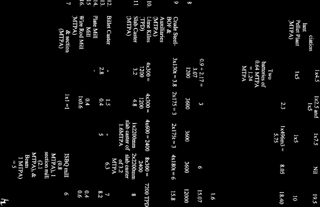
74
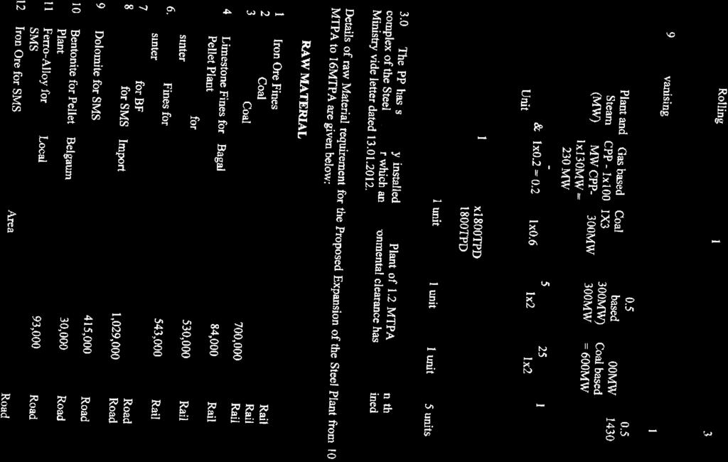
75

76
77
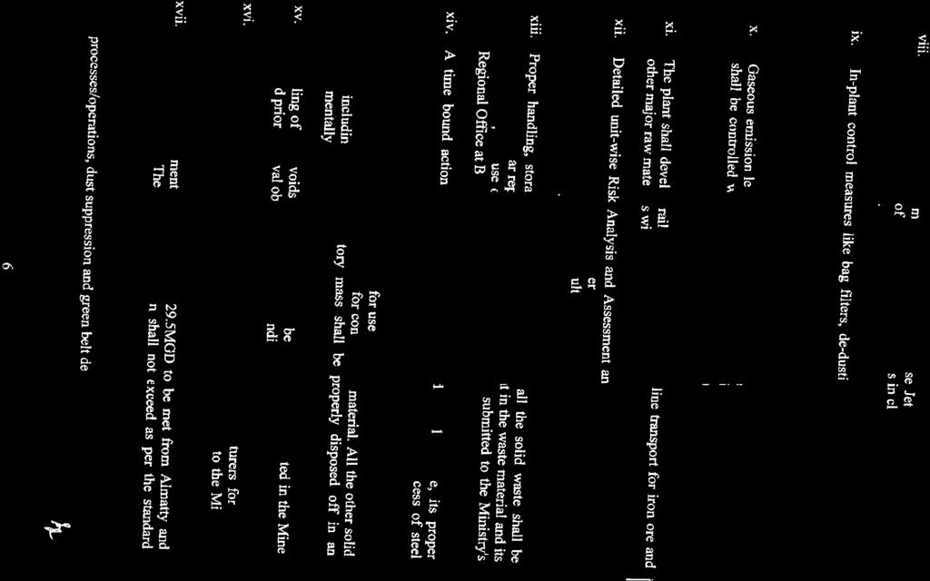
78

79

80
81
82

83
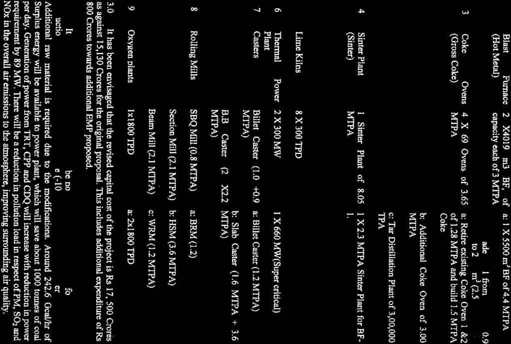
84

85

86

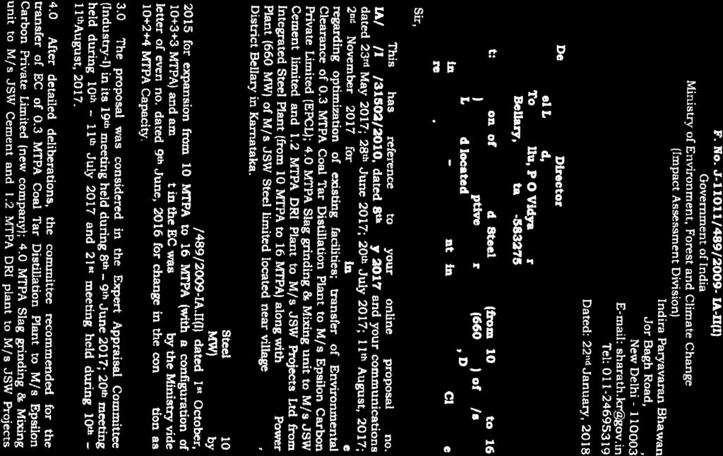
87
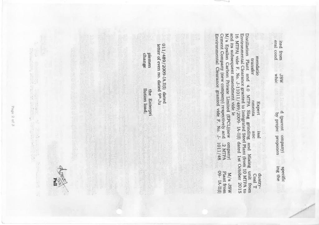

88
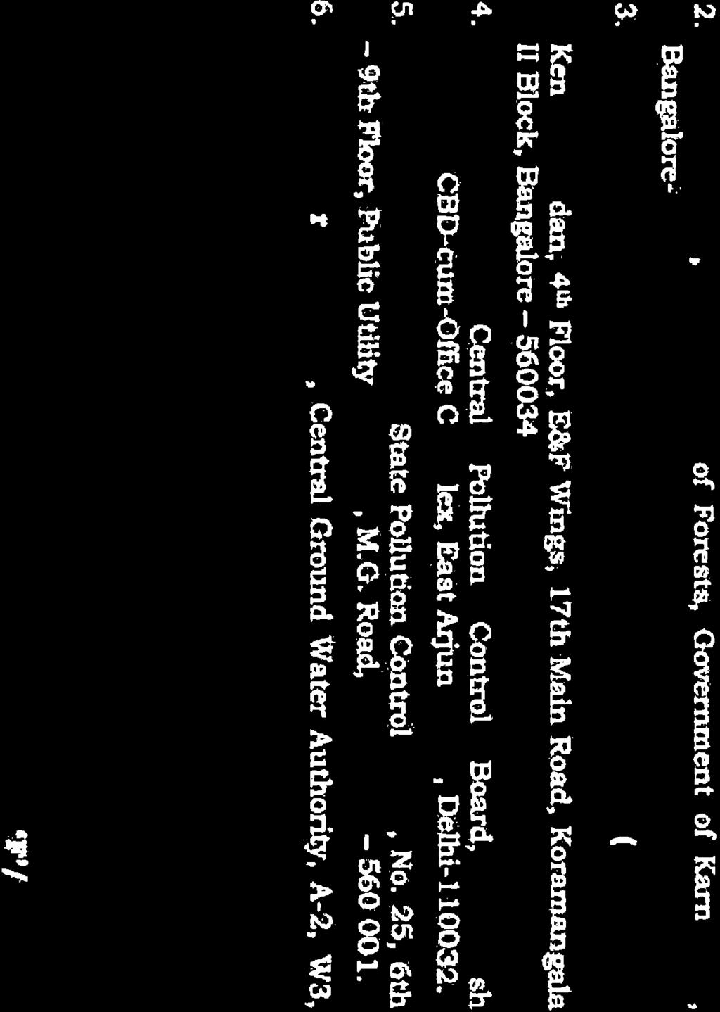
89
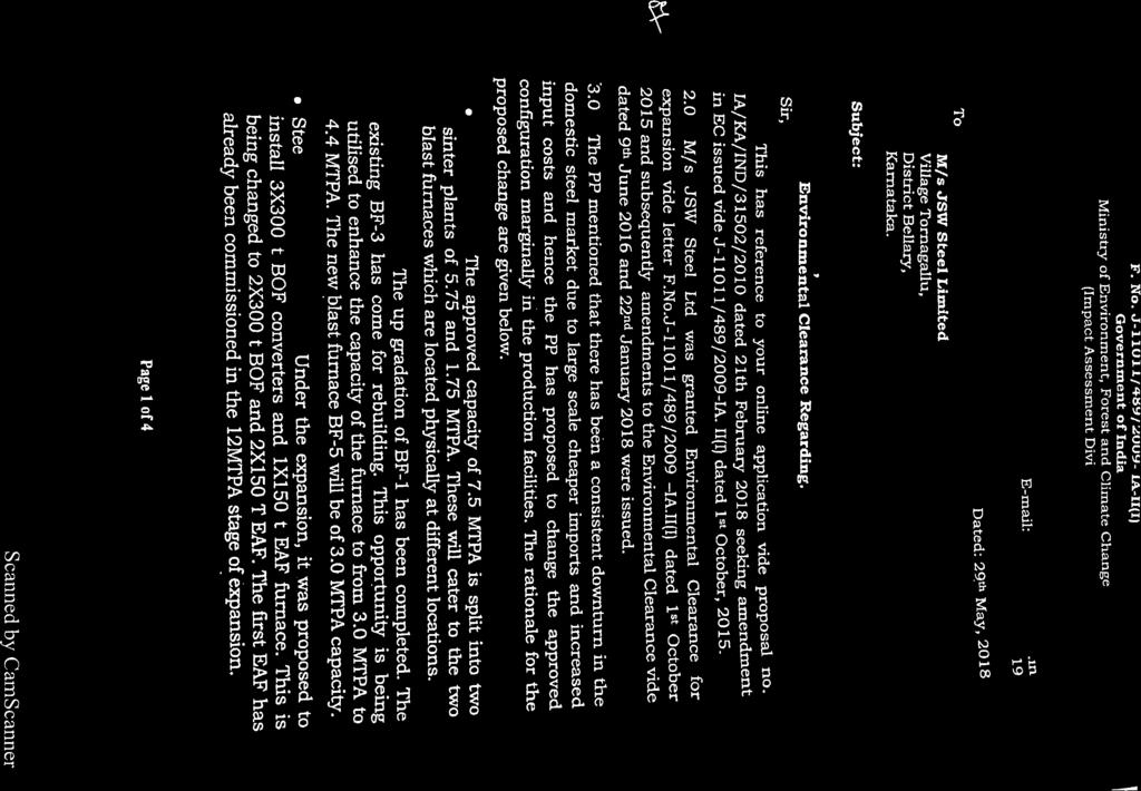
90
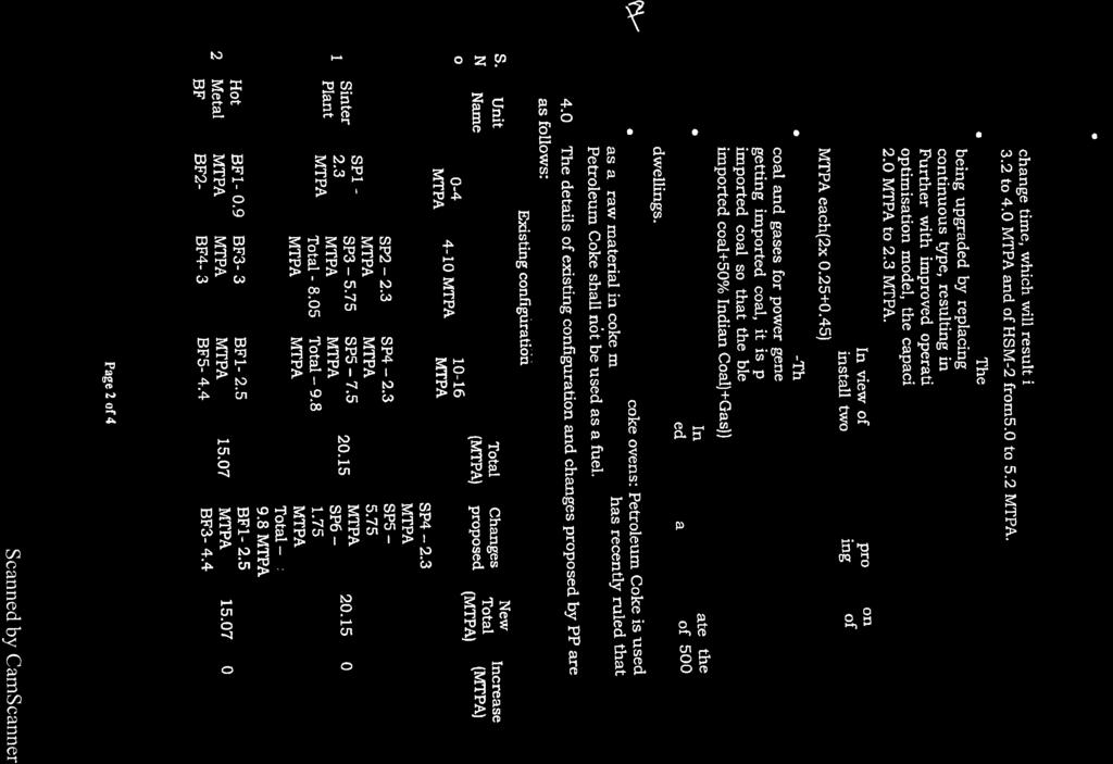
91


92
93