INVESTIGATION OF CARBURISATION METHODS FOR IMPROVED INTERNAL GEAR PERFORMANCE
|
|
|
- Marjory Cole
- 5 years ago
- Views:
Transcription
1 INVESTIGATION OF CARBURISATION METHODS FOR IMPROVED INTERNAL GEAR PERFORMANCE Lorinda Lakay A research report submitted to the Faculty of Engineering and the Built Environment, University of the Witwatersrand, Johannesburg, in partial fulfilment of the requirements for the degree of Masters of Science in Engineering. University of the Witwatersrand, Johannesburg, 2016
2 Declaration I declare that this dissertation is my own unaided work, other than where specifically acknowledged. It is being submitted in partial requirement for the degree of Masters of Science in Engineering (MSc 50/50) in the University of the Witwatersrand, Johannesburg. It has not been submitted before for any degree or examination in any other university. Signed this day of 20 Lorinda Lakay ii
3 Abstract With the current tough economic times and depressed commodity prices, focus is being placed on achieving higher power densities in gears without increased cost or reduced achievable life and reliability. An investigation into the use of different carburisation methods and processes to minimise post heat treatment distortion, with the aim to reduce and even eliminate the requirement for post heat treatment grinding and grinding stock allowances is presented. The investigation included the processing of test pieces, as per the recommendations of AGMA 2004-B89: Gear Materials, Heat Treatment and Processing Manual. Four alloy steels, namely AISI 3310, AISI 8620, AISI 9310 and 17CrNiMo6, were selected for this research, based on availability, cost and hardenability. The carburising cycles were derived for both gas and vacuum carburising for a 0.10% and 0.20% carbon steel respectively. Two quenching options were applied, oil quenching and intensive quenching. The test pieces were 3-dimensionally measured to determine distortion through the changes in diameter and ovality. The microstructures of the case and core were analysed, as well as effective case depth. This research found that current methods, atmospheric carburising and oil quenching, and steel alloy combinations are inadequate to produce low distortion carburised internal gears, while the use of vacuum carburising and intensive quenching as a process combination can achieve such gears. It was also found that the use of AISI 3310, performed the best for both current and proposed process combinations. It is recommended that future work be conducted, including a full-scaled manufacturing trial with more detailed process adjustments to ensure the quality and repeatability of the final carburised gear. iii
4 Acknowledgements I hereby acknowledge Joy Global, for their financial support, and Bedford Gear and Akron Steel Trading, for their assistance. I would like to extend my heartfelt thanks to Dr. Ronald Zab, Bedford Gear, and Mr. Ralph Poor, Surface Combustion, for their contribution and efforts in supporting me technically throughout this project. Thank you to Joseph Powell, Nikolai Kobasko and Bill Andreski for all the teleconferences on Intensive Quench. Thanks to my supervisors, Profs. L. Cornish and C. Polese for their guidance and patience. I also acknowledge my husband, Dr Wesley Doorsamy for all his support and motivation throughout my studies. iv
5 Contents List of Figures... viii List of Tables... xvi Chapter 1 Introduction General Research Objectives Report Overview... 3 Chapter 2 Background Fundamentals of Gearing Fundamentals of Steel Fundamentals of Gear Steels and Heat Treatment Gear Design and Rating Carburisation of Gears Quenching of Gears Distortion Chapter 3 Experimental Methodology Experimental Procedure Alloy Steels Test Pieces Identification of Test Pieces Dimensional Measurements of Test Pieces Carburising Cycles Reheat and Quench Temper Metallurgical and Distortion Analysis Chapter 4 Experimental Results Dimensional Measurements of Test Pieces v
6 4.1.1 Initial Measurements Measurements after Carburising Measurements after Quenching Metallurgical Analysis of Test Pieces Hardness Profile Conventional Gas Carburising and Oil Quench Conventional Gas Carburising and Intensive Quench Vacuum Carburising and Oil Quench Vacuum Carburising and Intensive Quench Microstructure Analysis Conventional Gas Carburising and Oil Quench Conventional Gas Carburising and Intensive Quench Vacuum Carburising and Oil Quench Vacuum Carburising and Intensive Quench Chapter 5 Discussion Microstructure Hardness Profile Distortion Alloy and Process Comparison Chapter 6 Conclusions General Conclusions Recommendations for Future Research Chapter 7 References Appendix A Microphotography A.1 Core Microstructure A.1.1 Conventional Gas Carburising and Oil Quench A.1.2 Conventional Gas Carburising and Intensive Quench vi
7 A.1.3 Vacuum Carburising and Oil Quench A.1.4 Vacuum Carburising and Intensive Quench A.2 Case Microstructure A.2.1 Conventional Gas Carburising and Oil Quench A.2.2 Conventional Gas Carburising and Intensive Quench A.2.3 Vacuum Carburising and Oil Quench A.2.4 Vacuum Carburising and Intensive Quench vii
8 List of Figures Figure 2.1: Main forms of gears- (a) external gear and (b) internal gear Figure 2.2: A planetary gear system Figure 2.3: Components of a planetary gear system Figure 2.4: Iron-carbon phase diagram for hypoeutectoid steels [13] Figure 2.5: Microstructure of austenite [9]... 9 Figure 2.6: Microstructure of ferrite [9] Figure 2.7: Microstructure of pearlite [9] Figure 2.8: Cooling rates and phase transformation in steels [14] Figure 2.9: Microstructure of martensite [9] Figure 2.10: Continuous-cooling transformation diagram for a eutectoid iron-carbon alloy [14] Figure 2.11: Effect of carbon contact on hardness [24] Figure 2.12: Total case depth as a function of carburising time and temperature [25] Figure 2.13: Boost-diffuse carburising cycle [18] Figure 2.14: Multiple boost-diffuse carburising cycle [26] Figure 2.15: Hardness gradient of a carburised steel [31] Figure 3.1: Experimental procedure of this work Figure 3.2: Low distortion carburising trial 3D cube Figure 3.3: Case hardenability [3] Figure 3.4: Test piece dimensions Figure 3.5: Test piece identification Figure 4.1: Hardness profile for AISI 8620 for gas carburising and oil quenching Figure 4.2: Hardness profile for AISI 3310 for gas carburising and oil quenching Figure 4.3: Hardness profile for 17CrNiMo6 for gas carburising and oil quenching Figure 4.4: Hardness profile for AISI 9310 for gas carburising and oil quenching Figure 4.5: Hardness profile for AISI 8620 for gas carburising and intensive quenching Figure 4.6: Hardness profile for AISI 3310 for gas carburising and intensive quenching Figure 4.7: Hardness profile for 17CrNiMo6 for gas carburising and intensive quenching Figure 4.8: Hardness profile for AISI 9310 for gas carburising and intensive quenching viii
9 Figure 4.9: Hardness profile for AISI 8620 for vacuum carburising and oil quenching Figure 4.10: Hardness profile for AISI 3310 for vacuum carburising and oil quenching Figure 4.11: Hardness profile for 17CrNiMo6 for vacuum carburising and oil quenching Figure 4.12: Hardness profile for AISI 9310 for vacuum carburising and oil quenching Figure 4.13: Hardness profile for AISI 8620 for vacuum carburising and intensive quenching Figure 4.14: Hardness profile for AISI 3310 for vacuum carburising and intensive quenching Figure 4.15: Hardness profile for 17CrNiMo6 for vacuum carburising and intensive quenching Figure 4.16: Hardness profile for AISI 9310 for vacuum carburising and intensive quenching Figure 5.1: Percentage change in ovality for AISI Figure 5.2: Percentage change in diameter for AISI Figure 5.3: Percentage change in ovality for AISI Figure 5.4: Percentage change in diameter for AISI Figure 5.5: Percentage change in ovality for 17CrNiMo Figure 5.6: Percentage change in diameter for 17CrNiMo Figure 5.7: Percentage change in ovality for AISI Figure 5.8: Percentage change in diameter for AISI Figure 5.9: Overall Steel Ratings Figure A.1: Tempered martensite and ferrite core microstructure for AISI 8620 for gas carburising and oil quench sample Figure A.2: Tempered martensite and ferrite core microstructure for AISI 8620 for gas carburising and oil quench sample Figure A.3: Tempered martensite and ferrite core microstructure for AISI 8620 for gas carburising and oil quench sample Figure A.4: Tempered martensite and ferrite core microstructure for AISI 3310 for gas carburising and oil quench sample Figure A.5: Tempered martensite and ferrite core microstructure for AISI 3310 for gas carburising and oil quench sample ix
10 Figure A.6: Tempered martensite and ferrite core microstructure for AISI 3310 for gas carburising and oil quench sample Figure A.7: Tempered martensite and ferrite core microstructure for 17CrNiMo6 for gas carburising and oil quench sample Figure A.8: Tempered martensite and ferrite core microstructure for 17CrNiMo6 for gas carburising and oil quench sample Figure A.9: Tempered martensite and ferrite core microstructure for 17CrNiMo6 for gas carburising and oil quench sample Figure A.10: Tempered martensite and ferrite core microstructure for AISI 9310 for gas carburising and oil quench sample Figure A.11: Tempered martensite and ferrite core microstructure for AISI 9310 for gas carburising and oil quench sample Figure A.12: Tempered martensite and ferrite core microstructure for AISI 9310 for gas carburising and oil quench sample Figure A.13: Tempered martensite and ferrite core microstructure for AISI 8620 for gas carburising and intensive quenching sample Figure A.14: Tempered martensite and ferrite core microstructure for AISI 8620 for gas carburising and intensive quenching sample Figure A.15: Tempered martensite and ferrite core microstructure for AISI 8620 for gas carburising and intensive quenching sample Figure A.16: Tempered martensite core microstructure for AISI 3310 for gas carburising and intensive quenching sample Figure A.17: Tempered martensite core microstructure for AISI 3310 for gas carburising and intensive quenching sample Figure A.18: Tempered martensite core microstructure for AISI 3310 for gas carburising and intensive quenching sample Figure A.19: Tempered martensite core microstructure for 17CrNiMo6 for gas carburising and intensive quenching sample Figure A.20: Tempered martensite core microstructure for 17CrNiMo6 for gas carburising and intensive quenching sample Figure A.21: Tempered martensite core microstructure for 17CrNiMo6 for gas carburising and intensive quenching sample x
11 Figure A.22: Tempered martensite with minimal ferrite core microstructure for AISI 9310 for gas carburising and intensive quenching sample Figure A.23: Tempered martensite with minimal ferrite core microstructure for AISI 9310 for gas carburising and intensive quenching sample Figure A.24: Tempered martensite with minimal ferrite core microstructure for AISI 9310 for gas carburising and intensive quenching sample Figure A.25: Tempered martensite with ferrite core microstructure for AISI 8620 for vacuum carburising and oil quenching sample Figure A.26: Tempered martensite with ferrite core microstructure for AISI 8620 for vacuum carburising and oil quenching sample Figure A.27: Tempered martensite with ferrite core microstructure for AISI 8620 for vacuum carburising and oil quenching sample Figure A.28: Tempered martensite with ferrite core microstructure for AISI 3310 for vacuum carburising and oil quenching sample Figure A.29: Tempered martensite with ferrite core microstructure for AISI 3310 for vacuum carburising and oil quenching sample Figure A.30: Tempered martensite with ferrite core microstructure for AISI 3310 for vacuum carburising and oil quenching sample Figure A.31: Tempered martensite with ferrite core microstructure for 17CrNiMo6 for vacuum carburising and oil quenching sample Figure A.32: Tempered martensite with ferrite core microstructure for 17CrNiMo6 for vacuum carburising and oil quenching sample Figure A.33: Tempered martensite with ferrite core microstructure for 17CrNiMo6 for vacuum carburising and oil quenching sample Figure A.34: Tempered martensite with ferrite core microstructure for AISI 9310 for vacuum carburising and oil quenching sample Figure A.35: Tempered martensite with ferrite core microstructure for AISI 9310 for vacuum carburising and oil quenching sample Figure A.36: Core Tempered martensite with ferrite core microstructure for AISI 9310 for vacuum carburising and oil quenching sample Figure A.37: Tempered martensite with ferrite core microstructure for AISI 8620 for vacuum carburising and intensive quenching sample xi
12 Figure A.38: Tempered martensite with ferrite core microstructure for AISI 8620 for vacuum carburising and intensive quenching sample Figure A.39: Tempered martensite with ferrite core microstructure for AISI 8620 for vacuum carburising and intensive quenching sample Figure A.40: Tempered martensite core microstructure for AISI 3310 for vacuum carburising and intensive quenching sample Figure A.41: Tempered martensite core microstructure for AISI 3310 for vacuum carburising and intensive quenching sample Figure A.42: Tempered martensite core microstructure for 17CrNiMo6 for vacuum carburising and intensive quenching sample Figure A.43: Tempered martensite core microstructure for 17CrNiMo6 for vacuum carburising and intensive quenching sample Figure A.44: Tempered martensite core microstructure for 17CrNiMo6 for vacuum carburising and intensive quenching sample Figure A.45: Tempered martensite with minimal ferrite core microstructure for AISI 9310 for vacuum carburising and intensive quenching sample Figure A.46: Tempered martensite with minimal ferrite core microstructure for AISI 9310 for vacuum carburising and intensive quenching sample Figure A.47: Martensite case microstructure for AISI 8620 for gas carburising and oil quenching sample Figure A.48: Martensite case microstructure for AISI 8620 for gas carburising and oil quenching sample Figure A.49: Martensite case microstructure for AISI 8620 for gas carburising and oil quenching sample Figure A.50: Martensite case microstructure for AISI 3310 for gas carburising and oil quenching sample Figure A.51: Martensite case microstructure for AISI 3310 for gas carburising and oil quenching sample Figure A.52: Martensite case microstructure for AISI 3310 for gas carburising and oil quenching sample Figure A.53: Martensite case microstructure for 17CrNiMo6 for gas carburising and oil quenching sample xii
13 Figure A.54: Martensite case microstructure for 17CrNiMo6 for gas carburising and oil quenching sample Figure A.55: Martensite case microstructure for 17CrNiMo6 for gas carburising and oil quenching sample Figure A.56: Martensite case microstructure for AISI 9310 for gas carburising and oil quenching sample Figure A.57: Martensite case microstructure for AISI 9310 for gas carburising and oil quenching sample Figure A.58: Martensite case microstructure for AISI 9310 for gas carburising and oil quenching sample Figure A.59: Martensite case microstructure for AISI 8620 for gas carburising and intensive quenching sample Figure A.60: Martensite case microstructure for AISI 8620 for gas carburising and intensive quenching sample Figure A.61: Martensite case microstructure for AISI 8620 for gas carburising and intensive quenching sample Figure A.62: Martensite case microstructure for AISI 3310 for gas carburising and intensive quenching sample Figure A.63: Martensite case microstructure for AISI 3310 for gas carburising and intensive quenching sample Figure A.64: Martensite case microstructure for AISI 3310 for gas carburising and intensive quenching sample Figure A.65: Martensite case microstructure for 17CrNiMo6 for gas carburising and intensive quenching sample Figure A.66: Martensite case microstructure for 17CrNiMo6 for gas carburising and intensive quenching sample Figure A.67: Martensite case microstructure for 17CrNiMo6 for gas carburising and intensive quenching sample Figure A.68: Martensite case microstructure for AISI 9310 for gas carburising and intensive quenching sample Figure A.69: Martensite case microstructure for AISI 9310 for gas carburising and intensive quenching sample xiii
14 Figure A.70: Martensite case microstructure for AISI 9310 for gas carburising and intensive quenching sample Figure A.71: Martensite case microstructure for AISI 8620 for vacuum carburising and oil quenching sample Figure A.72: Martensite case microstructure for AISI 8620 for vacuum carburising and oil quenching sample Figure A.73: Martensite case microstructure for AISI 8620 for vacuum carburising and oil quenching sample Figure A.74: Martensite case microstructure for AISI 3310 for vacuum carburising and oil quenching sample Figure A.75: Martensite case microstructure for AISI 3310 for vacuum carburising and oil quenching sample Figure A.76: Martensite case microstructure for AISI 3310 for vacuum carburising and oil quenching sample Figure A.77: Martensite case microstructure for 17CrNiMo6 for vacuum carburising and oil quenching sample Figure A.78: Martensite case microstructure for 17CrNiMo6 for vacuum carburising and oil quenching sample Figure A.79: Martensite case microstructure for 17CrNiMo6 for vacuum carburising and oil quenching sample Figure A.80: Martensite case microstructure for AISI 9310 for vacuum carburising and oil quenching sample Figure A.81: Martensite case microstructure for AISI 9310 for vacuum carburising and oil quenching sample Figure A.82: Martensite case microstructure for AISI 9310 for vacuum carburising and oil quenching sample Figure A.83: Martensite case microstructure for AISI 8620 for vacuum carburising and intensive quenching sample Figure A.84: Martensite case microstructure for AISI 8620 for vacuum carburising and intensive quenching sample Figure A.85: Martensite case microstructure for AISI 8620 for vacuum carburising and intensive quenching sample xiv
15 Figure A.86: Martensite case microstructure for AISI 3310 for vacuum carburising and intensive quenching sample Figure A.87: Martensite case microstructure for AISI 3310 for vacuum carburising and intensive quenching sample Figure A.88: Martensite case microstructure for 17CrNiMo6 for vacuum carburising and intensive quenching sample Figure A.89: Martensite case microstructure for 17CrNiMo6 for vacuum carburising and intensive quenching sample Figure A.90: Martensite case microstructure for 17CrNiMo6 for vacuum carburising and intensive quenching sample Figure A.91: Martensite case microstructure for AISI 9310 for vacuum carburising and intensive quenching sample Figure A.92: Martensite case microstructure for AISI 9310 for vacuum carburising and intensive quenching sample xv
16 List of Tables Table 2.1: Compositions of common carburising steels (wt%) [10] Table 2.2: AGMA allowable stresses [4] Table 3.1: Experimental inputs Table 3.2: Low distortion carburising trial matrix Table 3.3: AGMA test piece sizes [3] Table 3.5: Test piece material identification code Table 3.6: Carburising and quenching method test piece designations Table 3.7: Gas carburising boost-diffuse cycles Table 3.8: Vacuum carburising boost-diffuse cycles Table 4.1: Initial measurements for AISI Table 4.2: Initial measurements for AISI Table 4.3: Initial measurements for 17CrNiMo Table 4.4: Initial measurements for AISI Table 4.5: Measurements after carburising for AISI Table 4.6: Measurements after carburising for AISI Table 4.7: Measurements after carburising for 17CrNiMo Table 4.8: Measurements after carburising for AISI Table 4.9: Measurements after quenching for AISI Table 4.10: Measurements after quenching for AISI Table 4.11: Measurements after quenching for 17CrNiMo Table 4.12: Measurements after quenching for AISI Table 4.13: Case and core microstructures for AISI Table 4.14: Case and core microstructures for AISI Table 4.15: Case and core microstructures for 17CrNiMo Table 4.16: Case and core microstructures for AISI Table 4.17: Case and core microstructures for AISI Table 4.18: Case and core microstructures for AISI Table 4.19: Case and core microstructures for 17CrNiMo Table 4.20: Case and core microstructures for AISI xvi
17 Table 4.21: Case and core microstructures for AISI Table 4.22: Case and core microstructures for AISI Table 4.23: Case and core microstructures for 17CrNiMo Table 4.24: Case and core microstructures for AISI Table 4.25: Case and core microstructures for AISI Table 4.26: Case and core microstructures for AISI Table 4.27: Case and core microstructures for 17CrNiMo Table 4.28: Case and core microstructures for AISI Table 5.1: Hardness Parameters for AISI Table 5.2: Hardness Parameters for AISI Table 5.3: Hardness Parameters for 17CrNiMo Table 5.4: Hardness Parameters for AISI Table 5.5: Measured Distortion for AISI Table 5.6: Measured distortion for AISI Table 5.7: Measured distortion for 17CrNiMo Table 5.8: Measured distortion for AISI Table 5.9: Alloy and process rating xvii
18 Chapter 1 Introduction 1.1 General Gearing is one the most common means of industrial power transmission, and is used in a wide range of industries such as mining, oil and gas, and minerals processing [1]. With the current tough economic times and depressed commodity prices, focus is being placed on achieving higher power densities without increased cost or reduced achievable life and reliability [2]. To be able to achieve this, improved design and manufacturing processes are required. These processes include the hardening of the gear teeth to improve strength and wear. Wear on gears is generally ovehrcome through the heat treatment of the gear teeth to make the surfaces more wear resistant. However, there are limitations of current heat treatment processes, particularly carburisation, which can affect the usability of these processes on certain gears, particularly internal gears [3]. One such limitation is the resultant distortion during carburisation. To date, there has been much research in the field of carburisation of external gears, with little focus on internal gears. Unlike external gears, internal gears are thin in section, resembling a ring. Hence, internal gears are also known as ring gears. The use of internal gears is limited to planetary gear systems, which are not as common as external gear drive trains. Most planetary gear systems are used in low to moderate power applications, where large reductions in speed are necessary. However, some applications, such as heavy industrial equipment, do require the use of planetary gear systems for the increase in torque. In these instances, planetary gear systems are utilised for their compact nature. The power density of the gearing system is the key criterion in these applications. Most internal gears, used in these planetary systems, utilise induction hardening to improve hardness and wear resistance of the gears during operation. While induction hardening provides a low distortion option for heat treating gears, it also means a compromise in mechanical properties, since it does not promote as high hardness as carburising [4]. Furthermore, conventional gas carburising processes are prone to unpredictable and uncontrollable distortion when used on internal gears. 1
19 This research will form the basis to develop an industrial process that will enable the cost effective manufacture of a carburised internal gear which requires little or no machining and grinding after heat treatment, on a mass scale, for use on heavy mining equipment. It will investigate the use of traditional and novel carburising methods and processes, as well as explore the benefits of various steel specifications to determine the best fit pairing of carburising and quenching combinations for reduced distortion in an industrial application. 1.2 Research Objectives The research will investigate the use of different carburisation methods and processes to minimise post heat treatment distortion, with the aim to reduce and even eliminate the requirement for post heat treatment grinding and grinding stock allowances, ultimately to mitigate the increase in manufacturing costs normally associated with the increase in hardness. The primary aims of the research are as follows: To compare gas and vacuum carburising methods for distortion. To compare oil quenching to intensive quenching for distortion. To determine which carburising grade alloy steel would be most viable for further technology development. To determine the best carburising-quenching and alloy steel combinations that warrant further development towards a production prototype. 2
20 1.3 Report Overview This document is arranged as follows: Chapter 2: Background An overview of previous research relevant to low distortion carburisation is presented. Chapter 3: Experimental Methodology The experimental methodology and procedures utilised in the research are detailed. Chapter 4: Experimental Results The achieved data are analysed and the results are presented. Chapter 5: Discussion The experimental results and the implications thereof are discussed. Chapter 6: Conclusions The conclusions of the research are presented and recommendations are provided. 3
![Chapter 2 Background 2.1 Fundamentals of Gearing Gears are one of the oldest and most common mechanisms used in machinery and mechanical systems, such as clocks, bicycles and industrial equipment [1].](/docs-images/89/99935842/images/21-0.jpg "Gears are a cost effective, relatively efficient and reliable means to either increase or decrease torque and speed, as required.")
, while an internal gear is one where the gear teeth are situated radially inward, i.e. facing the axis of rotation, as shown in Figure 2.1(b).")
21 Chapter 2 Background 2.1 Fundamentals of Gearing Gears are one of the oldest and most common mechanisms used in machinery and mechanical systems, such as clocks, bicycles and industrial equipment [1]. Gears are a cost effective, relatively efficient and reliable means to either increase or decrease torque and speed, as required. In its simplest form, there exists two main types of gears: external and internal. An external gear is one where the gear teeth are situated radially outwards, i.e. the teeth are pointed away from the axis of rotation of the gear, as shown in Figure 2.1(a), while an internal gear is one where the gear teeth are situated radially inward, i.e. facing the axis of rotation, as shown in Figure 2.1(b). This research is focussed on the heat treatment of internal gears, which are particularly prone to distortion, thus requiring costly post-heat treatment machining. (a) (b) Figure 2.1: Main forms of gears- (a) external gear and (b) internal gear. The primary application of an internal gear is to enable the configuration of gears in an epicyclic or planetary gear system [5], as shown in Figure

22 Figure 2.2: A planetary gear system. A planetary gear system is a gear train which consists of an internal gear and multiple external gears. A planetary gear system, also known as an epicyclic gear system, has several components: a sun, planets, carriers and ring gear, as shown in Figure 2.3. The sun gear is an external gear whose axis of rotation is located at the centre of the entire system, much in the same way as earth s sun is the centre of rotation for the solar system. The planet gears are also external gears which rotate about the sun gear, and are in essence, idler gears, meshing with both the sun and ring gears. There are multiple planet gears in a planetary gear system, generally ranging from three to six gears, with some planetary systems having as many as eight planet gears, depending on the size and application of the planetary system. The planet gears, like planets in the solar system, also rotate about their own centre of rotation while rotating around the sun gear. The planets rotate about shafts which are supported by the planet carrier. The resultant centre of rotation of the carrier and the sun gear coincides with centre of the ring gear. The ring gear is the internal gear of the planetary gear system. This coincidence of the axes of rotation gives the planetary gear system its compact nature. The ring gear forms the boundary of the gear system, with the entire gear system being enclosed within the ring gear. 5
![Figure 2.3: Components of a planetary gear system. The following are the main advantages of planetary gear systems [6]: 1.](/docs-images/89/99935842/images/23-0.jpg "Planetary gear systems are more compact for a given ratio than traditional spur gear drives. 2. Planetary gear systems have excellent efficiency, with a typical power loss of 3% per stage.")
23 Figure 2.3: Components of a planetary gear system. The following are the main advantages of planetary gear systems [6]: 1. Planetary gear systems are more compact for a given ratio than traditional spur gear drives. 2. Planetary gear systems have excellent efficiency, with a typical power loss of 3% per stage. This makes planetary gear systems a power efficient alternative to spur gear drives. 3. Planetary gear systems have a distributed load. This is due to the multiple planet gears sharing the torque, resulting in a greater torque capability. While planetary gear systems boast many advantages over parallel shaft spur gear drives, they also have disadvantages, which include: 1. Planetary gear systems are complex to design and may require specialist knowledge [7]. 2. Planetary gear systems are costly to manufacture; the gears require a tight tolerance because the backlash of the planetary gears cannot be adjusted once assembled. 3. Planetary gear systems are difficult to assemble. The reliability of planetary gear systems depend heavily on accurate machining to ovehrcome some of these difficulties. 6
24 4. Planetary gear systems have much higher dynamic gear loads than static loads. This results in shorter fatigue lives of components [8]. 5. Planetary gear systems are susceptible to high rates of wear due to the gears having multiple simultaneous contacts. If a planetary gear system has 4 planetary gears, the sun and ring gears have four times the contacts of external gear drive, resulting in a shorter contact fatigue life. 2.2 Fundamentals of Steel Since most industrial gears are manufactured from steel, it is important that the fundamentals of steel be understood. In the following section, the fundamentals of steel composition, microstructure and phase transformation will be explored. Steel in its most simple form is a solution of carbon in iron. However, the steels used for gearing are generally considered low in its carbon concentration, with less than 0.8wt% carbon, while steels for carburising generally contain less than 0.25 wt% carbon. These steels are known as hypoeutectoid steels [9]. It should also be noted that the steels used for industrial gearing also contain other elements, such as manganese, chromium and nickel. These alloying constituents are used to enhance certain properties in the steel [9]. The primary effects are as follows: Manganese increases the hardenability of the steel. It is used to increase the strength and hardness. It can produce an austenitic steel, when used in sufficient quantities. Chromium also increases the hardenability of the steel, as well as increase the strength and hardness. It is also used to counteract the disadvantage of nickel which is susceptibility to oxidisation along grain boundaries caused by nickel not uniting with carbon. Nickel increases the hardenability and fatigue resistance of the steel. It strengthens the steel and improves toughness. It is also used to counteract the disadvantages of chromium which are a higher critical temperature and decrease impact resistance. With the topic of this research being focussed on carburisation, the composition of some common carburising steels are shown in Table 2.1 [10]. 7
25 Table 2.1: Compositions of common carburising steels (wt%) [10]. Alloying Element [wt%] AISI 3310 AISI 4320 AISI 8620 AISI 9310 Carbon (C) Manganese (Mn) Nickel (Ni) Chromium (Cr) Molybdenum (Mo) none To further understand steels, the various microstructures and phase transformations of heat treated steels need to be explored. When heat treated, steels undergo phase changes, and the microstructure of the steel changes. Time and temperature are of critical importance in the heat treatment of steels. These two parameters determine the microstructure and mechanical properties of the steel, such as ductility, hardness, strength and toughness [9]. The relationship between temperature and microstructure is shown in the equilibrium phase diagram [11]. The phase diagram represents the phase transformations and microstructures in slowly cooled steels, under equilibrium conditions. Departure from these conditions, i.e. rapid cooling, results in changes in these microstructures [12]. The composition for hypoeutectoid steel is shown on the phase diagram in Figure 2.4 [13]. 8
![Figure 2.4: Iron-carbon phase diagram for hypoeutectoid steels [13].](/docs-images/89/99935842/images/26-0.jpg "The phases for steel are: Austenite is the solid non-magnetic phase where carbon and other constituents form a")

26 Figure 2.4: Iron-carbon phase diagram for hypoeutectoid steels [13]. The phases for steel are: Austenite is the solid non-magnetic phase where carbon and other constituents form a solution of γ-iron, hence it is designated by γ. It is the desired microstructure prior to hardening and is stable at high temperatures. It is a face-cubic centered (fcc) structure. Austenite is shown Figure 2.5 [9]. Figure 2.5: Microstructure of austenite [9]. 9

27 Ferrite is a body-cubic centered (bcc) structure that normally occurs at room temperature in low carbon steels. It is designated by α. Ferrite experiences a polymorphic transformation to austenite at approximately 912 C. Ferrite is relatively soft with a very low carbon solubility. Ferrite is shown Figure 2.6 [9]. Figure 2.6: Microstructure of ferrite [9]. Cementite is a compound of iron and carbon, iron carbide (Fe3C), which is very hard and brittle. In alloy steels, some of the iron atoms are replaced by other alloying elements, e.g. chromium and manganese. Pearlite forms when austenite is slow cooled from the eutectoid temperature reaction γ α + Fe3C and forms lamellae (layers) of ferrite and cementite. The thickness ratio of these layers of ferrite and cementite in pearlite is usually 8:1, depending on the temperature at which the transformation occurs. If the thickness is greater, a coarse pearlite has formed, while if the thickness is less, a fine pearlite has formed. Pearlite is shown Figure 2.7 [9]. 10
![Figure 2.7: Microstructure of pearlite [9]. Martensite is formed when austenite is rapidly cooled, i.e. quenched, when the cooling rate is rapid enough to prevent diffusion of the carbon, which normally forms cementite in pearlite, as shown in Figure 2.](/docs-images/89/99935842/images/28-0.jpg "8 [14]. To obtain martensite in a plain carbon steel, a very rapid cooling rate is needed. It is better to use a slower cooling rate, so to allow this, other alloying elements are added (e.g. chromium) which slows down the martensite transformation.")
28 Figure 2.7: Microstructure of pearlite [9]. Martensite is formed when austenite is rapidly cooled, i.e. quenched, when the cooling rate is rapid enough to prevent diffusion of the carbon, which normally forms cementite in pearlite, as shown in Figure 2.8 [14]. To obtain martensite in a plain carbon steel, a very rapid cooling rate is needed. It is better to use a slower cooling rate, so to allow this, other alloying elements are added (e.g. chromium) which slows down the martensite transformation. Figure 2.8: Cooling rates and phase transformation in steels [14]. Since it is formed through quenching, a non-equilibrium process, martensite does not appear on the iron-carbon phase diagram. A martensitic structure is shown in Figure 2.9 [9]. 11
![Figure 2.9: Microstructure of martensite [9]. Martensite is the preferred structure for gears after heat treatment, but is usually tempered to release some of the strain.](/docs-images/89/99935842/images/29-0.jpg "Tempering is the heating of the steel to a temperature below the transformation temperature to increase strength and toughness of the steel.")
29 Figure 2.9: Microstructure of martensite [9]. Martensite is the preferred structure for gears after heat treatment, but is usually tempered to release some of the strain. Tempering is the heating of the steel to a temperature below the transformation temperature to increase strength and toughness of the steel. Martensite has a body-centered tetragonal (bct) structure, which results in a volumetric increase, because bct is not a close-packed structure compared to austenite [9]. The transformation of austenite into pearlite and martensite is dependent on the rate of cooling and the transformation temperature for a particular steel composition, with martensite formed through rapid cooling. These transformations are shown on continuous-cooling transformation (CCT) diagrams which are for a specific composition. The CCT diagram for a eutectoid steel is shown in Figure 2.10 [14]. 12
30 Figure 2.10: Continuous-cooling transformation diagram for a eutectoid iron-carbon alloy [14]. 2.3 Fundamentals of Gear Steels and Heat Treatment Alloy steels are the preferred material for industrial gears, due to their higher hardenability. These steels also have the desired microstructure of the hardened case and core required for high fatigue strength [21]. Some of the alloy steels that offer acceptable heat treated properties include AISI 4140 (EN19/ 708M40) and AISI 4340 (EN24/ 817M40) [3]. Heat treatment optimises the performance and extends the life of gears by altering the chemical, metallurgical and physical properties, i.e. the microstructure of the steel. Heat treatment allows for easier machining of the gear alloy in its softer state, and operation of the gear in a harder, higher strength state. The harder state provides wear and fatigue resistance. The selection of the steel is dependent on the required mechanical and physical properties of the heat treated steel, which are in turn determined by the operating conditions of the gears [15]. Thus, a critical part of gear design is the understanding of the importance and complexity of the heat treatment of gears. There are multiple heat treatment processes used on gears [16]. These heat treatment processes include: 13
31 Through-hardening Induction Hardening Nitriding and Carbonitriding Carburising. However, these heat treatment process are not suitable to all applications and need to be selected based on criteria for manufacture and operation [17]. Gears generally require tight profile tolerances, in the range of a 2-12 µm, to efficiently transmit torque or motion. If the tolerance on the gear is too large, it can greatly alter the contact geometry of the gear, resulting in reduced load-carrying capacity and increased wear on the gear flanks, leading to catastrophic failure of the gear teeth. This is particularly valid for planetary gear systems where the assembly does not allow for post-manufacture adjustments. Therefore, the ability to control, predict and eliminate undesirable distortion during heat treatment is a dominant factor when selecting a heat treatment process [15]. The reduction of distortion in gears requires post heat treatment machining processes, hence the elimination and control of distortion can reduce the cost and improve the performance of the gears [17]. This resultant distortion is discussed in further detail in Section 2.7. Traditionally, on applications where distortion control is critical, such as internal gears, induction hardening is considered the safest heat treatment process [19]. In comparison to carburising, induction hardening does not require the heating of the entire part, and can be localised to the area on the gear requiring the improved properties that the heat treatment provides [15]. Therefore, the likelihood and severity of any distortion is minimised. However, induction hardening, because of the use of probes, is preferred for use on large gears. It is not easily controllable on fine-pitched gears [20], due to its tendancy to through harden tooth landings, creating brittle zones. The materials suitable to induction hardening on gears are medium to high alloy steels [15]. While performance is a critical consideration, another important consideration is the cost of the steel and cost to machine the selected steel into a usable gear. To meet these cost implications, low to medium-alloy steels are generally used in conjunction with heat treatment processes which improve the mechanical properties of the steel. The required steel is generally selected based on the accompanying heat treatment process. 14
32 2.4 Gear Design and Rating There are many standards: ISO, DIN, AGMA; which provide design procedures and calculations for gears. Considering the fundamentals of gears, the strength of gears is calculated using the Lewis formula [22]: (2.1) where W = allowable transmittable load [N]. S = allowable stress for the gear material [MPa]. K = velocity factor. F = width of the face of the gear [mm]. Y = form factor for the gear dependent on the number of teeth and the pressure angle. P = diametral pitch of the gear [mm]. From Equation 2.1, the allowable load for a gear is proportional to the allowable stress of the material. Thus, when considering the selection of the heat treatment process of gears, the required load rating is a large factor. Considering the design standards of the American Gear Manufacturer s Association (AGMA), the allowable stress in a gear tooth is dependent on the achievable hardness of the gear tooth after heat treatment [4] (Table 2.2). This standard specifies the minimum case hardness of induction hardened and carburised gear teeth as 50HRC (Rockwell Hardness, C scale) and 58HRC, respectively, for AGMA Grade 2 and 3 materials, with a maximum case hardness 55HRC and 62HRC, respectively. The standard also recommends a core hardness range of 35-45HRC for carburising and 30-37HRC for induction hardening. The AGMA material grade is a measure of steel cleanliness and the quality controls attached to that steel, with Grade 3 being a very clean steel with tight quality controls. 15
33 Table 2.2: AGMA allowable stresses [4]. Heat Treatment Allowable Bending Stress [MPa] Allowable Contact Stress [MPa] Grade 2 Grade 3 Grade 2 Grade 3 Induction Hardening 380 N/A 1310 N/A Carburising Table 2.2 shows that with the use of a carburised steel, an 18% increase in the allowable stresses for both bending and contact can be achieved compared to induction hardening. Hence, for the high power density required for industrial gearing, the use of carburised gearing is more beneficial than induction hardened gearing. 2.5 Carburisation of Gears By far the highest strength gears are achieved through carburisation, as shown in Table 2.2. Carburisation is a process where a ferrous metal is diffused with carbon to create a carbon gradient which is high at the surface and low at the core [18]. This allows for a hard outer shell, known as a case, and a softer, tougher core, which is beneficial to gears [23]. The maximum hardness of the steel is dependent on the carbon content in the steel, as shown in Figure 2.11 [24]. Figure 2.11: Effect of carbon contact on hardness [24]. 16
34 Gears are generally carburised using a gaseous medium, which generates a carbonaceous atmosphere within the heat treatment furnace. The amount of carbon diffused into the gear is a function of the time and temperature of the gear in the furnace [25], as shown in Figure Figure 2.12: Total case depth as a function of carburising time and temperature [25]. There are two main methods of carburising which are utilised today: conventional gas and low pressure or vacuum carburising. While conventional gas carburising, commonly known as atmospheric carburising, takes place at close to atmospheric pressures, vacuum carburising (as its name suggests) is carried out at low pressures approaching a vacuum [26]. Vacuum carburising boasts the advantage of eliminating the creation of oxides on the surface of the parts being carburised, as well as having higher furnace temperatures, and thus, shorter cycle times. Both carburising methods utilise a two-stage process known as a boost-diffuse cycle, shown in Figure 2.13 [18], whereby carbon at higher concentrations than the final surface content is utilised to increase the carbon diffusion into the steel, after which the carbon concentration is lowered to the final surface content. 17
35 Figure 2.13: Boost-diffuse carburising cycle [18]. Vacuum carburising may also utilise a variation of the boost-diffuse cycle, where by multiple boost diffuse cycles are used, as shown in Figure 2.14 [26]. Figure 2.14: Multiple boost-diffuse carburising cycle [26]. 18
36 Once the required amount of carbon is diffused into the gear, through either carburisation method, the gear is quenched to achieve the required case depth and microstructure. The microstructure for a carburised case is normally a mixture of tempered martensite and retained austenite, while other phase combinations such as pearlite are generally avoided [29]. The case depth of a carburised gear is defined as the distance from the surface (where there is higher carbon) to where the carbon content equals that of the initial carbon content of the core, i.e. for AISI 4320 steel the carbon content reaches 0.20%. The targeted effective case depth for any carburised steel is defined as the distance at which a hardness of 50HRC is measured [30]. The case depth of a gear is measured using hardness testers to achieve a hardness gradient, which is determined according to DIN 50190, Part 1, where the measured hardness is plotted against the distance, as shown in Figure 2.15 [31]. Figure 2.15: Hardness gradient of a carburised steel [31]. 19
37 2.6 Quenching of Gears Quenching is the rapid cooling of a material which aims to inhibit phase transformations on cooling and harden the material [25]. Depending on the required properties, parts can be quenched in oil or water, although for gears, oil is the most common quenching fluid due to the alloy compositions. Fine pitched gears may require more aggressive quenching rates. Traditionally, most gears are directly quenched in oil, which means that the gears are quenched directly from the furnace. Alternatively, some gears, especially those manufactured from highalloy steels, may be cooled to room/air temperature, then reheated to the austenitic temperature region and quenched to reduce distortion [25]. The carburised-cooled-reheat procedure is also used when there are surfaces on the component that do not require a case, but still require hardening. This is achieved by machining away the case in these areas prior to reheating and quenching. The reheat and quench process may also be used in cases where parts are individually quenched because of the need for fixturing [25], i.e. the use of jigs and fixtures to enable handling of the parts. Another quenching method is the Intensive Quench [27], which was developed by Kobasko in the 1960s. Intensive Quench, or IQ, provides an alternative to conventional oil quenching. IQ has extremely high cooling rates. This interrupted quenching process utilises highly agitated water as a quenching medium, and produces less distortion in thin section parts due to faster, more uniformed cooling [27]. This would be beneficial in the carburisation of internal gears, which are thin sectioned. For a modern gear manufacturing plant, IQ has the following additional benefits: 1. The use of water as the quenching medium is more environmentally friendly than oil. It also eliminates one of the largest risks in a plant, burning oil. 2. With higher cooling rates, the time to quench a part is reduced, resulting in a shorter heat treatment time. The predictable distortion also allows for further reductions in the post-heat treatment machining, creating more time savings. These time savings equate to lower manufacturing costs per part and higher productivity for the plant. 20
38 2.7 Distortion Distortion is always a problem in heat treatment, but is most severe in carburising. There are two types of distortion for gears [18]: Body distortion which is distortion in the body surrounding the gear teeth, and is measured in terms of out-of-roundness (ovality), out-of-flatness (straightness) and runout, which is the deviation of cylindrical shape from the true centre. Tooth distortion which is distortion in the gear geometry, and is influenced by the body distortion. Previously, carburised and ground gears required excessive finishing processes, resulting in high manufacturing costs and poor quality, due to distortion in the gear teeth [19]. Fortunately, there have been great strides in the carburising of steels, where distortion levels are dependent on the material, the heat treatment process and the equipment used. These improvements include improved steel grades, which have made it possible to predict and thus control the distortion during heat treatment, allowing for the reduction, but not the elimination, of the use of post heat treatment machining [28]. Carburising steels are medium to high alloys steels such as: AISI 3310, AISI 4320, AISI 4620, AISI 4820, AISI 8620, AISI 9310, 17CrNiMo6, En36B and En39B [3]. Although much research has been done in the field of carburising, the process is not fully understood with regards to eliminating distortion [21], particularly for gears. There are two major phenomena that cause distortion during carburising [25]: Thermally induced deformation, due to thermal stresses, and Martensite phase-transformation size change, resulting in transformational stress. Thermal stresses are generated in carburised parts during quenching, as the result of the temperature gradient created during cooling, with the exterior of the part cooling more rapidly than the interior [25]. This temperature gradient causes the exterior of the part to contract faster than the inside. Additionally, the different alloying elements have different specific volumes which may increase of decrease the thermal stresses. These thermal stresses result in deformation of the part as it cools to room temperature. The more uniform the cooling of the part, the lower the deformation of the part [32]. 21
39 During carburising, as parts are heated up their volume increases. As the ferrite transforms into austenite, the volume decreases due to the change from a body-centered cubic (bcc) to a facecentered cubic (fcc) structure [32]. Once the transformation to austenite is completed, the volume once again increases with increasing temperature and the increasing amount of dissolved carbon. After carburisation, as the part cools, the part contracts as the temperature decreases to the quenching temperature. During quenching as the austentite is transformed into martensite, the volume increases due to the shear transformation from an fcc structure to a body-centered tetragonal (bct) structure. The volume change after quenching is dependent on the carbon content and the amount of retained austenite. The higher the amount of retained austenite, the lower the volumetric changes. Additionally, all steels are anisotropic. Thus, the volume change will not be uniform in all directions. There are many factors which affect the distortion of carburised parts [21]. The dominant factors in the distortion of internal gears during carburising [28]: Hardenability of the steel: steels with higher hardenability are more susceptible to distortion. Alloying elements: high alloy steels usually experience more distortion. This is due to the different specific volumes of the alloying elements, and their different mechanisms in improving the hardenability of the steel, such as chromium and nickel. Quenching media: different quenching media offer different cooling rates. Some quenching media offer a more uniform cooling rate, such as oil, which may decrease the distortion of the part. Part Geometry: the geometry of the part may also cause distortion. A part with many different cross-sectional areas and complex angles will result in multiple temperature gradients as it cools, increasing the thermal stresses in the part, increasing the distortion. 22
40 Chapter 3 Experimental Methodology 3.1 Experimental Procedure The experimental procedure is derived from the steel processing flow as specified in AGMA 2004-B89: Gear Materials, Heat Treatment and Processing Manual [3]. The experimental procedure used is shown in Figure 3.1. Based on the experimental procedure, a design of experiments was conducted. A series of experiments was designed for the testing of the steel samples using the various carburising and quenching methods. The experimental inputs are shown in Table 3.1. The carburising and quenching methods, factors 1 and 2 respectively, were assigned a minimum and maximum value, as shown in Table 3.1. Since the steel alloys are independent variables, each of the proposed steels was assigned a different factor number,

41 Figure 3.1: Experimental procedure of this work. 24

42 Table 3.1: Experimental inputs. Factors Input Min [-] Max [+] 1 Carburisation Method Gas Vacuum 2 Quenching Method Oil Intensive 3 Steel alloy 1 4 Steel alloy 2 5 Steel alloy 3 6 Steel alloy 4 There were 16 different permutations for the above inputs, as defined in Table 3.1. Each trial consists of a carburisation and quenching method and a steel alloy, three parameters which can be as represented by a 3D cube, as shown in Figure 3.2, with each axis representing a different parameter. The cube shown in Figure 3.2 has four blocks per layer and is four layers deep, i.e. four carburising and quenching process permutations per steel multiplied by four steels, gives a total of 16 trial permutations. Figure 3.2: Low distortion carburising trial 3D cube. The different trials are shown in the low distortion carburising trial matrix in Table 3.2. The symbols utilised in Table 3.2 are defined in Table
43 Table 3.2: Low distortion carburising trial matrix. Trial Factors Alloy Steels Four alloy steels were selected for this research. The selection criteria for the steels were derived from the requirements for a commercial heat treatment process. The four steels had to meet the following criteria: The steel must be a carburising grade steel. The alloy must be able to meet the AGMA recommendations for a fair to good core and case hardenability, as shown in Figure 3.3 [3]. The steel must be readily available and easy to source. 26
44 The steels must be cost competitive, when compared with induction hardening grade steels. Figure 3.3: Case hardenability [3]. Fine pitch gears, which are 4½ diametral pitch (DP) or greater, as defined by AGMA [3], have a controlling section of 32mm or 1¼. The following steels were selected based on the aforementioned criteria: AISI 9310 AISI CrNiMo6, which is equivalent to AISI 4320, and AISI All material procured were supplied with batch material certificates to verify the actual chemical composition. 27
45 3.3 Test Pieces As per the AGMA Standard [3] cylindrical test pieces may be used to show that achieved case and core properties from a heat treatment cycle meet specification. The test pieces must fulfil the following requirements: The test pieces must be of the same steel type as the intended gearing. The test pieces should undergo the same heat treatment and post-hardening process as the intended gearing. Consideration must be given to the portion of case removed during gear tooth finishing, if applicable. Test pieces are considered satisfactory for determining effective case depth, core hardness and microstructure. The size of the test pieces are specified in the AGMA standard [3], and are shown in Table 3.3. Table 3.3: AGMA test piece sizes [3]. Gear pitch in DP Test Piece Dimensions Max. Min. Diameter in mm Length in mm 4 1 /2 finer / / coarser Based on the definition of fine pitch gears, i.e. gears with a diametral pitch of 4½ DP or greater, the dimensions of the test pieces used were 32mm diameter by 76mm length. 24 pieces of each material type were machined, six per process combination. The test pieces were also drilled through to allow them to be tied together before heat treatment to prevent the test pieces being lost in process, as shown in Figure 3.4. The two pieces of each steel were tied together to prevent them being lost in the furnace during carburising. 28

46 Figure 3.4: Test piece dimensions. To control the machining of the test pieces, a tolerance for the length and diameter was applied. These tolerances are shown in Table 3.4. Table 3.4: Test piece machining tolerances. Dimension Nominal [mm] Minimum [mm] Maximum [mm] Diameter Length Identification of Test Pieces Each test piece had to be identifiable for each of its three trial parameters: alloy, carburising method and quenching method. The alloy was identified by a numeric or alpha-numeric code, as shown in Table

47 Table 3.5: Test piece material identification code. Material Code Material type 9310 AISI AISI AISI C 17CrNiMo6 The remaining two parameters, carburising and quenching method, were identified in a two alphamerical designation, as shown in Table 3.6. Table 3.6: Carburising and quenching method test piece designations. Designation Carburising Method Quenching Method CC Gas Oil Quench CI Gas Intensive Quench VC Vacuum Oil Quench VI Vacuum Intensive Quench The identifiable test piece is shown in Figure 3.5. Figure 3.5: Test piece identification. 30
48 3.5 3-Dimensional Measurements of Test Pieces 3 All test pieces were 3-dimensionally measured on a Cordax RS30 DCC coordinate measuring machine. The length, diameter and ovality were measured. The Cordax RS30 has a volumetric error range of 10µm 3 or approximately 3µm in each plane. 3.6 Carburising Cycles The carburising cycles were determined for both gas and vacuum carburising for a 0.10% and 0.20% carbon steel respectively. This meant that the 3310 and 9310 steels had the same carburising cycles, while the 8620 and the 17CrNiMo6 steels underwent the same cycles. All cycles were determined using the CarbTool propriety software developed by the Centre for Heat Treat Excellence (CHTE). The target surface concentration for both steels was 0.85% carbon. The cycles for carburising are given in Tables 3.7 and 3.8, for conventional gas and vacuum carburising respectively. Both cycles were based on achieving a required case hardness of 57-62HRC, with a core hardness of 35-45HRC and an effective case depth of 1.27mm (0.05 ), with a total case depth of 1.80mm (0.07 ). A boost-diffuse cycle was used for both cycles. Table 3.7: Gas carburising boost-diffuse cycles. Cycle stage Temperature Time [hours] 3310/ /17CrNiMo6 Heat up Ramp up to 925 C 2 2 Soak 925 C % Carbon 925 C % Carbon 925 C Gas Quench and cool ambient
49 Table 3.8: Vacuum carburising boost-diffuse cycles. Cycle stage Temperature Time [hours] 3310/ /17CrNiMo6 Heat up Ramp up from C to 925 C Soak 925 C Boost 1.4% Carbon 925 C Diffuse 0% 925 C Carbon, neutral atmosphere Gas Quench and cool ambient Reheat and Quench Due to the test pieces being gas carburised and vacuum carburised by different vendors, the test pieces were gas quenched, by the vendors, to ambient temperature and thus had to be reheated prior to quenching. The reheating of all the test pieces prior to quenching was the same. The test pieces were reheated to 830 C and soaked for 75 minutes or 1.25 hours. The reheating time was based on the rule of thumb of 1hour/inch of size, while the reheating temperature was based on the recommendations of the ASM Metals Handbook Vol.4. With the test pieces sized at 32mm (1.25 ), 1.25 hours were required for reheating. Reheating was conducted in a neutral atmosphere of nitrogen. The reheating was conducted in box furnaces with a loading car, to enable easy loading and unloading of the test pieces. After reheating, the test pieces were quenched. Two quenching options were applied: oil quenching and intensive quenching. The oil quench was conducted at 72 C (160 F). The parts for the IntensiQuench were all intensively water quenched together in a 22,712.5 litre (6,000 gallon) batch IQ tank, from Intensive Quench Technologies, for the minimum time needed to develop maximum surface stress compression (propriety information), then removed from the IQ bath, then the core was allowed to cool in the air by conduction through the cold martensite shell. The IQ process was the same for the 0.10% steels and 0.20% steels, respectively. 32
50 3.8 Temper After quenching, all test pieces were tempered at 175 C for 75 minutes in a neutral atmosphere of nitrogen and air cooled. 3.9 Metallurgical and Distortion Analysis The test pieces were split into two groups, test samples numbered 1 to 3, were 3-dimensionally measured to determine distortion: change in length, diameter and ovality. The remaining three pieces per process and alloy, i.e. test samples numbered 4 to 6, were analysed for case depth, through a hardness traverse conducted on the cross-section of the test pieces, as per ISO , and the examination of the core microstructure. The test pieces were polished from 6μm to 0.05μm and then etched with 2% Nital. The test pieces were evaluated and photographed at 50X and 500X magnification in the core and case locations by optical microscopy. The hardness profile was derived using the Vickers Hardness test. Measurements were done on a cross section using microhardness techniques with a Vickers indentor. A 500gf load was used as per ASTM E384, which specifies spacing and edge retention. 33
51 Chapter 4 Experimental Results Dimensional Measurements of Test Pieces Initial Measurements Prior to heat treatment, the test pieces were measured for their baseline dimensions. The dimensions are shown in Table 4.1 for AISI 8620, Table 4.2 for AISI 3310, Table 4.3 for 17CrNiMo6 and Table 4.4 for AISI Table 4.1: Initial measurements for AISI Process Gas carburising & oil quench Gas carburising & intensive quench Vacuum carburising & oil quench Vacuum carburising & intensive quench Test Dimension [mm] Sample Diameter Length Ovality
52 Table 4.2: Initial measurements for AISI Process Gas carburising & oil quench Gas carburising & intensive quench Vacuum carburising & oil quench Vacuum carburising & intensive quench Test Dimension [mm] Sample Diameter Length Ovality Table 4.3: Initial measurements for 17CrNiMo6. Process Gas carburising & oil quench Gas carburising & intensive quench Vacuum carburising & oil quench Vacuum carburising & intensive quench Test Dimension [mm] Sample Diameter Length Ovality
53 Table 4.4: Initial measurements for AISI Process Gas carburising & oil quench Gas carburising & intensive quench Vacuum carburising & oil quench Vacuum carburising & intensive quench Test Dimension [mm] Sample Diameter Length Ovality Measurements after Carburising After the carburising cycle, both conventional gas and vacuum, the test pieces were 3D measured on the Coordinate measuring machine. The dimensions after carburising are shown in Table 4.5 for AISI 8620, Table 4.6 for AISI 3310, Table 4.7 for 17CrNiMo6 and Table 4.8 for AISI
54 Table 4.5: Measurements after carburising for AISI Process Gas carburising & oil quench Gas carburising & intensive quench Vacuum carburising & oil quench Vacuum carburising & intensive quench Test Dimension [mm] Sample Diameter Length Ovality Table 4.6: Measurements after carburising for AISI Process Gas carburising & oil quench Gas carburising & intensive quench Vacuum carburising & oil quench Vacuum carburising & intensive quench Test Dimension [mm] Sample Diameter Length Ovality
55 Table 4.7: Measurements after carburising for 17CrNiMo6. Process Gas carburising & oil quench Gas carburising & intensive quench Vacuum carburising & oil quench Vacuum carburising & intensive quench Test Dimension [mm] Sample Diameter Length Ovality Table 4.8: Measurements after carburising for AISI Process Gas carburising & oil quench Gas carburising & intensive quench Vacuum carburising & oil quench Vacuum carburising & intensive quench Test Dimension [mm] Sample Diameter Length Ovality Measurements after Quenching After quenching by both oil and intensive quenching, the test pieces were 3D measured on the Coordinate measuring machine to determine distortion. The dimensions after quenching are shown in Table 4.9 for AISI 8620, Table 4.10 for AISI 3310, Table 4.11 for 17CrNiMo6 and Table 4.12 for AISI
56 Table 4.9: Measurements after quenching for AISI Process Gas carburising & oil quench Gas carburising & intensive quench Vacuum carburising & oil quench Vacuum carburising & intensive quench Test Dimension [mm] Sample Diameter Length Ovality Table 4.10: Measurements after quenching for AISI Process Gas carburising & oil quench Gas carburising & intensive quench Vacuum carburising & oil quench Vacuum carburising & intensive quench Test Dimension [mm] Sample Diameter Length Ovality
57 Table 4.11: Measurements after quenching for 17CrNiMo6. Process Gas carburising & oil quench Gas carburising & intensive quench Vacuum carburising & oil quench Vacuum carburising & intensive quench Test Dimension [mm] Sample Diameter Length Ovality Table 4.12: Measurements after quenching for AISI Process Gas carburising & oil quench Gas carburising & intensive quench Vacuum carburising & oil quench Vacuum carburising & intensive quench Test Dimension [mm] Sample Diameter Length Ovality Metallurgical Analysis of Test Pieces Hardness Profile After carburising and quenching, the test samples were sectioned and hardness profiles were derived for test samples 4-6 of each steel. 40
58 Conventional Gas Carburising and Oil Quench The hardness profiles for conventional gas carburising and oil quenching are shown in Figure 4.1 for AISI 8620, Figure 4.2 for AISI 3310, Figure 4.3 for 17CrNiMo6 and Figure 4.4 for AISI Figure 4.1: Hardness profile for AISI 8620 for gas carburising and oil quenching. Figure 4.2: Hardness profile for AISI 3310 for gas carburising and oil quenching. 41
59 Figure 4.3: Hardness profile for 17CrNiMo6 for gas carburising and oil quenching. Figure 4.4: Hardness profile for AISI 9310 for gas carburising and oil quenching Conventional Gas Carburising and Intensive Quench The hardness profiles for conventional gas carburising and intensive quenching are shown in Figure 4.5 for AISI 8620, Figure 4.6 for AISI 3310, Figure 4.7 for 17CrNiMo6 and Figure 4.8 for AISI
60 Figure 4.5: Hardness profile for AISI 8620 for gas carburising and intensive quenching. Figure 4.6: Hardness profile for AISI 3310 for gas carburising and intensive quenching. 43
61 Figure 4.7: Hardness profile for 17CrNiMo6 for gas carburising and intensive quenching. Figure 4.8: Hardness profile for AISI 9310 for gas carburising and intensive quenching Vacuum Carburising and Oil Quench The hardness profiles for vacuum carburising and oil quenching are shown in Figure 4.9 for AISI 8620, Figure 4.10 for AISI 3310, Figure 4.11 for 17CrNiMo6 and Figure 4.12 for AISI
62 Figure 4.9: Hardness profile for AISI 8620 for vacuum carburising and oil quenching. Figure 4.10: Hardness profile for AISI 3310 for vacuum carburising and oil quenching. 45
63 Figure 4.11: Hardness profile for 17CrNiMo6 for vacuum carburising and oil quenching. Figure 4.12: Hardness profile for AISI 9310 for vacuum carburising and oil quenching Vacuum Carburising and Intensive Quench The hardness profiles for vacuum carburising and intensive quenching are shown in Figure 4.13 for AISI 8620, Figure 4.14 for AISI 3310, Figure 4.15 for 17CrNiMo6 and Figure 4.16 for AISI One sample each for both 3310 and 9310 were damaged during analysis and could not be analysed. 46
64 Figure 4.13: Hardness profile for AISI 8620 for vacuum carburising and intensive quenching. Figure 4.14: Hardness profile for AISI 3310 for vacuum carburising and intensive quenching. 47
65 Figure 4.15: Hardness profile for 17CrNiMo6 for vacuum carburising and intensive quenching. Figure 4.16: Hardness profile for AISI 9310 for vacuum carburising and intensive quenching Microstructure Analysis Conventional Gas Carburising and Oil Quench The microstructures for both the case and core for each sample were identified through metallography, see Figures A.1-A.12 and A.47-A.58. The microstructures for conventional gas carburising and oil quenching are given in Table 4.13 for AISI 8620, Table 4.14 for AISI 3310, 48
66 Table 4.15 for 17CrNiMo6 and Table 4.16 for AISI The microstructures are presented according to Joy Global reporting guidelines. Table 4.13: Case and core microstructures for AISI Sample Number Case Microstructure Core Microstructure 4 Martensite Tempered martensite and ferrite 5 Martensite Tempered martensite and ferrite 6 Martensite Tempered martensite and ferrite Table 4.14: Case and core microstructures for AISI Sample Number Case Microstructure Core Microstructure 4 Martensite Tempered martensite and ferrite 5 Martensite Tempered martensite and ferrite 6 Martensite Tempered martensite and ferrite Table 4.15: Case and core microstructures for 17CrNiMo6. Sample Number Case Microstructure Core Microstructure 4 Martensite Tempered martensite and ferrite 5 Martensite Tempered martensite and ferrite 6 Martensite Tempered martensite and ferrite Table 4.16: Case and core microstructures for AISI Sample Number Case Microstructure Core Microstructure 4 Martensite Tempered martensite and ferrite 5 Martensite Tempered martensite and ferrite 6 Martensite Tempered martensite and ferrite Conventional Gas Carburising and Intensive Quench The microstructures for both the case and core for each sample were identified through metallography, see Figures A.13-A.24 and A.59-A.70. The microstructures for conventional gas carburising and intensive quenching are given in Table 4.17 for AISI 8620, Table 4.18 for AISI 3310, Table 4.19 for 17CrNiMo6 and Table 4.20 for AISI
67 Table 4.17: Case and core microstructures for AISI Sample Number Case Microstructure Core Microstructure 4 Martensite Tempered martensite and ferrite 5 Martensite Tempered martensite and ferrite 6 Martensite Tempered martensite and ferrite Table 4.18: Case and core microstructures for AISI Sample Number Case Microstructure Core Microstructure 4 Martensite Tempered martensite 5 Martensite Tempered martensite 6 Martensite Tempered martensite Table 4.19: Case and core microstructures for 17CrNiMo6. Sample Number Case Microstructure Core Microstructure 4 Martensite Tempered martensite 5 Martensite Tempered martensite 6 Martensite Tempered martensite Table 4.20: Case and core microstructures for AISI Sample Number Case Microstructure Core Microstructure 4 Martensite Tempered martensite with minimal ferrite 5 Martensite Tempered martensite with minimal ferrite 6 Martensite Tempered martensite with minimal ferrite Vacuum Carburising and Oil Quench The microstructures of the case and core for each sample were identified through metallography, see Figures A.25-A.36 and A The microstructures for vacuum carburising and oil quenching are given in Table 4.21 for AISI 8620, Table 4.22 for AISI 3310, Table 4.23 for 17CrNiMo6 and Table 4.24 for AISI
68 Table 4.21: Case and core microstructures for AISI Sample Number Case Microstructure Core Microstructure 4 Martensite Tempered martensite and ferrite 5 Martensite Tempered martensite and ferrite 6 Martensite Tempered martensite and ferrite Table 4.22: Case and core microstructures for AISI Sample Number Case Microstructure Core Microstructure 4 Martensite Tempered martensite and ferrite 5 Martensite Tempered martensite and ferrite 6 Martensite Tempered martensite and ferrite Table 4.23: Case and core microstructures for 17CrNiMo6. Sample Number Case Microstructure Core Microstructure 4 Martensite Tempered martensite and ferrite 5 Martensite Tempered martensite and ferrite 6 Martensite Tempered martensite and ferrite Table 4.24: Case and core microstructures for AISI Sample Number Case Microstructure Core Microstructure 4 Martensite Tempered martensite and ferrite 5 Martensite Tempered martensite and ferrite 6 Martensite Tempered martensite and ferrite Vacuum Carburising and Intensive Quench The microstructures for both the case and core for each sample were identified through metallography, see Figures A.1.37-A.1.46 and A.83-A.92. The microstructures for vacuum carburising and intensive quenching are given in Table 4.25 for AISI 8620, Table 4.26 for AISI 3310, Table 4.27 for 17CrNiMo6 and Table 4.28 for AISI
69 Table 4.25: Case and core microstructures for AISI Sample Number Case Microstructure Core Microstructure 4 Martensite Tempered martensite and ferrite 5 Martensite Tempered martensite and ferrite 6 Martensite Tempered martensite and ferrite Table 4.26: Case and core microstructures for AISI Sample Number Case Microstructure Core Microstructure 4 Martensite Tempered martensite 6 Martensite Tempered martensite Table 4.27: Case and core microstructures for 17CrNiMo6. Sample Number Case Microstructure Core Microstructure 4 Martensite Tempered martensite 5 Martensite Tempered martensite 6 Martensite Tempered martensite Table 4.28: Case and core microstructures for AISI Sample Number Case Microstructure Core Microstructure 4 Martensite Tempered martensite with minimal ferrite 5 Martensite Tempered martensite with minimal ferrite 52
70 Chapter 5 Discussion 5.1 Microstructure The microstructures of the test samples were consistent for both steel alloy and process, i.e. all the test samples of a given steel, processes in the same manner, produced the same microstructure. As mentioned in Section 2.2, the desired case microstructure for carburised steels is a martensitic structure. This gives the part or gear a very hard high-strength wear resistant outer shell. The case microstructure achieved on all test samples was martensitic (shown in Tables ). Due to reheating prior to quenching, the case microstructure was slightly coarse and less refined, resulting in a very hard and slightly brittle case. However, the slightly coarse microstructure is suitable for the wear resistant case [14]. While the core microstructure also requires high strength like the case microstructure, it also needs some toughness. The goal was to produce a tempered martensitic structure in the core which has more toughness than martensite. However, to achieve tempered martensite, accurate cooling rate control during quenching was required, the cooling rate had to be sufficiently rapid to achieve a martensitic structure. Hence, in many instances, the core microstructure may be a tempered martensite with dispersed ferrite. Ferrite is soft and ductile, hence a microstructure of tempered martensite with dispersed ferrite is softer than that of tempered martensite only. When analysing the core microstructure of AISI 8620, after all the processes: conventional gas carburising with oil and intensive quench, and vacuum carburising with an oil and intensive quench, a core microstructure of tempered martensite with ferrite was observed, as shown in Tables 4.13, 4.17, 4.21 and Hence, from a microstructure perspective there was no appreciable difference in process. When considering AISI 3310, it was found that the core microstructure was dependent on the quenching process. For both gas and vacuum carburising with an oil quench, a core microstructure of tempered martensite with ferrite was achieved (Tables 4.14, 4.18, 4.22 and 4.26). However, for the two carburising with an intensive quench, a core microstructure of tempered martensite was achieved. Since the desired core microstructure is tempered martensite, the use of intensive quenching on AISI 3310 is preferable. The core microstructures of 17CrNiMo6 exhibited identical core microstructures to AISI 3310 (Tables 4.15, 4.19, 4.23 and 4.27). Hence, the preferred intensive quenching process was also applicable to 17CrNiMo6. AISI 9310, as with both AISI 3310 and 17CrNiMo6, also displayed a dependence on the quenching process. For the oil quench, in conjunction with both 53
71 conventional gas and vacuum carburising, a core microstructure of tempered martensite with ferrite was achieved for AISI 9310 (as shown in Tables 4.16 and 4.20), while for both carburising processes with an intensive quench a core microstructure of tempered martensite with minimal ferrite was found (as shown in Tables 4.24 and 4.28). The core microstructures of AISI 9310, showed a minor improvement by intensive quenching, as for AISI 3310 and 17CrNiMo6. Hence, from a microstructure perspective, the combinations for AISI 3310 and 17CrNiMo6 with intensive quench were the best. 5.2 Hardness Profile The case depth of a gear is an important parameter for the strength of the gear, particularly the contact fatigue strength [3]. The case depth required is proportional to the tooth size; too thin and the tooth will have a low pitting resistance, and too thick a case and the tooth will be brittle, particularly at the tip where through-hardening might occur [3]. Fine pitched gears (gears with a diametral pitch of 4 or greater) are particularly prone to through-hardening at the tips. The recommended case depth for a 4 DP gear is mm ( ). Hence, the measured hardness and hardness profiles are critical in determining the preferred material and process combination. When analysing the hardness profiles, the average effective case depth for each steel and process combination was considered, together with the maximum case and average core hardnesses. AISI 8620 had the greatest variation of case and core hardness over the process combinations, the average case and core hardnesses, together with the effective case depths are shown in Table 5.1. Process Case Hardness [HRC] Table 5.1: Hardness Parameters for AISI Core Hardness [HRC] Effective Case Depth [mm] Variation from specification [mm] CC VC CI VI For the hardness requirements of a case microstructure of 57 to 62HRC and a core microstructure of 35 to 45HRC, it can be seen that the case hardnesses for both intensive quench process options exceeded the 62HRC maximum case hardness. The core hardnesses 54
72 for the same process options also exceeded the 45HRC specified for the core. The effective case depths for the intensive quench process options also exceeded the maximum specified effective case depth of 1.52mm. Since all three parameters exceeded the specified values, it was concluded that the quench cycle was in excess of what was required, and should be adjusted to achieve the specification. However, when oil quenching process options were considered, the core hardness for both carburising processes were below the 35HRC specification. The effective case depths for both oil quenching processes were within specification, with the gas carburising process meeting the case hardness specification, while the vacuum carburising option exceeded the specification marginally. The hardness profiles for AISI 8620 when quenched in oil (Figures 4.1 and 4.9) showed variation in the core hardnesses of the three test pieces, which did not occur in the intensively quenched pieces, as seen in Figures 4.5 and The oscillation of the core hardnesses measured is possibly due to the measurement having been taken on areas with different amounts of ferrite, especially because this sample was the coarsest. The hardness parameters for AISI 3310, as shown in Table 5.2, showed the highest levels of consistency of all the steel alloys investigated. Process Table 5.2: Hardness Parameters for AISI Case Hardness [HRC] Core Hardness [HRC] Effective Case Depth [mm] Variation from specification [mm] CC VC CI VI Both the effective case depths and core hardnesses of all the processes were close to mid specification. The case hardnesses for the oil quench processes were also mid specification, while the intensive quench process options were towards the lower specification. Hence, the use of AISI 3310 with any process combination can yield acceptable hardness parameters. The hardness profiles for AISI 3310 (Figures 4.2, 4.6 and 4.14) were remarkably consistent, with only vacuum carburising with oil quench (shown in Figure 4.10) showing any variation on one test sample, sample 4. 55
73 When analysing the hardness parameters achieved for the 17CrNiMo6 test pieces, as shown in Table 5.3, the results were mixed. All process options produced case hardnesses and effective case depths within specification. The mixed results were found with regards to the core hardnesses. The core hardnesses for the conventional gas carburising with oil quenching and vacuum carburising with an intensive quench met specification, while the core hardnesses for the other process options exceeded the specification marginally. If 17CrNiMo6 were to be utilised with vacuum carburising with oil quenching and conventional gas carburising with an intensive quench, the processes will need further refining to achieve specification. Analysing the hardness profiles for 17CrNiMo6, the two intensively quenched process options, Figures 4.7 and 4.15, both showed slight variations in the core hardnesses of the three test pieces, while the oil quenched options, Figures 4.3 and 4.11, showed fairly consistent hardness profiles for all three test samples. Process Table 5.3: Hardness Parameters for 17CrNiMo6. Case Hardness [HRC] Core Hardness [HRC] Effective Case Depth [mm] Variation from specification [mm] CC VC CI VI All the hardness parameters for the AISI 9310 test pieces met specification with the case hardnesses toward the lower specification and the core hardnesses toward the higher specification. When analysing the hardness profiles for AISI 9310: both gas carburising process options and vacuum carburising with oil quenching had minimal variation among the test pieces. Vacuum carburising with an intensive quench showed more variation between test pieces. All hardness parameters and profiles, with variations considered, met the required specifications. 56
74 Process Table 5.4: Hardness Parameters for AISI Case Hardness [HRC] Core Hardness [HRC] Effective Case Depth [mm] Variation from specification [mm] CC VC CI VI Distortion When considering distortion of heat treated components, the effects of the two forms of distortion must be analysed. Body distortion, or the change in the body shape of the component surrounding the gear teeth, which in this research is represented by the ovality of the test piece, is generally considered the warping of the part due to heat treatment [19]. Even with post-heat treatment machining, the effects of body distortion may not be fully rectified. Depending on the body form change, the relative movement may be both positive and negative, some areas of the component may require the removal of material, while other areas will not clean up when machined. Hence, it is critical that body distortion be minimised to mitigate the need for postheat treatment machining. The other form of distortion, tooth distortion, is represented in this research as the growth or contraction of the gear teeth. Since tooth distortion is generally growth of the gear teeth, it is easier to rectify through post-heat treatment machining. However, the aim of this research is to identify a process to reduce the need for post-heat treatment machining. Thus, this ideal process should have low predictable distortion, which will allow for adjustment on pre-heat treatment machining. Considering the four steels, the trends in the measured distortion varied. The average percentage change in ovality and diameter for AISI 8620 is given in Table 5.5 and displayed for each test piece in Figures 5.1 and 5.2 respectively, due to the calculation method an error could not be determined. AISI 8620 showed moderately high changes in ovality, but low changes in diameter. This is possibly due to the positioning of the test pieces in the furnace during carburisation and in the tank during quenching. 57
![Table 5.5: Measured Distortion for AISI 8620. Process Variation [%] Ovality Diametral CC 46.90 0.059 VC 64.29 0.067 CI 78.90 0.066 VI 46.03 0.](/docs-images/89/99935842/images/75-0.jpg "055 The distortion measured for AISI 8620 was found not to have a clear dependence on either the carburising or quenching process.")
75 Table 5.5: Measured Distortion for AISI Process Variation [%] Ovality Diametral CC VC CI VI The distortion measured for AISI 8620 was found not to have a clear dependence on either the carburising or quenching process. The two process combinations that displayed low levels of distortion were conventional gas carburising with an oil quench (CC) and vacuum carburising with an intensive quench (VI). The measured distortion levels for these two process combinations were very similar, with the vacuum carburising with intensive quenching (VI) having the marginally lower levels. Figure 5.1: Percentage change in ovality for AISI
 produced the lowest deviation among")
76 Figure 5.2: Percentage change in diameter for AISI When analysing the levels for the individual test pieces, it was found that for both ovality and diametral change, vacuum carburising with an intensive quench (VI) produced the lowest deviation among the test pieces. Hence, for distortion predictability the preferred process for AISI 8620 is vacuum carburising with intensive quenching (VI). The measured distortion levels for AISI 3310 are shown in Table 5.6. For AISI 3310, with regards to measured distortion levels, it was found that vacuum carburising with intensive quenching (VI) produced the lowest levels of distortion, both changes in ovality and diameter, of all alloy and process combinations. The distortion results for the three remaining process combinations showed mixed results, with no direct correlation between changes in ovality and diameter. Table 5.6: Measured distortion for AISI Process Variation [%] Ovality Diametral CC VC CI VI

77 The distortion levels for the individual test pieces for AISI 3310 are shown in Figures 5.3 and 5.4 for ovality and diameter changes respectively. Figure 5.3: Percentage change in ovality for AISI Figure 5.4: Percentage change in diameter for AISI
78 When considering the individual test pieces, the process combination with the lowest deviation in ovality is conventional gas carburising with oil quenching (CC), while the lowest average change in ovality is from vacuum carburising with intensive quenching (VI), which also produced the lowest deviation in change in diameter. The highest deviation, both in ovality and diameter change, and hence the least suitable process combination for AISI 3310 was found to be gas carburising with intensive quenching (CI). The measured distortion results for 17CrNiMo6 are displayed in Table 5.7. The measured distortion values for 17CrNiMo6 showed mixed variability with regards to the carburising and quenching processes. The two vacuum carburising process options displayed similar average changes in ovality, while the quenching method appears to have had more direct effect on the changes in diameter, with the intensive quenching process producing less change in diameter. The individual test pieces, as shown in Figures 5.5 and 5.6, displayed large variations in both ovality and diametral changes, compared to the other alloys. The changes in ovality for 17CrNiMo6 were not consistent, as there were high variations between the test pieces. For components which require accurately controlled body distortion, such as internal gears, the use of 17CrNiMo6 is thus not recommended. When considering only the tooth distortion, the variation between test pieces for diametral changes, the use of vacuum carburising produced more consistent results than conventional gas carburising. The diametral changes for 17CrNiMo6 were higher than those of AISI 8620 and AISI 3310, making it the least preferred steel. Table 5.7: Measured distortion for 17CrNiMo6. Process Variation [%] Ovality Diametral CC VC CI VI


79 Figure 5.5: Percentage change in ovality for 17CrNiMo6. Figure 5.6: Percentage change in diameter for 17CrNiMo6. The fourth and final alloy, AISI 9310, showed partially consistent distortion results, as shown in Table 5.8 and Figures 5.7 and 5.8. Similar to 17CrNiMo6, AISI 9310 displayed similar average ovality changes for the two gas carburising processes, with 48.81% and 48.33% for oil and intensive quenching respectively. It was also found that the two oil quenching processes 62
 produced the lowest average ovality changes, while vacuum carburising with intensive quenching (VI) produced the lowest average change in diameter. Table 5.")
80 produced marginally higher diametral changes than those of intensive quenching. Vacuum carburising with oil quenching (VC) produced the lowest average ovality changes, while vacuum carburising with intensive quenching (VI) produced the lowest average change in diameter. Table 5.8: Measured distortion for AISI Process Variation [%] Ovality Diametral CC VC CI VI Figure 5.7: Percentage change in ovality for AISI

81 Figure 5.8: Percentage change in diameter for AISI The individual test pieces for AISI 9310, similar to 17CrNiMo6, displayed high variation between test pieces for changes in ovality, but good consistency for diametral changes. The diametral changes for AISI 9310 were the highest of the four alloys investigated. The process combination of conventional gas carburising and intensive quenching produced the lowest variation of ovality changes, with vacuum carburising with oil quenching producing the most consistent changes in diameter. Due to the high variation of ovality changes and the larger average diametral changes, the use of AISI 9310 is not recommended where low predictable distortion is required. 5.4 Alloy and Process Comparison The aim of this research was to identify the best combinations of alloys, and processes to achieve low predictable distortion to enable the carburisation of fine pitched internal gears. It should be noted that while it would have been ideal to include baseline samples, which have not been carburised but only heated and quenched, it was not possible due to a limitation on material costs. All procured material was carburised and quenched to ensure a sufficient sample size. To compare the results of the various process combinations for the different steel alloys, a rating system was devised. Each combination was rated for the following seven factors, with the following ratings: 64
82 Case Microstructure 4: Martensitic structure- the preferred microstructure 2: Any other structure- not preferred microstructures. Core Microstructure 4: Tempered Martensite- the preferred microstructure 3: Tempered Martensite with minimal Ferrite- a partially preferred microstructure 2: Tempered Martensite with Ferrite- not preferred microstructure. Effective Case depth- specification was mm ( ) 4: 1.02 to 1.52mm- within specification 2: less than 1.02mm or greater than 1.52mm- out of specification. Case Hardness 4: 57 to 62HRC- within specification 2: less than 57HRC or greater than 62HRC- out of specification. Core Hardness 4: 35 to 45HRC- within specification 2: less than 35RHRC or greater than 45HRC- out of specification. Change in Ovality 4: 0 to 25%- minimal distortion, as preferable 3: 26 to 50%- low distortion 2: 51 to 75%- moderate distortion 1: 76 to 100%- medium distortion. Change in Diameter 4: 0 to 0.040%- minimal distortion, as preferable 3: %- low distortion 2: %- moderate distortion 1: greater than 0.120%- medium distortion. 65
83 Overall Steel Rating 4: best performing 3: second best performing 2: second worst performing 1: worst performing The rating factors, the above four point systems, were applied to all the steel alloy and process combinations, as given in Table 5.9. Table 5.9: Alloy and process rating. Steel Quench Microstructure Effective Hardness Distortion Total Overall Case Core case Case Core Ovality Diameter Steel depth rating AISI CC VC CI VI AISI Cr NiMo 6 AISI 9310 CC VC CI VI CC VC CI VI CC VC CI VI

84 Figure 5.9: Overall Steel Ratings Through the use of the above rating system, is was found that the best alloy and process combination was that of AISI 3310 with vacuum carburising and intensive quenching. This produced the best results in all categories, as well as high consistency between test pieces. The next best process combination according to the rating system was 17CrNiMo6, also with vacuum carburising and intensive quenching. AISI 3310 was the best performing alloy, having the highest scores for each given process combination. AISI 9310 was also found, according to the rating system, a good performing steel with near equal scores in all process combinations. However, as previously discussed due to the high variation of ovality changes and the large average diametral changes, the use of AISI 9310 for low distortion carburisation of thin walled components, such as internal gears, is not recommended. Since all the steels investigated in this study were low carbon alloy steels, the effects of the alloying constituents, such as nickel and molybdenum, have to be considered. One method for including the effects of these alloying elements is the Carbon Equivalent (CE). Steels with a similar CE have similar hardenability [33]. Considering the best and worst performing steels as per Table 5.9, AISI 3310 and AISI 8620, their carbon equivalents are 0.65%-0.71% and 0.43%-0.60 % respectively. Hence, when the alloying elements are considered the performance of the AISI 8620 and AISI 3310 can be explained. The hardenability of AISI 8620 from CE perspective is lower than that of AISI The presence of molybdenum in AISI 8620, which is not present in AISI 3310, explains some of the high case hardnesses achieved. The much 67
85 lower nickel content in AISI 8620 than AISI 3310 may give reason for the lower core hardness in some of the AISI 8620 test samples, as the presence of nickel increases the core hardness of low carbon steel when carburised and quenched [34]. This could have been verified by a control experiment of austenitising and quenching samples which had not been carburised. 68
86 Chapter 6 Conclusions 6.1 General Conclusions This research investigated the use of different carburisation methods and processes to minimise post-heat treatment distortion, with the aim to reduce and even eliminate the requirement for post-heat treatment grinding and grinding stock allowances, ultimately to mitigate the increase in manufacturing costs normally associated with the increase in hardness. The methods used were either gas or vacuum carburising, with either oil or intensive quench. The primary objectives of the research were: To compare conventional gas and vacuum carburising methods for distortion. To compare conventional oil quench to intensive quench for distortion. To determine which carburising grade alloy steel would be most viable for further technology development. To determine the best carburising-quench and alloy steel combinations that warrant further development towards a production prototype. Current carburising and quench processes, conventional carburising with an oil quench, do not allow for the low cost carburisation of internal gears, particularly fine pitched, thin sectioned internal gears. This research found that with the exception of AISI 8620, the current methods and steel alloys are inadequate to produce low distortion carburised gears. The use of AISI 9310 and 17CrNiMo6, while producing good results with regards to a few of the parameters utilised, did not meet the consistency required to produce predictable distortion, particularly with regards to body distortion, or in the case of this research the change in ovality of the test pieces. The AISI 8620 samples, while having good distortion results, did not meet the core properties required and as such would not have equal performance to the other alloys. The best performing steel alloy as found in this research, and the one that is recommended for further investigation, was AISI This alloy showed the most consistent performance in all the rating factors, particularly in conjunction with vacuum carburising and intensive quenching. 69
87 6.2 Recommendations for Future Research The full-scale production of carburised internal gears is different from the processing of cylindrical test pieces. Real components may have various cross-sections and complex geometry, which were not represented by the test pieces. Hence, it is recommended that further research include these aspects. With the identification of AISI 3310 as a potential alloy that may enable the low distortion carburising of internal gears, it is recommended that a manufacturing trial be conducted. This trial will require the design of a requisite forging of AISI 3310, and the manufacture of a trial batch of gears. These gears will need to be machined to nominal size and heat treated as per the recommended process combination of vacuum carburising and intensive quenching. The resultant distortion of the full sized part will then need to be analysed. It is also recommended that more detailed process adjustments are made to ensure the quality and repeatability of the final carburised gear. This may include removal of the intermediate reheating cycle. To achieve direct quenching, the heat treatment will need to be conducted at a suitable location that has both required facilities: a vacuum furnace and a 6000 gallon Intensive Quench Technologies water quench tank. Finally, it is recommended that on completion of the above mentioned work, a field trial is conducted whereby the products of the above manufacturing trial are installed in a representative environment, and the achievable life and performance improvements are measured. 70
88 Chapter 7 References [1] S.P. Radzevich, Dudley s Handbook of Practical Gear Design and Manufacture, Boca Raton, CHRC Press, 2012, p. 1. [2] Deloitte Global Services, Tracking the trends 2014, Canada, Deloitte Design Studio, 2013, p. 6. [3] American Gear Manufacturers Association, ANSI/AGMA 2004-B89: Gear Materials and Heat Treatment Manual, AGMA, Alexandria, [4] American Gear Manufacturers Association, ANSI/AGMA 2101-D04: Fundamental Rating Factors and Calculation Methods for Involute Spur and Helical Gears, AGMA, Alexandria, [5] A. Flanagan and J. Marsch, Epicyclic Gearing: A Handbook, Gear Solutions, pp , September [6] J. Shim, S. Han, Y. Shin, C. Yoon, J. Sun and C. Song, Strength Verification of the Planetary Gear System, International Conference on Mechanics, Fluid Mechanics, Heat Treatment and Mass Transfer, Orlando, July [7] Divyarajsinhparmar, A Review of Finite Element Analysis of Gears in Epi-Cyclic Geartrain, International Journal for Scientific Research and Development, vol. 2, no. 3, pp , [8] C. Yuksel and A. Kahraman, Dynamic Tooth Loads of Planetary Gear Sets having Tooth Profile Wear, Mechanics and Machine Theory, vol. 39, pp , [9] G. Totten, K. Funatani and L. Xie, Handbook of Metallurgical Process Design, MaHRCel Dekker, New York, 2004, pp [10] Timken, Practical Data for Metallurgists, Edition 15, The Timken Company, 2006, pp [11] W. Callister and D. Rethwisch, Material Science and Engineering: An Introduction, vol. 9, Wiley, 2014, pp [12] A.K. Rakhit, Heat Treatment of Gears: A Practical Guide for Engineers, ASM International, Materials Park, 2000, p. 10. [13] W. Callister and D. Rethwisch, Material Science and Engineering: An Introduction, vol. 9, Wiley, 2014, p
89 [14] W. Callister and D. Rethwisch, Material Science and Engineering: An Introduction, vol. 9, Wiley, 2014, p [15] V. Rudnev, D. Loveless, R. Cook and M. Black, Induction Hardening of Gears: A Review, Heat Treatment of Metals, vol. 4, pp , [16] L. Jones, Selection of Material and Compatible Hear Treatments for Gearing, Gear Technologies, pp , May [17] M. Howes, The Effect of Surface Hardening on the Total Gear Manufacturing System, Gear Technologies, pp , January [18] J. Davis, Chapter 9: Carburizing, in Gear Materials, Properties and Manufacture, Materials Park, ASM International, 2005, p [19] V. Heuer, K. Loser, D. Faron and D. Bolton, Low Distortion Heat Treatment of Transmission Components, American Gear Manufacturers Association, 2000, pp [20] V. Rudnev, Recent Inventions and Innovations in Induction Hardening of Gears and Gearlike Components, Gear Technology, pp , MaHRCh/April [21] R. Husson, J. Dantan, C. Baudouin, S. Silvani, T. Scheer and R. Bigot, "Evaluation of Process Causes and Influences of Residual Stress on Gear Distortion", CIRP Annals- Manufacturing Technology 61, pp , [22] Brown & Sharpe Manufacturing Co, Practical Treatise on Gearing, Providence, [23] N. Bugliarello, B. George, D. Giessel, D. McCurdy, R. Perkins, S. Richardson and C. Zimmerman, Heat Treatment Process for Gears, Gear Solutions, pp , July [24] A. Rakhit, The Essentials of Material Science and Technology for Engineers, Xlibris Corporation, 2013, p. 181 [25] A. Rakhit, Carburizing and Hardening Gears, in Heat Treatment of Gears: A Practical Guide for Engineers, Materials Park, OH, ASM International, 2000, pp [26] D. Herring, Vacuum Oil Quenching, Gear Technologies, p. 12, November [27] IQ Technologies Inc., "Summary of Intensive Quenching Processes: Theory and Applications", IQ Technologies Inc, Akron, October [28] D. Herring and G. Lindell, "Reducing Distortion in Heat-Treated Gears", Gear Solutions, pp , June
90 [29] ASM Handbook, vol. 4, Heat Treating, ASM International, Materials Park, Ohio, USA, 1991, p [30] A. Rakhit, Carburizing and Hardening Gears, in Heat Treatment of Gears: A Practical Guide for Engineers, Materials Park, OH, ASM International, 2000, p. 52. [31] ASM Handbook, vol. 4, Heat Treating, ASM International, Materials Park, Ohio, USA, 1991, p [32] M. Aronov, N. Kobasko and J. Powell, Intensive Quenching of Steel Parts, ASM Handbook, vol. 4A, Steel Heat Treating Fundamentals and Processes, ASM International, Materials Park, Ohio, USA, 2013, pp [33] J. Marrow, Understanding the Jominy End-quench Test, Industrial Heating, Sept [34] M.M.A. Bepari, K.M. Shorowordi, Effects of molybdenum and nickel additions on the structure and properties of carburized and hardnened low carbon steels, Journal of Materials Processing Technoloy, 2004, pg


91 Appendix A Microphotography A.1 Core Microstructure A.1.1 Conventional Gas Carburising and Oil Quench Figure A.1: Tempered martensite and ferrite core microstructure for AISI 8620 for gas carburising and oil quench sample 4. Figure A.2: Tempered martensite and ferrite core microstructure for AISI 8620 for gas carburising and oil quench sample 5. 74


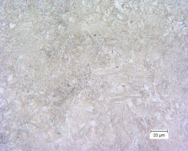
92 Figure A.3: Tempered martensite and ferrite core microstructure for AISI 8620 for gas carburising and oil quench sample 6. Figure A.4: Tempered martensite and ferrite core microstructure for AISI 3310 for gas carburising and oil quench sample 4. Figure A.5: Tempered martensite and ferrite core microstructure for AISI 3310 for gas carburising and oil quench sample 5. 75


93 Figure A.6: Tempered martensite and ferrite core microstructure for AISI 3310 for gas carburising and oil quench sample 6. Figure A.7: Tempered martensite and ferrite core microstructure for 17CrNiMo6 for gas carburising and oil quench sample 4. Figure A.8: Tempered martensite and ferrite core microstructure for 17CrNiMo6 for gas carburising and oil quench sample 5. 76


94 Figure A.9: Tempered martensite and ferrite core microstructure for 17CrNiMo6 for gas carburising and oil quench sample 6. Figure A.10: Tempered martensite and ferrite core microstructure for AISI 9310 for gas carburising and oil quench sample 4. Figure A.11: Tempered martensite and ferrite core microstructure for AISI 9310 for gas carburising and oil quench sample 5. 77


95 Figure A.12: Tempered martensite and ferrite core microstructure for AISI 9310 for gas carburising and oil quench sample 6. 78


96 A.1.2 Conventional Gas Carburising and Intensive Quench Figure A.13: Tempered martensite and ferrite core microstructure for AISI 8620 for gas carburising and intensive quenching sample 4. Figure A.14: Tempered martensite and ferrite core microstructure for AISI 8620 for gas carburising and intensive quenching sample 5. 79


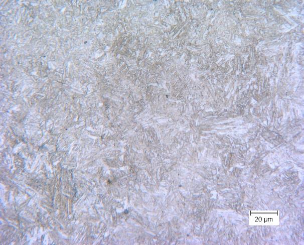
97 Figure A.15: Tempered martensite and ferrite core microstructure for AISI 8620 for gas carburising and intensive quenching sample 6. Figure A.16: Tempered martensite core microstructure for AISI 3310 for gas carburising and intensive quenching sample 4. Figure A.17: Tempered martensite core microstructure for AISI 3310 for gas carburising and intensive quenching sample 5. 80


98 Figure A.18: Tempered martensite core microstructure for AISI 3310 for gas carburising and intensive quenching sample 6. Figure A.19: Tempered martensite core microstructure for 17CrNiMo6 for gas carburising and intensive quenching sample 4. Figure A.20: Tempered martensite core microstructure for 17CrNiMo6 for gas carburising and intensive quenching sample 5. 81


99 Figure A.21: Tempered martensite core microstructure for 17CrNiMo6 for gas carburising and intensive quenching sample 6. Figure A.22: Tempered martensite with minimal ferrite core microstructure for AISI 9310 for gas carburising and intensive quenching sample 4. Figure A.23: Tempered martensite with minimal ferrite core microstructure for AISI 9310 for gas carburising and intensive quenching sample 5. 82


100 Figure A.24: Tempered martensite with minimal ferrite core microstructure for AISI 9310 for gas carburising and intensive quenching sample 6. A.1.3 Vacuum Carburising and Oil Quench Figure A.25: Tempered martensite with ferrite core microstructure for AISI 8620 for vacuum carburising and oil quenching sample 4. 83


101 Figure A.26: Tempered martensite with ferrite core microstructure for AISI 8620 for vacuum carburising and oil quenching sample 5. Figure A.27: Tempered martensite with ferrite core microstructure for AISI 8620 for vacuum carburising and oil quenching sample 6. Figure A.28: Tempered martensite with ferrite core microstructure for AISI 3310 for vacuum carburising and oil quenching sample 4. 84


102 Figure A.29: Tempered martensite with ferrite core microstructure for AISI 3310 for vacuum carburising and oil quenching sample 5. Figure A.30: Tempered martensite with ferrite core microstructure for AISI 3310 for vacuum carburising and oil quenching sample 6. 85


103 Figure A.31: Tempered martensite with ferrite core microstructure for 17CrNiMo6 for vacuum carburising and oil quenching sample 4. Figure A.32: Tempered martensite with ferrite core microstructure for 17CrNiMo6 for vacuum carburising and oil quenching sample 5. Figure A.33: Tempered martensite with ferrite core microstructure for 17CrNiMo6 for vacuum carburising and oil quenching sample 6. 86


104 Figure A.34: Tempered martensite with ferrite core microstructure for AISI 9310 for vacuum carburising and oil quenching sample 4. Figure A.35: Tempered martensite with ferrite core microstructure for AISI 9310 for vacuum carburising and oil quenching sample 5. Figure A.36: Core Tempered martensite with ferrite core microstructure for AISI 9310 for vacuum carburising and oil quenching sample 6. 87


105 A.1.4 Vacuum Carburising and Intensive Quench Figure A.37: Tempered martensite with ferrite core microstructure for AISI 8620 for vacuum carburising and intensive quenching sample 4. Figure A.38: Tempered martensite with ferrite core microstructure for AISI 8620 for vacuum carburising and intensive quenching sample 5. 88


106 Figure A.39: Tempered martensite with ferrite core microstructure for AISI 8620 for vacuum carburising and intensive quenching sample 6. Figure A.40: Tempered martensite core microstructure for AISI 3310 for vacuum carburising and intensive quenching sample 4. Figure A.41: Tempered martensite core microstructure for AISI 3310 for vacuum carburising and intensive quenching sample 6. 89


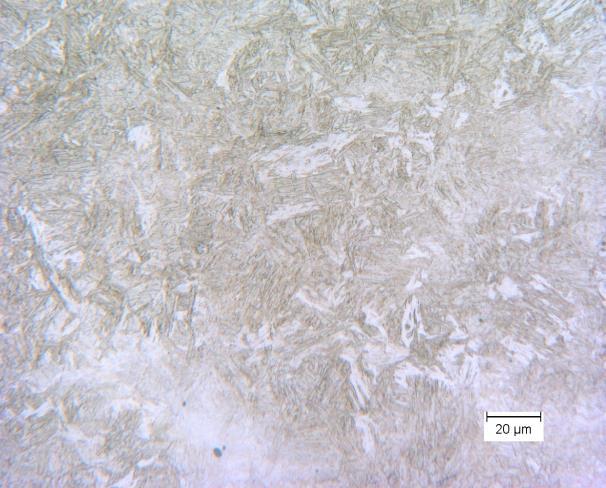
107 Figure A.42: Tempered martensite core microstructure for 17CrNiMo6 for vacuum carburising and intensive quenching sample 4. Figure A.43: Tempered martensite core microstructure for 17CrNiMo6 for vacuum carburising and intensive quenching sample 5. Figure A.44: Tempered martensite core microstructure for 17CrNiMo6 for vacuum carburising and intensive quenching sample 6. 90


108 Figure A.45: Tempered martensite with minimal ferrite core microstructure for AISI 9310 for vacuum carburising and intensive quenching sample 4. Figure A.46: Tempered martensite with minimal ferrite core microstructure for AISI 9310 for vacuum carburising and intensive quenching sample 5. 91


109 A.2 Case Microstructure A.2.1 Conventional Gas Carburising and Oil Quench Figure A.47: Martensite case microstructure for AISI 8620 for gas carburising and oil quenching sample 4. Figure A.48: Martensite case microstructure for AISI 8620 for gas carburising and oil quenching sample 5. 92


110 Figure A.49: Martensite case microstructure for AISI 8620 for gas carburising and oil quenching sample 6. Figure A.50: Martensite case microstructure for AISI 3310 for gas carburising and oil quenching sample 4. Figure A.51: Martensite case microstructure for AISI 3310 for gas carburising and oil quenching sample 5. 93


111 Figure A.52: Martensite case microstructure for AISI 3310 for gas carburising and oil quenching sample 6. Figure A.53: Martensite case microstructure for 17CrNiMo6 for gas carburising and oil quenching sample 4. Figure A.54: Martensite case microstructure for 17CrNiMo6 for gas carburising and oil quenching sample 5. 94


112 Figure A.55: Martensite case microstructure for 17CrNiMo6 for gas carburising and oil quenching sample 6. Figure A.56: Martensite case microstructure for AISI 9310 for gas carburising and oil quenching sample 4. Figure A.57: Martensite case microstructure for AISI 9310 for gas carburising and oil quenching sample 5. 95


113 Figure A.58: Martensite case microstructure for AISI 9310 for gas carburising and oil quenching sample 6. A.2.2 Conventional Gas Carburising and Intensive Quench Figure A.59: Martensite case microstructure for AISI 8620 for gas carburising and intensive quenching sample 4. 96


114 Figure A.60: Martensite case microstructure for AISI 8620 for gas carburising and intensive quenching sample 5. Figure A.61: Martensite case microstructure for AISI 8620 for gas carburising and intensive quenching sample 6. Figure A.62: Martensite case microstructure for AISI 3310 for gas carburising and intensive quenching sample 4. 97


115 Figure A.63: Martensite case microstructure for AISI 3310 for gas carburising and intensive quenching sample 5. Figure A.64: Martensite case microstructure for AISI 3310 for gas carburising and intensive quenching sample 6. Figure A.65: Martensite case microstructure for 17CrNiMo6 for gas carburising and intensive quenching sample 4. 98


116 Figure A.66: Martensite case microstructure for 17CrNiMo6 for gas carburising and intensive quenching sample 5. Figure A.67: Martensite case microstructure for 17CrNiMo6 for gas carburising and intensive quenching sample 6. Figure A.68: Martensite case microstructure for AISI 9310 for gas carburising and intensive quenching sample 4. 99


117 Figure A.69: Martensite case microstructure for AISI 9310 for gas carburising and intensive quenching sample 5. Figure A.70: Martensite case microstructure for AISI 9310 for gas carburising and intensive quenching sample


118 A.2.3 Vacuum Carburising and Oil Quench Figure A.71: Martensite case microstructure for AISI 8620 for vacuum carburising and oil quenching sample 4. Figure A.72: Martensite case microstructure for AISI 8620 for vacuum carburising and oil quenching sample

119 Figure A.73: Martensite case microstructure for AISI 8620 for vacuum carburising and oil quenching sample 6. Figure A.74: Martensite case microstructure for AISI 3310 for vacuum carburising and oil quenching sample 4. Figure A.75: Martensite case microstructure for AISI 3310 for vacuum carburising and oil quenching sample


120 Figure A.76: Martensite case microstructure for AISI 3310 for vacuum carburising and oil quenching sample 6. Figure A.77: Martensite case microstructure for 17CrNiMo6 for vacuum carburising and oil quenching sample 4. Figure A.78: Martensite case microstructure for 17CrNiMo6 for vacuum carburising and oil quenching sample


121 Figure A.79: Martensite case microstructure for 17CrNiMo6 for vacuum carburising and oil quenching sample 6. Figure A.80: Martensite case microstructure for AISI 9310 for vacuum carburising and oil quenching sample 4. Figure A.81: Martensite case microstructure for AISI 9310 for vacuum carburising and oil quenching sample

122 Figure A.82: Martensite case microstructure for AISI 9310 for vacuum carburising and oil quenching sample 6. A.2.4 Vacuum Carburising and Intensive Quench Figure A.83: Martensite case microstructure for AISI 8620 for vacuum carburising and intensive quenching sample


123 Figure A.84: Martensite case microstructure for AISI 8620 for vacuum carburising and intensive quenching sample 5. Figure A.85: Martensite case microstructure for AISI 8620 for vacuum carburising and intensive quenching sample 6. Figure A.86: Martensite case microstructure for AISI 3310 for vacuum carburising and intensive quenching sample


124 Figure A.87: Martensite case microstructure for AISI 3310 for vacuum carburising and intensive quenching sample 6. Figure A.88: Martensite case microstructure for 17CrNiMo6 for vacuum carburising and intensive quenching sample 4. Figure A.89: Martensite case microstructure for 17CrNiMo6 for vacuum carburising and intensive quenching sample


125 Figure A.90: Martensite case microstructure for 17CrNiMo6 for vacuum carburising and intensive quenching sample 6. Figure A.91: Martensite case microstructure for AISI 9310 for vacuum carburising and intensive quenching sample 4. Figure A.92: Martensite case microstructure for AISI 9310 for vacuum carburising and intensive quenching sample