Phased Array Applications
|
|
|
- Antony Gray
- 5 years ago
- Views:
Transcription
1 Phased Array Applications


2 Omniscan Phased Array Inspection of Plate/Butt Welds 40 degree beam 70 degree beam 2

3 Phased Array Inspection of Plate/Butt Welds Omniscan analysis view of one-line scan using degree sector scan. Red areas on C scan display non fusion in the weld. 3

4 Phased Array Inspection of Plate/Butt Welds Omniscan analysis view of one-line scan using 65 degree linear scan. Red areas on C-scan display non fusion in the weld. 4

5 Phased Array Inspection of Plate/Butt Welds Tomoview offline (computer based) analysis of Omniscan phased array data file. S-scan, C-scan, D-scan, and B-scan displaying slag inclusions in 12.7mm V weld 5

6 Phased Array Inspection of Plate/Butt Welds Tomoview offline analysis of Omniscan phased array data file. Linear 70 degree scan displaying an ID connected root crack. 6

7 Phased Array Inspection of Plate/Butt Welds Tomoview offline analysis of Omniscan phased array data file. Volumetric merge of all focal laws displaying root crack, excessive drop through, slag, and a toe crack. 7


8 Construction Welding:Tee Fillet joint welding Inspection of Tee joint welding for bridge structures under fabrication and in-service Description of the Solution - Manual inspection using one small phased array probe - One-line scan at around 25 mm/s, one side at a time - Inspection with 40- to 70-degree refracted angle - Real-time display of sectorial scan and Ascan Accurate depth measurement of fillet welds 8

9 Flange Corrosion Under Gasket The inspection is performed using a 16 element phased array probe with a 45 degree fixed angle initializing a sector scan (azimuthal or sectorial scan) from 30 to 85 degrees. A 45 degree fixed angle wedge with a 61/2 diameter ratios (additional shaping is required using sand paper to shape the wedge to the 15 degree angle of the flange neck) was place at the end of the weld (neck of the flange) this can be used as a guide to ensure maximum coverage with the bolts intact. (Bolts may cause obstruction during field exam). 9

10 Flange Corrosion Under Gasket Results The first indication presented in the A scan at is the ¼ flat bottom hole. The flaw is easily detected at 74 degrees shear. The indication presented at is a reflector of the back surface from degrees. The third indication not present in the A scan or B scan is the corner trap represented in the lower angles. 10

11 Phased Array Inspection of Socket Welds Using a 5MHz 10 Element probe with the wedge contoured to fit the.75 inch pipe, the phased array inspection is performed by building a C-scan by doing a one line scan around the socket weld. 11


12 Phased Array Inspection of Socket Welds degree phased array sector scan of.75 inch socket weld displaying flaw area in A-scan, S-scan, and C-scan. 12
13 Phased Array Inspection for HIC Detection in Vessels Many pre-service defects such as laminations and inclusions are in the vessels that are not considered detrimental to the vessel. The difficulty is differentiating spot inclusions and laminations from side step cracking (HIC) 13

14 Omniscan Phased Array Inspection for HIC Detection in Vessels Using a longitudinal sector scan from -30 degrees to +30 degrees the side step cracking can be easily seen in the S-scan and A-scan making the inspection much less dependent on the skill of the operator than with conventional UT. 14

15 Phased Array Inspection for HIC Detection in Vessels Another example of rejectable side step cracking (HIC) compared to acceptable spot inclusions not considered detrimental to the vessel. As the inspector slowly moves the probe forward and backward and side to side, the HIC will grow and fade as the amplitude changes between the facets of the side step cracking. 15

16 Phased Array Inspection Bridge Pin Bolting Using a longitudinal sector scan from -15 to 15 degrees, all areas of the bridge pin bolting can be inspected from one surface. Total length on pin is 10 inches 16
17 Phased Array Inspection Bridge Pin Bolting While viewing the 12.5 degree focal law, the upper threads, the EDM notch in the bolt body, and the backwall of the lower lip can be seen in the S-scan and A-scan. 17

18 Phased Array Inspection Bridge Pin Bolting Another example of EDM notch detected in upper thread area and lower body of bridge pin. 18
19 Thread Inspection PA L Wave at 0 Degree 19
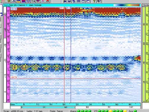
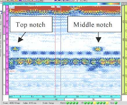
20 Thread Inspection Good Part 20
 and the tip can be detected by the phased array.")
21 Phased Array Inspection Cracked Vessel Sample Using a degree sector scan, both the base of the crack (corner trap) and the tip can be detected by the phased array.. 21

22 Phased Array Inspection Cracked Vessel Sample Base of the crack and the tip of the crack detected in the S-scan 22

23 Phased Array Inspection of ERW Seam Weld One line degree sector scans for a full volumetric inspection of seam welds. The primary defect is non-fusion and surface laps in the seam weld. 23

24 Phased Array Inspection of ERW Seam Weld One line degree sector scans showing surface connected lap in the weld seam. 24

25 Phased Array Inspection of ERW Seam Weld One line degree sector scan inspection of the weld in the first slide. Non-fusion, cracks, and laps can be seen in the C-scan, S-scan and A-scan. 25

26 Phased Array Inspection of ERW Seam Weld Computer based offline analysis of data file. 26

27 Phased Array Inspection of Riser Nuts Typical Omniscan application using longitudinal wave sector scan focused at the area of interest in the nut. 27

28 Phased Array Inspection of Riser Nuts.050 EDM notch in shallow area of body wall 28

29 Phased Array Inspection of Riser Nuts.050 inch EDM notch in middle area of threaded section 29


30 Phased Array Inspection of Heat Exchanger Body Typical ASME Sec. V Code Case 2235 inspection using degree encoded sector scans. Welding process is SAW producing smooth clean welds. 30

31 Phased Array Inspection of Heat Exchanger Body Display showing non-fusion area weld. The reflectors in the top of the C-scan are geometric reflectors seen from the holes in the previous slide. The defect area is in the C-scan cross hairs and displayed in the sector scan. 31

32 Phased Array Inspection of Heat Exchanger Body Analyzing the data offline on R/D Tech s computer based software Tomoview allows for use of custom views, display linking, amplitude drop sizing tools, volumetric measuring tools, detailed statistics using measure cursors, etc. 32

33 Phased Array Inspection of Heat Exchanger Body C scan display of a volumetric merge of all focal laws (45-70 degrees). The merged top view allows the operator to view the maximum amplitude signal for any focal law within the inspected volume. This makes the analysis fast and simple. 33

34 Phased Array Inspection of ID Connected Toe Crack in37mm Coke Drum Vessel The flaw is seen by sector scans from both sides of the weld. 34

35 Phased Array Inspection Dissimilar Metal Welds in Riser Piping Inspection Details: 50mm wall thickness, carbon steel base material, inconel weld and 5mm thick inconel clad layer on the ID surface. Full volumetric inspection of weld and HAZ requires multiple one line scans from both sides of the weld degree refracted longitudinal sector scans are used on all one line scans. 35


36 Phased Array Inspection Dissimilar Metal Welds in Riser Piping For the original detection scans, all focal laws are focused on the angle of the weld bevel. Supplemental sizing raster scans are performed focusing all the focal laws at the actual depth of detection. 36
 and inconel weld (6100 m/sec).")
37 Phased Array Inspection Dissimilar Metal Welds in Riser Piping Calibration was performed by adjusting the gain for one center focal law to 80% amplitude. Minor adjustments were made in analysis mode to compensate for the difference between the longitudinal velocity in the carbon steel base metal (5900m/sec) and inconel weld (6100 m/sec). This is only possible if a calibration standard of the same material and weld is available with known reflectors in the weld centerline, weld face, and ID. 37

38 Phased Array Inspection Dissimilar Metal Welds in Riser Piping ID connected flaw in the inconel clad layer weld root. 38

39 Phased Array Inspection Dissimilar Metal Welds in Riser Piping Mid wall flaw in weld centerline. 39

40 Phased Array Inspection Dissimilar Metal Welds in Riser Piping Mid wall flaw in far side of weld. This is the most difficult area to inspect because the ultrasound must travel through the longest section of inconel weld to arrive at the flaw. 40

41 Phased Array Inspection Dissimilar Metal Welds in Riser Piping Shallow flaws in upper 5mm of weld 41

42 Phased Array Inspection Dissimilar Metal Welds in Riser Piping Supplemental raster scans for flaw sizing showing upper and lower tip diffraction of embedded flaw. 42