Composites Processing ver. 1 ME 4210: Manufacturing Processes and 1 Engineering Prof. J.S. Colton GIT 2009
|
|
|
- Samson Page
- 5 years ago
- Views:
Transcription
1 Composites Processing ver. 1 1
2 Definition A microscopic mixture of two or more different materials. One typically being the continuous phase (matrix), and the other being the discontinuous phase (reinforcement). Its properties are strongly dependent d on the composite structure. Ductility of matrix combined with stiffness of reinforcement. 2


3 Ceramic fiber composite Polymer matrix composite 3
4 People Trees Types / Examples Fiber reinforced matrices fiberglass - epoxy Particulate reinforced matrices tires (carbon black in rubber, but it also has continuous fibers (steel or polymer belts)) 4
5 Fibers/Particles Reinforcement Glass Kevlar Carbon Thermoplastics Alumina Boron SiC Steel Silica Glass beads Talc Rocks Carbon black Calcium carbonate Si 3 N 4 5
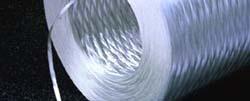

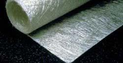
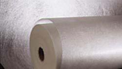
6 Reinforcements Rovings continuous bulk Continuous strand mat Chopped strand mat Surface veils 6


7 Matrices Protects & separates reinforcement, transmits forces Polymer PEEK, epoxy, polyester, polyurethane, rubber Metal Al, Cu, Ni, Ti Ceramic glass, cement 7
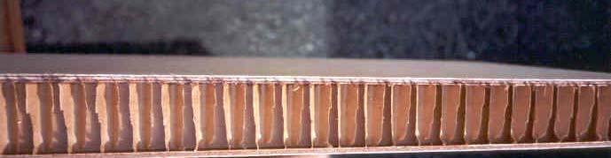
8 Honeycomb composites 8
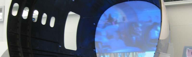
9 C-17 Aircraft 9
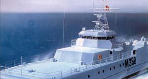
10 Visby Corvette 10
11 IsoTruss Bike 11
12 Hand lay-up Processes Vacuum bagging/autoclave Compression molding SMC/BMC Liquid resin molding Resin transfer molding 12
13 Processes Pultrusion Filament winding Injection molding Thermoplastics processing Automated tape laying 13


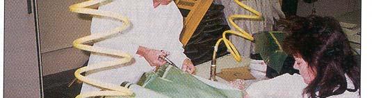
14 Manual lay-up Definition: A process wherein the application of resin and reinforcement is done by hand onto a suitable mold surface. The resulting laminate is allowed to cure in place without further treatment 14


15 Hand spray-up 15
16 Hand lay-up shop 16


17 Molds 17
18 Mold 18
19 Vacuum bag assembly 19


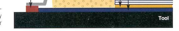
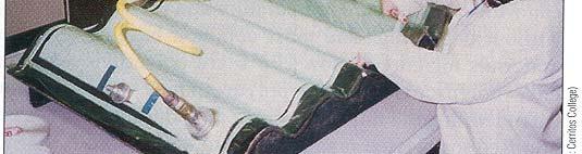
20 Vacuum bag Breather Bleeder 20
21 Lay-up Material ilon stiffening i structure Vacuum bag and fittings attached 21
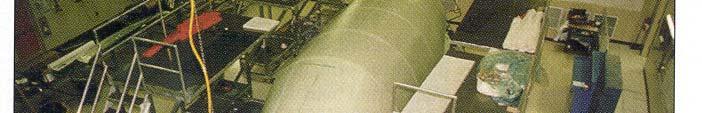
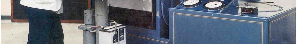
22 Autoclave 22
23 Autoclave 23
24 Delta II Rocket 24


25 Delta II rocket 25
26 Can be used with bulk molding compound (BMC) 26


27 27
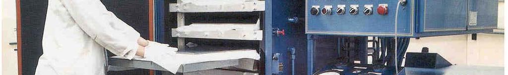
28 Schematic of a compression molding press 28
29 Car parts with Sheet Molding Compound (SMC) - Prowler 29
30 SMC manufacture using a configuration that can make chopped-fiber SMC-R; continuous fiber SMC-C; or continuous, random SMC-C/R material 30
31 Molding process 31
32 Fiber orientation 32

")
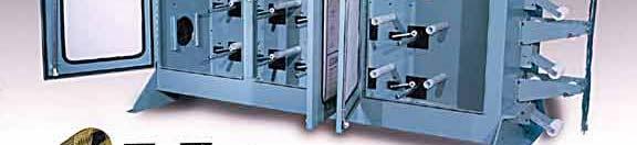
33 Resin transfer molding (RTM) process 33
34 RTM applications Auto body panels Truck air deflectors Wind blades Chemical storage tanks Solar collectors (40 ft diameter, 36 parts) RV components Propellers Bathtub/shower units Antenna dishes Chairs Swim pool panels 34


35 Car parts 35
36 RTM automobile structure t 36


37 Truck 37
38 Train Compartment 38
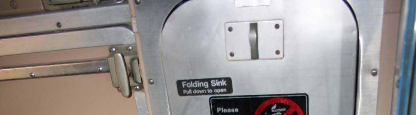


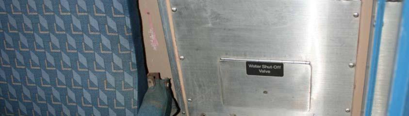
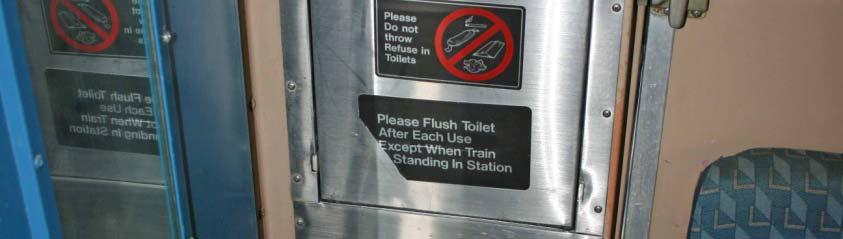
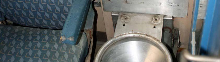


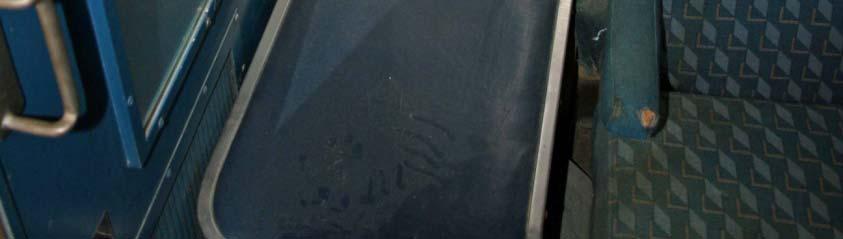
39 Train Compartment 39
40 Plenum method for making preforms 40
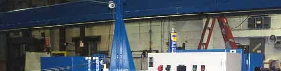
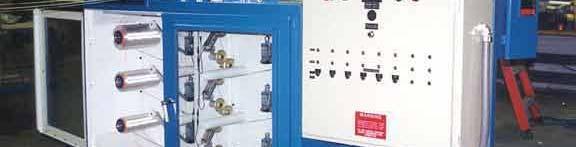
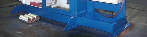
41 Schematic of high-speed RTM process 41
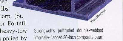
42 42
43 SCRIMP Boat Hulls 43
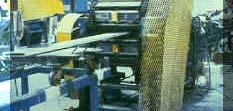
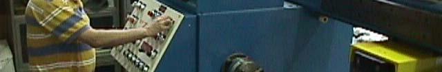
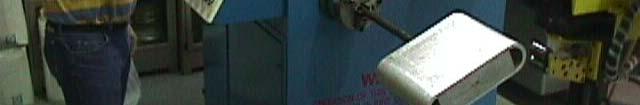
44 Pultrusion process 44


45 Fiber let-off Preforming Curing die Fiber guides Cut-off saw Resin impregnation Puller 45
46 Reinforcements Rovings continuous bulk Continuous strand mat Chopped strand mat Surface veils 46
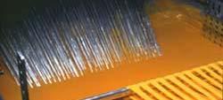
47 Continuous fiber reinforcement pultusion 47
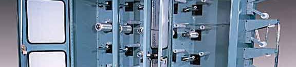
48 Hollow structure pultrusion process 48
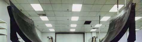
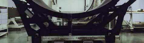
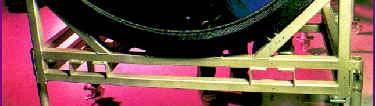
49 RIM (Reaction Injection Molding) pultrusion 49
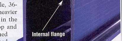
50 Exploded view of pultruded composite 50


51 Bank of America Building Spire 51


52 Pultruded bridges 52

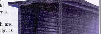


53 Pultruded I-beam 53
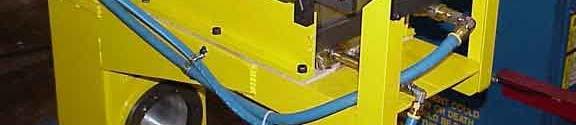
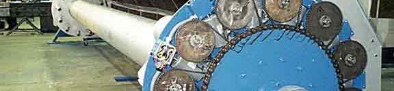
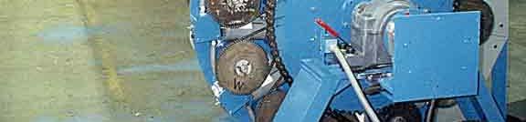
54 Filament winding 54


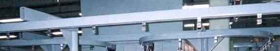
55 GT s machine 55


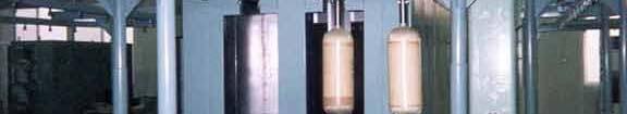
56 Filament winding machines 56


57 Delta IV Rocket faring mandrel 57
58 Reusable Mandrels Figure 1: A Veriflex e cylinder is fabricated. Figure 2: The cylinder is placed in a clamshell mold, heated, and blow-molded into a complex-shaped mandrel. 58
59 Reusable Mandrels Figure 3: The mandrel is cooled below the transition temperature resulting in a rigid mandrel. Figure 4: The mandrel is filament-wound and then cured. The cure process for the composite does not affect the mandrel. 59
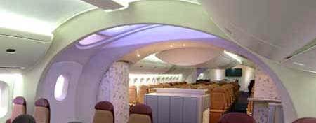
60 Reusable Mandrels Figure 5: After the composite is cured, the Veriflex mandrel is heated above its activation ation temperature. re The Veriflex then becomes pliable and is removed. The transition temperature does not affect the composite. Figure 6: The complex part is completed. The cylindrical Veriflex mandrel, which returned to its "memory" shape while above its transition temperature, can be reused. 60
61 Creel tensioners 61


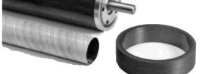
62 Integral head resin wet-out bath 62
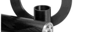
63 Winding pins for low angle winding 63

64 Continuous curing oven 64
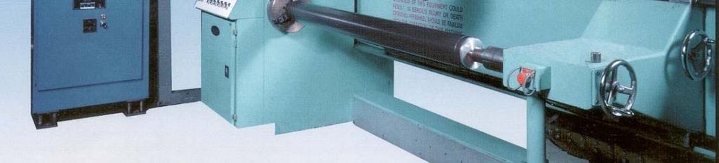
65 Layout of a computer-controlled filament-winding machine 65
66 Gas tanks 66

67 Aerospace parts F-16 Patriot missile Soviet missile 67


68 Tape laying 787 fuselage 68


69 Tape laying 787 fuselage 69
70 Composite motors 70

71 Sporting goods 71
72 Glass epoxy filament-wound 9-foot-diameter by 55-foot- long assembled railway tank car 72


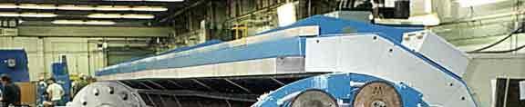
73 Pipe machine and cure oven 73


74 Light pole 74
75 Thermoplastics processing 75
76 Injection molding Clamp Mold Barrel Hopper 76
77 Injection molding clamp nozzle pellets barrel hopper throat mold cavity screw heaters motor / drive 77
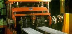
78 Roll forming 78
79 Roll-formed part 79
80 Matched die forming adjustment bolts sample and holder alignment pins weights 80
81 Press forming of LDF (long discontinuous fibers) Heat material Transfer into heated dies Clamp and thermoform Formed component after trimming 81
82 Compression molding 82
83 Compression molding sequence 83
84 Hydroforming 84
85 Diaphragm forming 85
86 Diaphragm forming 86
87 Vacuum forming in autoclave 87
88 Stretch forming 88
89 Tape laying 89
90 90
91 Automated Tow Placement - Thermoplastics 91

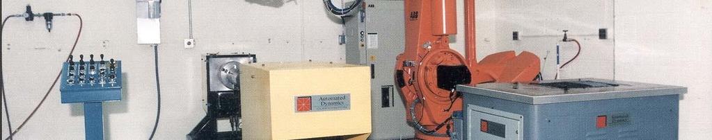
92 Robotic thermoplastic ATP machine NASA Langley 92


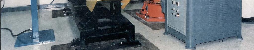
93 Filament winding thermoplastic ATP machines 93


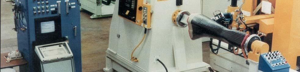
94 Filament winding thermoset ATP machine 94
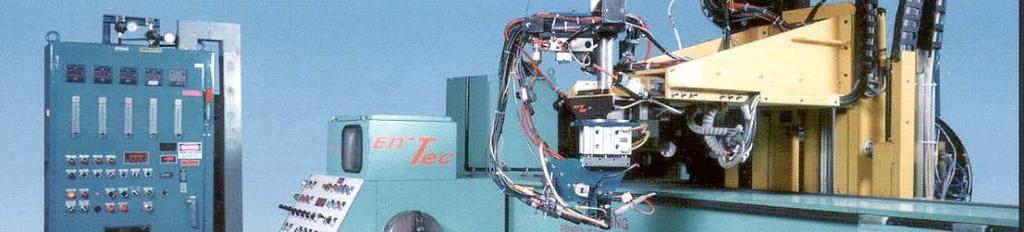
95 Large ATP machine 95

96 Typical parts 96
97 97