High Speed Railway Fastening System Technology. Anyang Railway Equipment Co., Ltd
|
|
|
- Yanli Xu
- 2 years ago
- Views:
Transcription


1 High Speed Railway Fastening System Technology
2 High Speed Railway Fastening System Technology Rail fasteners: It is the part used to connect the rail and sleeper on the track. The function is to fix the rail on the sleeper, maintain the gauge and prevent the rail from moving vertically and horizontally relative to the sleeper.


3 High Speed Railway Fastening System Technology Fastening systems for high-speed railways are divided into two categories, one is ballasted track fasteners, and the other is ballastless track fasteners. Ballasted rails mainly adopt three types of fasteners: spring clip type-iv, spring clip type-v and spring clip type- FC. According to the basic form of the rail, they are divided into shoulder and non-baffle fasteners, spring clip type-iv and spring clip type-fc is a sleeper without shoulder fastener, and the elastic type-v is a sleeper with a shoulder fastener. The ballastless track mainly uses WJ-7, WJ-8, W300-1 and SFC fasteners. According to the form of ballastless bed, it is divided into non-shoulder and shoulder fasteners. WJ-7 and SFC are Fasteners without shoulders, WJ- 8 and W300-1 are fasteners with shoulders.
 are composed of spring clips, rail shoulders, rail insulators and rubber pads.")
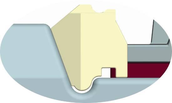
4 High Speed Railway Fastening System Technology Spring clip type-iv fasteners Spring clip type-iv fasteners (hereinafter referred to as fasteners) are composed of spring clips, rail shoulders, rail insulators and rubber pads. spring clip insulator rubber pad shoulder
5 Spring Clip(type- Ⅳ) High Speed Railway Fastening System Technology There are three types of sping clips: C4 type, JA type and JB type. Generally, C4 spring clips are installed, and JA and JB spring clips are installed at the rail joints. The diameter of C4 spring clips is 20 mm, and the diameter of JA and JB spring clips is 18 mm. The anti-corrosive paint for JA spring clips is gray, and it is used with the insulating gauge blocks of No. 7, 8 and 9 joints; the anti-corrosion paint for JB spring clips is black, and it is used with No. 10, 11, 12 and 13 joints. Equipped with rail insulators. φ20mm φ18mm φ18mm C4 Spring Clip JA Spring Clip JB Spring Clip
6 High Speed Railway Fastening System Technology Rail Shoulders This part is embedded in the sleeper in advance, and the embedding accuracy should meet the size requirements of the following figure. Foot distance between outside of two shoulders mm~1685mm 34.2mm~35.8mm 170.5mm~172.5mm 27.2mm~28.8mm
 are divided into two types, namely rail insulators G4 are used in")


7 High Speed Railway Fastening System Technology Rail Insulators Rail insulators (hereinafter referred to as gauge blocks) are divided into two types, namely rail insulators G4 are used in general areas and rail insulators G4J are used at rail joints. Each rail insulator has 7 specifications, namely 7th, 8th, 9th, 10th, 11th, 12th and 13th. 9th and 11th are used in the standard gauge. Except for the rail insulators of 7th, 8th and 9th connectors which are not black, the other gauge blocks are all black. Different thickness d C o r r e s p o n d i n g t o different numbers d Joint Insulators

8 High Speed Railway Fastening System Technology Special Note: This fastener cannot be used to adjust the height of the rail by inserting the height-adjusting pad. The use of this fastener must not install a height-adjusting pad under the rail to avoid residual deformation or even breakage of the sping clip.
9 High Speed Railway Fastening System Technology Fastener laying sequence and requirements Preparation before installation Prepare 9th and 11th insulators, and appropriately prepare 8th, 10th and 12th insulators to prepare for adjusting the gauge when the gauge is not suitable; at the same time, properly prepare the corresponding number of joint gauge blocks. To prepare for rail joints. Prepare C4 spring clips, and prepare JA and JB spring clips appropriately for rail joints. The buried position of the rail shoulders in the upper track sleeper must be accurate. Sleepers where the embedded position of the rail shoulder is skewed, upturned or embedded height, the distance between the two shoulders on the same side, or the bottom corner distance of the two outer shoulder does not meet the requirements, shall not be used on the track.

10 High Speed Railway Fastening System Technology Remove the mud from the sleeper bearing rail surface between the two rail shoulders and the mortar in the holes of the rail shoulders. Remove the mud from the sleeper bearing rail surface between the two rail shoulders Remove the mortar in the holes of the rail shoulders.

11 High Speed Railway Fastening System Technology Remove the sludge from the bottom of the rail Remove mud from the bottom of the rail


12 High Speed Railway Fastening System Technology Fastenerlaying sequence and requirements Laying rubber pads Place the rubber pad between the two rail shoulders, and the center line of the notch on both sides of the rubber pad should be aligned with the center line of the rail shoulders. The middle picture shows the wrong orientation of the rubber pad, and the right picture shows the correct orientation.

13 Laying the rails High Speed Railway Fastening System Technology Install the gauge block Install 9th and 11th insulators, and the ears of the insulators should be fastened to the rail shoulders. If due to manufacturing deviations of rails, sleepers, and insulators, the insulators with the specified numbers cannot meet the gauge requirements or the insulators cannot be installed in place, they can be replaced according to the actual situation, and no violent knocks are allowed to make them fit in.


14 High Speed Railway Fastening System Technology No violent knocks are allowed to make them fit in.

15 High Speed Railway Fastening System Technology Special note: joint insulator G4J should be used at the rail joint Joint insulators G4J


16 High Speed Railway Fastening System Technology Install spring clips Before installing the spring clips, the rails, rubber pads, sleeper bearing rail surfaces, and insulators buckling rail surfaces should be closely attached to the upper surface of the rail bottom.


17 High Speed Railway Fastening System Technology Special tools should be used when installing the spring clips.


18 High Speed Railway Fastening System Technology The position of the middle limb of the elastic clilp should be placed flat and upright, and should not be skewed. Don't pull hard during installation, the force must be moderate, and the fulcrum and the force point must be correct.
19 High Speed Railway Fastening System Technology If you encounter difficulty in positioning individual spring clips, you can tap the tail of the spring clips with a small hammer while using the installation tool to make them in place.


20 High Speed Railway Fastening System Technology The position of the spring clip is based on the distance between the inner side of its small arc and the end of the rail shoulder by 8-10 mm. distance is 8~10mm Must not be tight or too far apart.

21 Special Note: High Speed Railway Fastening System Technology JA and JB spring clips should be installed at the rail joints. The gray JA type spring clip is used with the non-black 7th, 8th, 9th insulators, and the black JB type spring clip is used with the black 10th, 11th and 12th insulators. Install joint spring clips and insulators at rail joints

22 High Speed Railway Fastening System Technology The gray JA-type spring clips are used with the non-black insulators of 7th, 8th, 9th joints. + The black JB spring clip is used with the black 10th, 11th, 12th joint insulators. +
 to remove the")
23 High Speed Railway Fastening System Technology Installation adjustment Check the gauge. If there is any problem, use a special tool (same as the installation tool) to remove the spring clip.

24 High Speed Railway Fastening System Technology Check according to the gauge adjustment amount, select the appropriate gauge block model to install according to the following table. Standard Gauge 1435mm+Gauge Adjustment d d a b c d
25 High Speed Railway Fastening System Technology Gauge Adjustment (mm) Left Rail 右股钢轨 Outside a Inside b Inside c Outside d
26 High Speed Railway Fastening System Technology Change gauge block
27 High Speed Railway Fastening System Technology Fastener maintenance requirements At the early stage of operation, attention should be paid to observe the use of sleepers and fasteners. When sleepers are found to be empty, high, low, and level irregular or triangular pits, they should be tamped in time, and height-adjusting pads should not be used for rail height-adjusting operations. If it is found that the gauge block is broken, the rubber pad is broken or the elastic clip is broken during use, it should be replaced in time. When carrying out the stress relief of the seamless track, the spring clip must be removed with a special tool (same as the installation tool). After the stress is relieved, check whether the positions of the rubber pad and the gauge block are correct. If there is any misalignment, install the spring clip after adjustment.

28 High Speed Railway Fastening System Technology V-type Spring Clip Fastener Components V-type Spring Clip Fastener (hereinafter referred to as fasteners) are composed of screw spikes, flat washers, spring clips, gauge baffles, under-rail pads and rail dowels. In addition, for the needs of rail height adjustment, it also includes height adjustment pad. screw spike rubber pad height-adjusting pad flat washer spring clip gauge baffle dowel
29 High Speed Railway Fastening System Technology Spring Clip and Under Rail Pad There are two types of spring clips: W2 spring clips used in general areas and X3 spring clips that may be used on bridges. The diameter of W2 spring clips is 14 mm and the diameter of X3 spring clips is 13 mm. In addition, as a spare part, I-type fasteners and A-type spring clips may be used at rail joints. The under-rail pad is divided into two types: the rubber pad RP5 used in general sections and the composite pad CRP5 that may be used on the bridge. When it is necessary to reduce the line resistance on the bridge, the X3 elastic clip and the composite pad can be used. At this time, the longitudinal resistance of the rail for a single set of fasteners is 4kN.
30 use in general areas High Speed Railway Fastening System Technology φ14mm + use in bridge areas W2 spring clip rubber pad RP5 φ13mm + X3 spring clip composite pad CRP5


31 High Speed Railway Fastening System Technology Gauge Baffle There are seven types of gauge baffle G5, namely 2#, 3#, 4#, 5#, 6#, 7#, 8#. 4# and 6# are used in the standard gauge. d Take 6# as an example to illustrate the product mark Different distances d correspond to different numbers


32 Railway Dowels High Speed Railway Fastening System Technology The component is pre-embedded in the sleeper, the embedding accuracy should meet the requirements, and the top surface of the dowel should be flush with the sleeper bearing rail surface. After the dowel is buried, it should be covered with a plastic (or other material) cover to prevent rainwater and mud from entering. covered with a plastic (or other material) cover to prevent rainwater and mud from entering
33 High Speed Railway Fastening System Technology Height Adjustment Pad The height adjustment pad TD5 is divided into four specifications of 1 mm, 2 mm, 5mm and 8 mm according to the thickness, and is placed between the pad under the rail and the sleeper bearing rail surface. 1mm d U n d e r - r a i l H e i g h t Adjustment Pad 2mm 5mm 8mm
34 High Speed Railway Fastening System Technology Fastener laying sequence and requirements Preparation before installation According to 1.1, select and prepare the appropriate type of spring clip(w2 or X3 type) and the appropriate type of under-rail pad (rubber pad RP5 or composite pad CRP5). Properly prepare spring clips for I-type fasteners and A-type spring clips for rail joints. According to the selection, prepare 4# and 6# gauge baffles, and appropriately prepare 3#, 5# and 7# gauge baffles to prepare for adjusting the gauge when the gauge is not suitable.

35 High Speed Railway Fastening System Technology Standard Gauge 1435mm+Gauge Adjustment a b c d
36 1 1 Gauge Adjustment (mm) High Speed Railway Fastening System Technology Left Rail Right Rail Outside a Inside b Inside c Outside d

37 High Speed Railway Fastening System Technology Properly prepare the height-adjusting pad for the purpose of adjusting the height of the rail. Remove the mud from the bearing rail surface and the bottom of the sleeper. Remove silt and debris from sleepers Remove mud from the bottom of the rail
 cover on the")
38 High Speed Railway Fastening System Technology Remove the plastic (or other material) cover on the dowels.

39 High Speed Railway Fastening System Technology Installation sequence in normal installation state Laying under-rail pads Place the under-rail pad in the middle of the bearing rail surface, and the flange of the pad should buckle the bearing rail surface.

40 High Speed Railway Fastening System Technology The flange of the rubber pad under the rail should buckle the bearing rail surface The under-rail pads are not allowed to be offset
41 High Speed Railway Fastening System Technology Laying the rails
42 High Speed Railway Fastening System Technology Install the gauge baffle Install 4# and 6# gauge baffles. The gauge baffles should be placed between the two ears of the pad under the rail. If due to manufacturing deviations of rails, sleepers and gauge baffles, the gauge baffle with the specified number cannot meet the gauge requirements or the gauge baffle cannot be installed in place, it can be replaced according to the actual situation.


43 High Speed Railway Fastening System Technology
44 Install spring clips High Speed Railway Fastening System Technology screw spikes flat washers The threaded part is coated with railway special protective grease

45 High Speed Railway Fastening System Technology Nut torque: Tightening torque of W2 spring bar is about 160 N m The tightening torque of X3 elastic strip is about 95 N m tighten tighten
46 High Speed Railway Fastening System Technology The lower jaw in the middle of the spring clip is in contact with the rail Lower jaw in the middle of the spring clip
47 High Speed Railway Fastening System Technology Special note: At the rail joints, when it is difficult to install the W2 and X3 spring clips on the small gauge baffle, you should install the spring clips type I fasteners and type A spring bars. A-type spring clip

48 High Speed Railway Fastening System Technology Installation sequence for heightened state Adjust the gauge and orbit If there is a small amount of unevenness in the height and level of the rail, consider putting in a height-adjusting pad. At this time, the steel rail should be lifted, and the height-adjusting pad should be placed under the pad under the rail and the edge ears of the pad should be clamped to the gauge baffle.


49 High Speed Railway Fastening System Technology The height-adjusting pad should be placed under the rail pad

50 High Speed Railway Fastening System Technology Special reminder: The height-adjusting pad must not be placed on the under-rail pad, the total thickness of the put-in height-adjusting pad shall not be greater than 10 mm, and the number of the height-adjusting pad shall not exceed 2 pcs. The total thickness of the height-adjusting pads placed in must not be greater than 10mm, and the number of height-adjusting pads must not exceed 2 pcs.

51 High Speed Railway Fastening System Technology The gauge baffle should be placed between the ears of the height-adjusting pad and the under-rail pad, and shall not be pressed against the height-adjusting pad and the under-rail pad.
52 High Speed Railway Fastening System Technology Maintenance requirements At the early stage of operation, attention should be paid to observe the use of fasteners and sleepers. If the fasteners are loosened due to residual compression of the under-rail pad, they should be re-tightened in time. When there are empty sleepers, uneven height and level, or triangular pits, the starting tamping should be carried out in time. If there is a small amount of height and unevenness that are difficult to carry out the starting tamping operation, the height-adjusting pad can be inserted. Special reminder: The total thickness of the height-adjusting pad should not be greater than 10 mm. If the fastener parts are found to be damaged during use, they should be replaced in time. Before starting the tamping operation of the large-scale road maintenance machinery, all the height-adjusting pads should be removed. After the starting tamping operation is completed, if there is a small amount of unevenness in the height and level of the individual section of the rail, the height-adjusting pad can be placed in accordance with 2.3. When it is necessary to remove the screw spikes, avoid mud and dirt from entering the dowels.
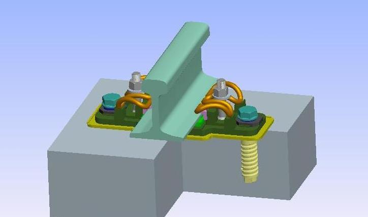
53 Assembly and laying of WJ-7 type fasteners 1. WJ-7 type fastener components and description WJ-7 type fasteners (hereinafter referred to as fasteners) are composed of T-bolts, nuts, flat washers, spring bars, insulating blocks, iron tie plates, under-rail pads, insulating cushion pads, heavy spring washers, flat spacers, anchor bolts and rail dowels. In addition, in order to adjust the height of the steel rail, it also includes height adjustment pad under rail and height adjustment pad under iron tie plates.

54 insulator anchor bolt sping clip nut flat washer heavey spring wahser flat spacer iron tie plate insulating cushion pad rubber pad T- bolt height-adjusting pad under rail height-adjusting pad under iron tie plate dowel
55 1.1 Spring clips and under-rail pads There are two types of spring clips, namely the W1 type used in general sections and the X2 type that may be used on the bridge. The diameter of the W1 spring clip is 14mm, and the diameter of the X2 spring clip is 13mm. The under-rail pads are divided into two types: A and B. Type A is used for passenger dedicated lines that take into account freight, and Type B is used for passenger dedicated lines. Each type is divided into two types: rubber pads used in general sections and composite pads that may be used on bridges. Kind. When the line resistance needs to be reduced on the bridge, X2 elastic clips can be used with composite plates. At this time, the rail longitudinal resistance of a single group of fasteners is 4kN.

56 use in general sections φ14mm + W1 spring clip possible use on bridge φ13mm rubber pad + X2 spring clip composite pad


57 1.2 Dowel The component is embedded in the sleeper or track slab in advance, and the embedding accuracy should meet the requirements, and the top surface of the dowel should be flush with the bearing surface of the sleeper or track slab. After the dowel is buried, it should be covered with a plastic (or other material) cover to prevent rainwater and mud from entering. cover with plastic (or other materials) to prevent ainwater and mud from entering

58 1.3 Height adjustment pad The height-adjusting pad is divided into two types, the height-adjusting pad under rail and height-adjusting pad under iron tie plate, which are respectively placed between the under-rail pad and the iron tie plate, between the iron tie plate and the insulating cushion pad. The height-adjusting pad under rail is divided into four specifications according to the thickness of 1 mm, 2 mm, 5 mm and 8 mm; the height-adjusting pad under the iron tie plate is divided into two specifications of 5 mm and 10 mm according to the thickness. 1mm d 2mm 5mm 8mm height-adjusting pad under rail pad height-adjusting pad under iron tie plate d 5mm 10mm
 and suitable types of underrail pads (type A and type B rubber pads or composite pads). 2.1.2 Properly prepare the height-adjusting pads under the rail to prepare for minor adjustment of the height of the rail.")
59 2 Fastener laying sequence and requirements 2.1 Preparations before installation According to 1.1, select and prepare suitable types of spring clips (Type W1 or X2) and suitable types of underrail pads (type A and type B rubber pads or composite pads) Properly prepare the height-adjusting pads under the rail to prepare for minor adjustment of the height of the rail. Remove the sludge and debris on the bearing rail surface of the sleeper or track plate. Remove the sludge at the bottom of the rail Remove the mud from the bearing surface of the sleeper or track slab and the bottom of the rail. Remove silt and debris on the bearing surface of sleepers or track slabs remove mud from the bottom of the rail
 cover on the")
60 2.1.4 Remove the plastic (or other material) cover on the dowel.

61 2.2 Installation sequence in normal installation state Step 1: Place the insulating cushion pad Lay an insulating cushion pad to align the hole of the pad with the hole of the dowel.


62 Step 2: Place the iron tie plate Place the iron tie plate so that the rail bottom slope faces the inner side of the track (in the direction of the arrow on the iron tie plate). The center of the bolt hole of the iron tie plate should be aligned with the center of the dowel.


63 The following picture shows the effect picture after installing two iron tie plates on a single sleeper. inside of rail


64 Step 3: Place the long side short side long side of the flat spacer. Place the flat spacer on the iron spacer, and make the flat spacer face inward from the longer side of the center of the circular hole. short side long side long side short side

65 Step 4: Place heavy spring washers and anchor bolts Put the anchor bolts on the spring washers, and coat the threaded part with railway special protective grease, and screw them into the dowel. Before tightening the anchor bolts, adjust the position of the iron tie plate so that the marking line on the iron tie plate is aligned with the marking line on the flat cushion block. 1 2 anchor bolt spring washer railway special protective grease


66 3 Screw into the dowel and tighten The marking lines on the iron tie plate and the flat spacer should be aligned


67 Step 5: Place the pad under the rail Place the under-rail pad on the supporting rail surface of the iron pad. Take the rubber pad as an example. The picture on the left shows the wrong orientation of the rubber pad, and the picture on the right shows the correct orientation. Incorrect installation of rubber pad position Correct installation of rubber pad position
68 Step 6: Place the rails


69 Step 7: Place the insulator Place the insulator between the rail and the shoulder of the iron tie plate, and don't knock it into place. 1 2
70 Step 8: Place T-bolts


71 Insert the head of the T-bolt into the bottom of the iron tie plate and rotate it 90, and then lift it up so that the shaped head is completely embedded in the groove. The specific process is as follows: (1) The head of the T-bolt is inserted into the iron tie plate at the angle shown in the figure below. (2) After inserting the T-bolt head into the iron tie plate, rotate the T-bolt 90 in a clockwise direction, and the bolt head is to the predetermined position.


72 Step 9: Place the spring clips


73 Step 10: Place the flat washer and tighten the nut. When tightening the nut, the threaded part of the T-bolt should be oiled. Nut torque: W1 spring clip about 120 N m X2 spring clip about 80 N m The fastening of the spring clip shall be based on the contact of the lower jaw at the front end of the spring clip with the insulator (see the figure below). lower jaw in the middle of the spring clip

74 2.3 Installation and adjustment Adjust the gauge and track direction guage 1435mm 16mm

75 (1) Check the gauge and track direction. If there is any discomfort, adjust the gauge as follows. 1. Loosen the anchor bolts; 2. Use the redirector to move the iron pad horizontally to adjust, after confirming that the gauge and track direction are appropriate; 3. Tighten the anchor bolts with a torque of 300~350N m (2) If jamming occurs, follow the steps below. jamming


76 1 Flat pad U-turn 3 continue to move the iron pad 2 At the early stage of operation, attention should be paid to observe the empty rails and the height and unevenness of the rails. If the above conditions are found, the slabs should be put into the rails and raised in time. If the fastener is loose due to the compression residual deformation of the under-rail pad, it should be re-tightened in time Adjust the height of the rail During the operation period, if the height and level of the rail are uneven due to the creep of the bridge or the sinking of the foundation, the height-adjusting pad can be set under the rail. When the height adjustment exceeds 10mm, the height-adjusting pad can be installed under the iron pad.
77 a Raise under the rail Special reminder: The height-adjusting pad under the rail shall not be placed on the under-rail pad, the total thickness of the height-adjusting pad under the rail shall not be greater than 10mm, and the number of heightadjusting pads under the rail shall not exceed two pices, and the thinnest height-adjusting rail pad shall be placed at the bottom to prevent the height-adjusting pad under rail from escaping. rubber pad under rail iron pad

78 b Height adjust under iron pad iron pad Insulating cushion pad

79 Special Reminder:The total number of height-adjusting pad under iron pad shall not exceed two pieces, the total thickness shall not exceed 20mm The total number of height-adjusting pad under iron pad shall not exceed two pieces The total thickness shall not exceed 20mm

80 height-adjusting pad under rail height-adjusting pad under tie plate
 from being blocked")
81 2.4 Maintenance requirements T-bolts should be regularly oiled to prevent the bolts from corroding Keep the fastener system clean. In particular, prevent the drainage port of the cushion plate (the position of the red circle in the picture above) from being blocked
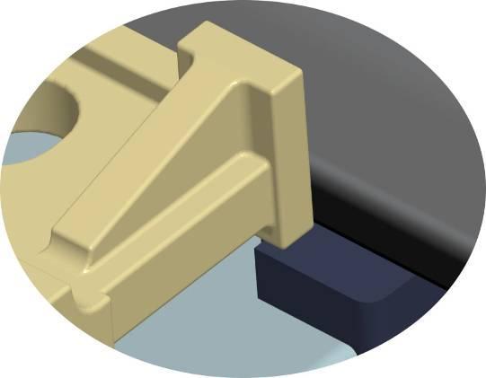
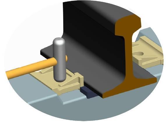
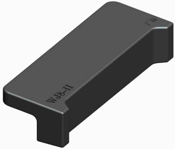
82 Assembly and laying of WJ-8 type fasteners 1 WJ-8 type fastener component composition and description WJ-8 type fasteners (hereinafter referred to as fasteners) are composed of screwl spikes, flat washers, spring bars, insulating blocks, gauge baffles, under-rail pads, iron pads, elastic pads under the iron pads and dowels. In addition, in order to adjust the height and position of the steel rail, it also includes a fine adjustment pad under the rail and a height-adjusting pad under iron pads.

83 insulator screw spike rubber pad spring clip baffle plate elastic pad under iron tie plates flat washer fine-tuning pad iron tie plate dowel height-adjusting pad under iron tie plates
84 1.1 Spring bars and under-rail pads There are two types of spring bars, namely the W1 type used in general sections and the X2 type that may be used on the bridge. The diameter of the W1 spring bar is 14 mm, and the diameter of the X2 spring bar is 13 mm. There are two types of under-rail pads: rubber pads used in general sections and composite pads that may be used on bridges. When it is necessary to reduce the line resistance on the bridge, X2 elastic strips can be used with composite backing plates. At this time, the longitudinal resistance of the rails of each group of fasteners is 4 kn.


85 φ14mm + W1 spring clip rubber pad φ13mm + X2 spring clip composite pad


86 1.2 Gauge baffle There are two types of gauge baffles: WJ8 gauge baffles for general sections and WJ8 joint gauge baffles for rail joints. WJ8 gauge baffles for general sections are divided into eleven specifications of 2#, 3#, 4#, 5#, 6#, 7#, 8#, 9#, 10#, 11#, 12#. 7# gauge baffle is used for standard rails, among which three specifications of 10#, 11#, 12# can be used at the rail joints. n different distance m, n corresponds to different number m Take 7# as an example to illustrate the product identification

87 WJ8 joint gauge baffles are divided into eight specifications, 2#, 3#, 4#, 5#, 6#, 7#, 8#, 9#, and 7# is used for standard gauge. 1.3 Inuslator Take 7# as an example to illustrate the product identification There are two types of insulators: Type I and Type II. Generally, type I is used for sections, and type II insulators are used for rail joints. d


88 I-type insulator mark II- type insulator mark

89 1.4 Elastic pad under iron tie plate The elastic tie plate under the iron tie plate is divided into two types: A and B. A Elastic pads are used for passenger dedicated lines that take into account freight; B Elastic pads are used for passenger dedicated lines. 1.5 Screw Spike There are two types of spiral spikes: S2 and S3. S2 is used when the height of the rail is less than 15 mm, and S3 is used when the height of the rail is greater than 15 mm. 101mm S2 screw spike S3 screw spike 116mm


 to prevent rainwater and mud")
90 1.6 The dowel is covered with plastic (or other materials) to prevent rainwater and mud from entering The component is embedded in the sleeper or track slab in advance, and the embedding accuracy should meet the requirements, and the top surface of the dowel should be flush with the bearing surface of the sleeper or track slab. After the dowel is buried, it should be covered with a plastic (or other material) cover to prevent rainwater and mud from entering. Cover with plastic (or other materials) to prevent rainwater and mud from entering


91 1.7 Height-adjusting pad The height-adjusting pad is divided into two types: the under-rail pad and the iron-tie plate, and between the elastic pad under iron tie plate with the sleeper or the rail bearing surface of the rail plate. The under-rail fine-tuning tie plate is divided into four specifications according to the thickness of 1 mm, 2mm, 5 mm and 8mm; the iron tie plate is divided into two specifications according to the thickness of 10 mm and 20 mm, and height-adjusting pad under the iron tie plate should be used as a pair. d 1mm 2mm 5mm 8mm height-adjusting pad under rail d 10mm 20mm height-adjusting pad under iron tie p late
92 2 Fastener laying sequence and requirements 2.1 Preparations before installation According to 1.1, select and prepare suitable types of spring clips (type W1 or X2) and suitable types of under-rail pads (rubber pads or composite pads). At the same time, properly prepare under-rail fine-tuning pads with thicknesses of 1 mm and 2 mm Prepare Type I insulating block and properly prepare Type II insulating block for use in rail joints Select and prepare 7# gauge baffles, and appropriately prepare 6# and 8# gauge baffles and joint gauge baffles of the same model Select and prepare the elastic tie plate (type A or B) under the iron tie plate according to Select and prepare S2 screw spikes.


93 2.1.6 Remove the mud from the sleeper or the bearing surface of the track slab and the bottom of the rail. Remove silt and debris from sleepers Remove mud from the bottom of the rail Remove the plastic (or other material) cover on the dowel.


94 2.2 Installation sequence in normal installation state Step 1: Place the elastic tie plate under the iron tie plate Lay an elastic tie plate under the iron tie plate at the middle position of the rail support to align the tie plate hole with the dowel hole.


95 Step 2: Place the iron tie plate. The bolt hole center of the iron tie plate should be aligned with the center of the rail dowel.


96 Step 3: Place the rail pad in the middle of the tie plate, and the flange of the rail pad should buckle the tie plate.

97 Step 4: Install a gauge baffle of appropriate specifications according to Table 1. The arc boss of the gauge baffle should be placed in the groove of the sleeper or the bottom of the rail groove of the track plate. Standard Gauge 1435mm+Gauge Adjustment n n n n m m a b c d m m
98 Table 1 Gauge adjustment (mm) Left Rail Right Rail Outer gauge baffle Inner gauge baffle Inner gauge baffle Outer gauge baffle
99

100 Note: When installing the gauge baffle, do not violently knock the gauge baffle into place. After putting it in place, pay attention to the gap between it and the sleeper or track plate, and the two front supports should be closely attached to the supporting rail surface. Step 5: Laying the rails.


101 Step 6: Place the insulators. Note: When placing the insulating block, do not knock it into place.


102 Step 7: Place the spring clip.
103 Step 8: Cover the screw spike with a flat washer and coat the threaded part with railway-specific protective grease, then screw it into the sleeve and tighten the elastic clip. The fastening of the elastic clip shall be based on the contact of the lower jaw of the front end of the elastic clip with the insulator. 1 2 screw spikes flat washer The threaded part is coated with railway special protective grease
104 3 Nut torque: Tightening torque of W1 spring clip is about 160 N m Tightening torque of X2 spring clip is about 110 N m tighten tighten


105 The lower jaw of the front end of the spring clip is in contact with the insulator lower jaw in the middle of the spring clip Special note: WJ8 joint gauge baffle and type II insulators should be used at the rail joint.

106 2.3 Installation adjustment Check the gauge and track direction. If there is any problem, you should replace the gauge baffle with a different number according to Table Check the empty hoisting, height and level of the rails. If there is any problem, please refer to Table 2 to put in an appropriate thickness adjustment pad. Special reminder: The under-rail fine-tuning pad shall not be placed on the under-rail pad, and the total thickness of the pad shall not be greater than 10 mm, and the total shall not exceed two pieces.


107 Table 2 Rail height adjustment unit:mm Fine-tuning the total thickness of the tie plate under the rail Lower the thickness of the iron tie plate ~ 10 1 ~ ~ 20 1 ~ ~ 30 1 ~ Put in the fine-tuning pad under the rail

108 放入垫板的总厚不得大于 10 mm, 总数不超过两块
109 2.4 Maintenance requirements At the early stage of operation, attention should be paid to observe the use of fasteners. If the fasteners are loosened due to the residual compression of the elastic tie plate under the iron tie plate, they should be re-tightened in time. When it is found that the rail is empty and the height is uneven, the height adjustment pad should be inserted in time. When the height of the rail relative to the normal state is greater than 15 mm, the S3 spiral spike should be used. Put in the iron tie plate to raise the baffle plate. Special reminder: Each pair of iron tie plate is composed of two pieces, which are inserted from the side. The iron tie plate can only be used in a single pair, not stacked. When the height of the rail relative to the normal state is greater than 15 mm, the S3 screw spike should be used.
110 Put in the iron tie plate to raise the baffle plate When the height of the rail relative to the normal state is greater than 15 mm, the S3 screw spike should be used.

111 The irontie plate can only be used in a single pair, not stacked If the fastener parts are found to be damaged during use, they should be replaced in time When it is necessary to remove the screw spikes, avoid mud and dirt from entering the rail dowels.
112 Thank You!

113 Company: ANYANG RAILWAY EQUIPMENT CO., LTD Address: Simenquan Village, Longquan Town, Longan District, Anyang City, Henan Province, China Contact Person: Ms. Xu Yanli Mobile Phone: WhatsApp: WeChat: Yanli81 Website: Facebook: Linkedin: Twitter: