Verification of Welded eaves moment connection of open sections
|
|
|
- Dennis Williams
- 6 years ago
- Views:
Transcription
1 Verification of Welded eaves moment connection of open sections Ing. Lukáš Gödrich June Description The objective of this study: verification of CBFEM IDEARS software with component method. Description of verified connection: welded moment frame, horizontal beam is welded on the column flange, column stiffened with two horizontal stiffeners in levels of the beam flanges. Compressed parts are designed as maximal 3 rd class to avoid stability problems (horizontal stiffeners of column, web panel in shear or compression, compressed beam flange). Horizontal beam is considered as both sides fixed beam of length 6m loaded by continuous load over the entire length=>vertical shear force and bending moment in the plane are of the same absolute values. 2 Analytical model Component method Six components is examined: fillet weld, web panel in shear, column web in transverse compression, column web in transverse tension, column flange in bending and beam flange in compression. All components designed according to EN Design loads of component depend on the position: Web panel in shear design loads on the vertical axis of the column Other components- reduced design loads in column flange to which is connected horizontal beam. 3.1 Fillet weld The weld is closed around a cross-section of the beam. The thickness of the weld on the flanges can differ from the thickness of the weld on the web. Vertical shear force is transferred only by welds on the web and plastic stress distribution is considered. Bending moment is transferred by whole weld shape and elastic stress distribution is considered. Effective weld width depending on the horizontal stiffness of the column is considered (because of bending of the column flange). Design of the weld is done according to EN (6). The assessment is carried out in two major points: on the upper or lower edge of the flange (maximum bending stress) and in the crossing of the flange and the web (combination of shear force and bending moment stresses). 1
2 3.2 Web panel in shear The thickness of the column web is designed to be maximally third class to avoid stability problem see EN (1). Two contributions to the load capacity are considered: resistance of the column wall in shear and the contribution from the frame behaviour of the column flanges and horizontal stiffeners see EN (6.7 and 6.8). 3.3 Column web in transverse compression Effect of the interaction of the shear load is considered see EN (tab. 6.3). Influence of longitudinal stress in the wall of the column is considered see EN (2). Horizontal stiffeners prevent from stability problem The horizontal stiffeners are included in the load capacity of this component with the effective area. 3.4 Column web in transverse tension Effect of the interaction of the shear load is considered see EN (tab. 6.3). The horizontal stiffeners are included in the load capacity of this component with the effective area. 3.5 Column flange in bending Horizontal stiffeners brace column flange, this component is not considered. 3.6 Beam flange in compression The horizontal beam is designed to be maximally third class to avoid stability problem. 2
3 For better understanding of the component method design of the beam IPE330 to column HEB260 connection is shown below 3
4 4
5 5
6 6

7 4 Results by CBFEM Idea RS software CBFEM - combination of the advantages of finite element method and analytical component method. Shell elements, special spring and contact elements with characteristics according to the component method. Elastic-plastic stress-strain diagram for material of shell elements. Assessment is based on the maximum strain given according to EN by value of 5%. Bolts are modelled using special spring elements and assessment is carried out according to standard procedures described in EN Result of Idea RS software for the beam IPE330 to column HEB260 connection is shown below. 7
8 5 Global behaviour and verification Comparison of the global behaviour of the joint described by moment-rotation diagrams for both design procedures mentioned above was done. Attention was focused on the main characteristics of the moment-rotation diagram: initial stiffness, elastic resistance and design resistance. Connection of the beam IPE330 to column HEB260 was chosen as a sample. Joint with horizontal stiffeners in column is considered according to component method as a rigid joint with S j,ini =. For this reason, a joint without horizontal stiffeners in column is used for this global behaviour study. Results of both design procedures are shown in the graph and the table below. Both procedures give for initial 8
9 Moment [knm] stiffness, elastic resistance and design resistance similar results. In addition, maximal rotation is compared. Component method gives for maximal rotation only guaranteed minimal value 15 mrad see EN (2) and that is the reason of much lower value compared to CBFEM CBFEM Component method Rotation [mrad] CM CBFEM CM/CBFEM Initial stiffness [knm/rad] Elastic resistance [knm] Design resistance [knm] Maximal rotation [mrad] Verification of resistance Design resistance calculated by CBFEM Idea RS software were compared with the results of the component method in the next step. The comparison was focused on capacity and also to determine the critical component. The study was performed for three different parameters: beam cross-section, column cross section and thickness of the column wall. In the first case with parameter beam cross-section was a column cross-section HEB260 and horizontal column stiffener thick was 10 mm and width corresponding to the width of beam flange. IPE sections were selected for horizontal beam from IPE140 to IPE500. The results are shown in table and graph. 9
10 Design resistance My/Vz [knm / kn] Parameter Resistance [kn/knm] Component method Critical component Resistance [kn/knm] CBFEM-Idea RS Critical component IPE Beam flange in compression 27 Beam flange in compression IPE Beam flange in compression 34 Beam flange in compression IPE Beam flange in compression 48 Beam flange in compression IPE Beam flange in compression 67 Beam flange in compression IPE Beam flange in compression 80 Beam flange in compression IPE Beam flange in compression 103 Beam flange in compression IPE Beam flange in compression 125 Beam flange in compression IPE Web panel in shear 142 Beam flange in compression IPE Web panel in shear 154 Beam flange in compression IPE Web panel in shear 167 Web panel in shear IPE Web panel in shear 183 Web panel in shear IPE Web panel in shear 202 Web panel in shear IPE Web panel in shear 223 Web panel in shear CM-beam flange in compression CM-web panel in shear CBFEM-beam flange in compression CBFEM-web panel in shear Size of IPE profile of the beam In the second case with parameter column cross-section was a beam cross-section IPE 330 and horizontal column stiffener thick was 10 mm and width 160 mm. HEA and HEB cross-sections were selected for horizontal beam from HEA 160 to HEA 500 and from HEB 160 to HEB 500. The results are shown in table and graphs. 10
11 Parameter Resistance [kn/knm] Component method Critical component Resistance [kn/knm] CBFEM-Idea RS Critical component HEA Web panel in shear 50 Web panel in shear HEA Web panel in shear 59 Web panel in shear HEA Web panel in shear 74 Web panel in shear HEA Web panel in shear 83 Web panel in shear HEA Web panel in shear 104 Web panel in shear HEA Web panel in shear 117 Web panel in shear HEA Web panel in shear 127 Web panel in shear HEA Web panel in shear 152 Web panel in shear HEA Web panel in shear 168 Web panel in shear HEA Web panel in shear 195 Beam flange in compression HEA Web panel in shear 208 Beam flange in compression HEA Beam flange in compression 245 Beam flange in compression HEA Beam flange in compression 256 Beam flange in compression HEA Beam flange in compression 264 Beam flange in compression HEB Web panel in shear 70 Web panel in shear HEB Web panel in shear 88 Web panel in shear HEB Web panel in shear 101 Web panel in shear HEB Web panel in shear 124 Web panel in shear HEB Web panel in shear 139 Web panel in shear HEB Web panel in shear 154 Web panel in shear HEB Web panel in shear 179 Beam flange in compression HEB Web panel in shear 196 Beam flange in compression HEB Web panel in shear 226 Beam flange in compression HEB Beam flange in compression 240 Beam flange in compression HEB Beam flange in compression 245 Beam flange in compression HEB Beam flange in compression 251 Beam flange in compression HEB Beam flange in compression 258 Beam flange in compression HEB Beam flange in compression 266 Beam flange in compression 11
12 Design resistance My/Vz [knm / kn] Design resistance My/Vz [knm / kn] CM-beam flange in compression CM-web panel in shear 50 CBFEM-beam flange in compression CBFEM-web panel in shear Size of HEA profile of the column CBFEM-web panel in shear Size of HEB profile of the column CM-beam flange in compression CM-web panel in shear CBFEM-beam flange in compression In the third case with parameter thickness of the column wall was a beam cross-section IPE 330 and column cross-section dimensions corresponded to HEA 320 except the wall thickness. Horizontal column stiffener thick was 10 mm and width 160 mm. The wall thickness was chosen from 4 mm to 16 mm with increments of 1 mm. The results are shown in table and graph. 12
13 Design resistance My/Vz [knm / kn] Parameter Resistance [kn/knm] Component method Critical component Resistance [kn/knm] CBFEM-Idea RS Resistance [kn/knm] 4 82 Web panel in shear 99 Web panel in shear 5 94 Web panel in shear 115 Web panel in shear Web panel in shear 131 Web panel in shear Web panel in shear 147 Web panel in shear Web panel in shear 162 Web panel in shear Web panel in shear 177 Web panel in shear Web panel in shear 190 Beam flange in compression Web panel in shear 203 Beam flange in compression Web panel in shear 216 Beam flange in compression Web panel in shear 227 Beam flange in compression Web panel in shear 236 Beam flange in compression Beam flange in compression 240 Beam flange in compression Beam flange in compression 241 Beam flange in compression CM-beam flange in compression CM-web panel in shear CBFEM-beam flange in compression CBFEM-web panel in shear Thickness of the column web To illustrate the accuracy of the CBFEM model, results of the parametric studies were summarized in graph comparing resistance by CBFEM and component method. The results show that the difference of the two calculation methods is up to 5%, which is a generally acceptable value. Except the study with wall thickness parameter where CBFEM model gives higher resistance compared to component method. This difference is caused by considering welded cross-sections. For welded cross-section is in component method for transfer of shear load considered only web and contribution of the flanges is neglected. 13
14 CBFEM-Design resistance - My/Vz [knm/kn] Parameter-Size of the beam Parameter-Size of the column HEA Parameter-Size of the column HEB Parameter-Thickness of the column web CBFEM=CM CBFEM=1,05 CM CBFEM=0,95 CM CM-Design resistance - My/Vz [knm/kn] 7 Reliability Reliability of CBFEM software is provided in accordance with the strategy of EC considering partial safety factors. Inputs of internal loads are entered as design values with the load factor and combination coefficient. Material safety factors according to EN are used for design resistance of the connection. For bolts and welds M =1,25 and for plates M =1,0. 8 Résumé Verification studies confirmed the accuracy of the CBFEM IDEA RS software. Results of this software were compared with the results of the component method recommended in EN Both procedures predict similar global behaviour of the joint. Except the study with web thickness parameter is the difference in design resistance of the two calculation methods up to 5%, which is a generally acceptable value. Higher resistance by CBFEM IDEA RS software compared to component method for study with web thickness parameter is caused by conservative calculation of component method for welded cross-sections. Reliability of CBFEM software is provided in accordance with the strategy of EC considering partial safety factors. 14


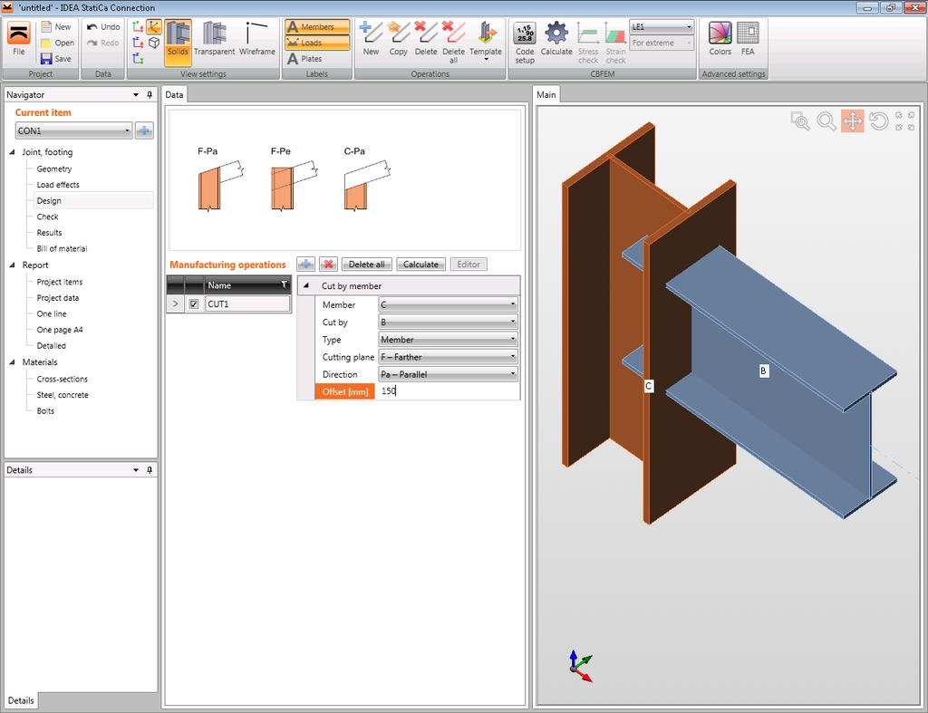
15 9 Benchmark example Choise of the geometry: 15

16 Setting of the material: Setting of the cross-sections: 16

17 Cutting of the profiles, setting of the welds: 17

18 18
19 Adding of the horizontal stiffeners of column: 19

20 Setting of the loads: 20

21 Setting of the calculation: 21

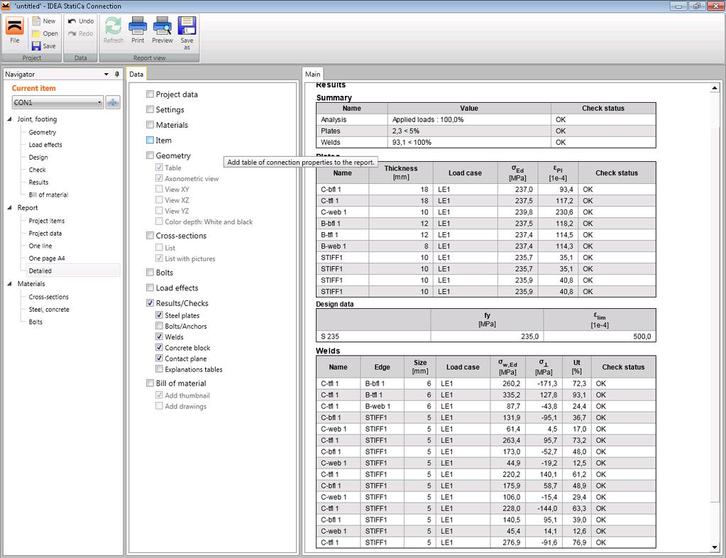
22 Results: 22
STRUCTURAL ANALYSIS AND DESIGN OF STEEL CONNECTIONS USING CBFEM METHOD
 Journal of Civil Engineering and Architecture STRUCTURAL ANALYSIS AND DESIGN OF STEEL CONNECTIONS USING CBFEM METHOD Lubomír Šabatka *, Jaromír Kabeláč **, Drahoslav Kolaja *, Martin Pospíšil * * IDEA
Scientific Seminar Design of Steel and Timber Structures SPbU, May 21, 2015
 Riga Technical University Institute of Structural Engineering and Reconstruction Scientific Seminar The research leading to these results has received the funding from Latvia state research programme under
UNIVERSITY OF BOLTON WESTERN INTERNATIONAL CENTRE FZE. BEng (HONS) CIVIL ENGINEERING SEMESTER ONE EXAMINATION 2015/2016
 CIVIL ENGINEERING SEMESTER ONE EXAMINATION 2015/2016") OCD59 UNIVERSITY OF BOLTON WESTERN INTERNATIONAL CENTRE FZE BEng (HONS) CIVIL ENGINEERING SEMESTER ONE EXAMINATION 2015/2016 ADVANCED STRUCTURAL ANALYSIS AND DESIGN MODULE NO: CIE6001 Date: Tuesday 12
OCD59 UNIVERSITY OF BOLTON WESTERN INTERNATIONAL CENTRE FZE BEng (HONS) CIVIL ENGINEERING SEMESTER ONE EXAMINATION 2015/2016 ADVANCED STRUCTURAL ANALYSIS AND DESIGN MODULE NO: CIE6001 Date: Tuesday 12
RELIABILITY OF SEISMIC LINKS IN ECCENTRICALLY BRACED STEEL FRAMES
 RELIABILITY OF SEISMIC LINKS IN ECCENTRICALLY BRACED STEEL FRAMES ABSTRACT : M. Čaušević 1, M. Bulić, B. Androić 3 1 Professor, University of Rijeka, Faculty of Civil Engineering, Rijeka, Croatia Assistant,
Types Of Roofs - Vault
 1 Types Of Roofs - Vault Implementation Of the Concrete On Vault Implementation Of Vault Earthquake Damage 2 Types Of Roofs - Joist And Block 3 Types Of Coverage Roofs-Composite 4 5 Building Structure
The semi-rigid behaviour of column bases influences the structural frame response and in particular:
 Ligações Semi-Rígidas Placa de Base Programa de Pós-Graduação em Engenharia Civil PGECIV - Mestrado Acadêmico Faculdade de Engenharia FEN/UERJ Disciplina: Projeto Estrutural I Professor: Luciano Rodrigues
Design Methods of Elements from Cross-Laminated Timber Subjected to Flexure
 RIGA TECHNICAL UNIVERSITY INSTITUTE OF STRUCTURAL ENGINEERING AND RECONSTRUCTION A.Vilguts, D.Serdjuks, L.Pakrastins Design Methods of Elements from Cross-Laminated Timber Subjected to Flexure RIGA 2015
Modelling of RC moment resisting frames with precast-prestressed flooring system
 Modelling of RC moment resisting frames with precast-prestressed flooring system B.H.H. Peng, R.P. Dhakal, R.C. Fenwick & A.J. Carr Department of Civil Engineering, University of Canterbury, Christchurch.
HIERARCHICAL VALIDATION OF FEM MODELS
 Krzysztof OSTROWSKI 1 Aleksander KOZŁOWSKI 2 HIERARCHICAL VALIDATION OF FEM MODELS In article are presented results from multistage hierarchical validation of the advanced FEM models used to define rotation
On Improved Performance Of Eccentrically Braced Frames With Replaceable Shear Link
 On Improved Performance Of Eccentrically Braced Frames With Replaceable Shear Link M. Moestopo Faculty of Civil and Environmental Engineering, Institut Teknologi Bandung, Indonesia. A. Novan Faculty of
Seismic isolation for three buildings in Nicosia
 Earthquake Resistant Engineering Structures VII 315 Seismic isolation for three buildings in Nicosia K. Yiannouris 1 & G. C. Giuliani 2 1 Marathefitis-Yiannouris Architects Engineers, Nicosia Cyprus 2
Analysis of Shear Wall Transfer Beam Structure LEI KA HOU
 Analysis of Shear Wall Transfer Beam Structure by LEI KA HOU Final Year Project report submitted in partial fulfillment of the requirement of the Degree of Bachelor of Science in Civil Engineering 2013-2014
An example of finite element modelling of progressive collapse
 COST Action TU0601 Robustness of Structures 2nd and 3rd of March 2009 Coimbra, Portugal An example of finite element modelling of progressive collapse Leslaw KWASNIEWSKI Marian A. GIZEJOWSKI Faculty of
Overview of Presentation. SCBFs are Conceptually Truss Structures
 Ultimate Strength and Inelastic Behavior of Braced Frame Gusset Plate Connections Charles W. Roeder University of Washington Department of Civil and Environmental Engineering Seattle, WA 98195 Structural
Renovation of Buildings using Steel Technologies (ROBUST)
") Renovation of Buildings using Steel Technologies (ROBUST) RFCS Project RFSR-CT-2007-0043 WP 4.2 Renovation of roofs using open trusses in light steel C sections Date: 2009 Author: Mark Lawson SCI, Silwood
Renovation of Buildings using Steel Technologies (ROBUST) RFCS Project RFSR-CT-2007-0043 WP 4.2 Renovation of roofs using open trusses in light steel C sections Date: 2009 Author: Mark Lawson SCI, Silwood
Structural Design of Pergola with Airfoil Louvers
 International Journal of Advanced Structures and Geotechnical Engineering ISSN 2319-5347, Vol. 04, No. 03, July 2015 Structural Design of Pergola with Airfoil Louvers MUHAMMAD TAYYAB NAQASH Aluminium TechnologyAauxiliary
Behaviour and design of innovative hybrid coupled shear walls for steel buildings in seismic areas
 Behaviour and design of innovative hybrid coupled shear walls for steel buildings in seismic areas A. Zona, G. Leoni & A. Dall Asta University of Camerino, Italy C. Braham, T. Bogdan & H. Degée University
Steel Connection Design
 Chapter Steel Connection Design The steel connection design modules can be used for design of common welded and bolted steel connection. Steel Connection Design 5-1 Quick Reference Steel Connection Design
Nonlinear Finite Element Modeling & Simulation
 Full-Scale Structural and Nonstructural Building System Performance during Earthquakes & Post-Earthquake Fire A Joint Venture between Academe, Industry and Government Nonlinear Finite Element Modeling
DESIGN OF WALLS FOR SHEAR
 mortarless masonry Design Manual Part 3 (IS 456:2000) Section 5 Page: 1 SECTION 5. DESIGN OF WALLS FOR SHEAR Shear walls: Load-bearing walls are mostly designed to carry axial compression loads, however
Strength Study on Castellated Beam
 Strength Study on Castellated Beam 1 B. Anupriya 2 Dr. K. Jagadeesan 1 Assistant Professor Department of Civil Engineering Arasu Engineering College, Kumbakonam, Tamilnadu, India 2 Professor Department
Council on Tall Buildings
 Structure Design of Sino Steel (Tianjin) International Plaza Xueyi Fu, Group Chief Engineer, China Construction Design International 1 1 Brief of Project 2 Location: Tianjin Xiangluowan Business District
Displacement Based Assessment and Improvement of a Typical New Zealand Building by an Average Engineer
 Displacement Based Assessment and Improvement of a Typical New Zealand Building by an Average Engineer M.L. Grant LGE Consulting, Masterton 2016 NZSEE Conference ABSTRACT: The Radiohouse building is a
PORTAL FRAMES 1.0 INTRODUCTION
 36 PORTAL FRAMES 1.0 INTRODUCTION The basic structural form of portal frames was developed during the Second World War, driven by the need to achieve the low - cost building envelope. Now they are the
SEISMIC BEHAVIOR OF STEEL RIGID FRAME WITH IMPERFECT BRACE MEMBERS
 INTERNATIONAL JOURNAL OF CIVIL ENGINEERING AND TECHNOLOGY (IJCIET) International Journal of Civil Engineering and Technology (IJCIET), ISSN 976 638 (Print), ISSN 976 6316(Online), Volume 6, Issue 1, January
Advance Design Bracing members design according to Eurocode 3
 Advance Design Bracing members design according to Eurocode 3 Author: Eng. Victor Seiculescu, PhD student Advance Design was specifically developed for industry professionals that require a superior solution
STUDY ON MODELING OF STEEL RIGID FRAME BRIDGE FOR DYNAMIC ELASTO-PLASTIC ANALYSIS
 STUDY ON MODELING OF STEEL RIGID FRAME BRIDGE FOR DYNAMIC ELASTO-PLASTIC ANALYSIS 83 Tsutomu YOSHIZAWA 1, Masaru NARITOMI 2, Osamu ISHIBASHI 3 And Masahide KAWAKAMI 4 SUMMARY The modeling method of the
DESIGN OF STEEL FRAMES OF DISSIPATIVE SHEAR WALLS
 SDSS Rio 21 STABILITY AND DUCTILITY OF STEEL STRUCTURES E. Batista, P. Vellasco, L. de Lima (Eds.) Rio de Janeiro, Brazil, September 8-1, 21 DESIGN OF STEEL FRAMES OF DISSIPATIVE SHEAR WALLS C. Neagu*,
Torsion in tridimensional composite truss bridge decks
 Torsion in tridimensional composite truss bridge decks André B. Almeida Instituto Superior Técnico Technical University of Lisbon Lisbon, Portugal e-mail: branco.almeida.a@gmail.com Abstract Torsion stiffness
Chapter. Masonry Design
 Chapter Masonry Design The masonry design section contains modules for the analysis of reinforced masonry beams subjected to pure bending and unreinforced masonry walls subjected to axial compression and
Eurocode 9: Design of aluminium structures
 BRITISH STANDARD BS EN 1999-1-1:2007 +A1:2009 Eurocode 9: Design of aluminium structures Part 1-1: General structural rules ICS 77.150.10; 91.010.30; 91.080.10 National foreword This British Standard was
Design of large scale wind turbine towers in seismic areas
 Design of large scale wind turbine towers in seismic areas C.C. Baniotopoulos, I. Lavassas, G. Nikolaidis, P.Zervas Institute of Metal Structures, Dept. of Civil Engineering, A.U.Th., Thessaloniki, Greece
THE EXTENDED N2 METHOD IN SEISMIC DESIGN OF STEEL FRAMES CONSIDERING SEMI-RIGID JOINTS
 THE EXTENDED N2 METHOD IN SEISMIC DESIGN OF STEEL FRAMES CONSIDERING SEMI-RIGID JOINTS Paulina KROLO 1, Mehmed CAUSEVIC 2 and Mladen BULIC 3 ABSTRACT In this paper the nonlinear static seismic analysis
INTERNATIONAL JOURNAL OF CIVIL AND STRUCTURAL ENGINEERING Volume 2, No 2, 2011
 INTERNATIONAL JOURNAL OF CIVIL AND STRUCTURAL ENGINEERING Volume 2, No 2, 2011 Copyright 2010 All rights reserved Integrated Publishing services Research article ISSN 0976 4399 Nonlinear Seismic Behavior
CYCLIC TESTING OF BOLTED CONTINUOUS I-BEAM-TO-HOLLOW SECTION COLUMN CONNECTIONS
 10NCEE Tenth U.S. National Conference on Earthquake Engineering Frontiers of Earthquake Engineering July 21-25, 2014 Anchorage, Alaska CYCLIC TESTING OF BOLTED CONTINUOUS I-BEAM-TO-HOLLOW SECTION COLUMN
THE STRUCTURAL BEHAVIOUR OF COMPOSITE CONNECTIONS WITH STEEL BEAMS AND PRECAST HOLLOW CORE SLABS
 Advanced Steel Construction Vol. 5, No. 1, pp. 96-105 (2009) 96 THE STRUCTURAL BEHAVIOUR OF COMPOSITE CONNECTIONS WITH STEEL BEAMS AND PRECAST HOLLOW CORE SLABS Feng Fu Structural Engineer, WSP Group,
Refined Plastic Hinge Analysis of Steel Frame Structures Comprising Non-Compact Sections II: Verification
 Refined Plastic Hinge Analysis of Steel Frame Structures Comprising Non-Compact Sections II: Verification P. Avery and M. Mahendran Physical Infrastructure Centre, School of Civil Engineering, Queensland
The Behaviour of Beam-Column Elements with Variable I Cross-Sections considering Lateral Restraints
 Paper 3 Civil-Comp Press, 2012 Proceedings of the Eleventh International Conference on Computational Structures Technology, B.H.V. Topping, (Editor), Civil-Comp Press, Stirlingshire, Scotland The Behaviour
Sabah Shawkat Cabinet of Structural Engineering 2017
 3.1-1 Continuous beams Every building, whether it is large or small, must have a structural system capable of carrying all kinds of loads - vertical, horizontal, temperature, etc. In principle, the entire
Journal of Asian Scientific Research EVALUATION OF RECTANGULAR CONCRETE-FILLED STEEL-HOLLOW SECTION BEAM-COLUMNS
 Journal of Asian Scientific Research journal homepage: http://www.aessweb.com/journals/5003 EVALUATION OF RECTANGULAR CONCRETE-FILLED STEEL-HOLLOW SECTION BEAM-COLUMNS Kamyar Bagherinejad 1 ---- Emad Hosseinpour
13 GOOD AND BAD DETAILING
 1 OOD AND AD DETAILIN Many different detailing solutions can be used to connect one steel member to another. Furthermore, the differences in custom and practise between European countries, differences
Introduction to Structural Analysis TYPES OF STRUCTURES LOADS AND
 AND Introduction to Structural Analysis TYPES OF STRUCTURES LOADS INTRODUCTION What is the role of structural analysis in structural engineering projects? Structural engineering is the science and art
AISI S E1 AISI STANDARD. Errata to North American Specification. for the Design of Cold-Formed. Steel Structural Members.
 AISI S100-12-E1 AISI STANDARD Errata to North American Specification for the Design of Cold-Formed Steel Structural Members 2012 Edition Amendment on August 16, 2013 Errata to North American Specification
Idealization of Structures and Loads
 Idealization of Structures and Loads To analyze a structure by the methods that are described in these notes it must be idealized. By utilizing the idealized structural model the deformations and internal
ANALYTICAL AND EXPERIMENTAL STUDIES ON SEISMIC BEHAVIOR OF DEEP COLUMN-TO-BEAM WELDED REDUCED BEAM SECTION MOMENT CONNECTIONS
 13 th World Conference on Earthquake Engineering Vancouver, B.C., Canada August 1-6, 24 Paper No. 1599 ANALYTICAL AND EXPERIMENTAL STUDIES ON SEISMIC BEHAVIOR OF DEEP COLUMN-TO-BEAM WELDED REDUCED BEAM
Seismic assessment of horizontal cylindrical reservoirs
 Seismic assessment of horizontal cylindrical reservoirs Christos Baltas 1, Pierino Lestuzzi 1, 2, Martin G. Koller 1 1 2 Résonance Ingénieurs-Conseils SA 21 rue Jacques Grosselin, 1227 Carouge, Suisse
Design of Steel Structures Prof. S.R.Satish Kumar and Prof. A.R.Santha Kumar
 2.6 Portal frames Portal frames are the most commonly used structural forms for single-storey industrial structures. They are constructed mainly using hot-rolled sections, supporting the roofing and side
BRACING REQUIREMENTS FOR LATERAL STABILITY
 BRACING REQUIREMENTS FOR LATERAL STABILITY By John J. Zahn, 1 M. ASCE ABSTRACT: The forces induced in braces depend on the magnitude of initial imperfections (lateral bending and twist) and magnitude of
Structural Design of a Containership Approximately 3100 TEU According to the Concept of General Ship Design B-178
 Structural Design of a Containership Approximately 3100 TEU According to the Concept of General Ship Design B-178 W.Souadji, Zbigniew Sekulski, B.Hamoudi 1 Abstract The design developed in this work is
Analysis and design of steel beam-to-column web connections, Ph.D. dissertation, August 1979
 Lehigh University Lehigh Preserve Fritz Laboratory Reports Civil and Environmental Engineering 1979 Analysis and design of steel beam-to-column web connections, Ph.D. dissertation, August 1979 Glenn P.
Page 53 pren (Final draft)
") Page 53 SECTION 5 STRUCTURAL ANALYSIS 5.1 General provisions The purpose of analysis is to establish the distribution of either internal forces and moments, or stresses, strains and displacements, over
Page 53 SECTION 5 STRUCTURAL ANALYSIS 5.1 General provisions The purpose of analysis is to establish the distribution of either internal forces and moments, or stresses, strains and displacements, over
Non Linear Analysis of Composite Beam Slab Junction with Shear Connectors using Ansys.16
 International Journal of Engineering Science Invention ISSN (Online): 2319 6734, ISSN (Print): 2319 6726 Volume 5 Issue 4 April 2016 PP.22-29 Non Linear Analysis of Composite Beam Slab Junction with Shear
22. DESIGN OF STEEL BRACED FRAMES Eccentrically Braced Steel Frames
 22. DESIGN OF STEEL BRACED FRAMES 22.1 Eccentrically Braced Steel Frames Objective is to dissipate energy in the shear or moment links and to protect the remainder of the frame from inelastic action, including
THE BRACE CONNECTION THE BOLTED OPTION FIGURE 1 MODEL SHOWING THE BOILER AND THE STRUCTURAL SUPPORT SYSTEM (BOILER BUILDING)
") Comparative Study of Bolted versus Welded SCBF Connections Authors: Robert P. Krumpen III P.E., Bechtel Corporation, rpkrumpe@bechtel.com Dr. Peter J. Carrato P.E. S.E., Bechtel Corporation, pcarrato@bechtel.com
Comparative Study of Bolted versus Welded SCBF Connections Authors: Robert P. Krumpen III P.E., Bechtel Corporation, rpkrumpe@bechtel.com Dr. Peter J. Carrato P.E. S.E., Bechtel Corporation, pcarrato@bechtel.com
FE Review Mechanics of Materials
 1 2 3 4 5 6 7 8 9 10 11 12 13 14 15 16 17 18 19 20 21 22 23 24 25 26 27 28 29 1. T he element is subjected to the plane stress condition shown. a-x = - 140 M Pa a- y = 205 M Pa Txy = 100 M Pa What is t
Local and Distortional Buckling of Cold-Formed Steel Members
 Local and Distortional Buckling of Cold-Formed Steel Members André Eduardo Martins Rua Pinto MSc Dissertation in Civil Engineering Civil Engineering and Architecture Department, Instituto Superior Técnico,
FEM STRESS CONCENTRATION FACTORS FOR FILLET WELDED CHS-PLATE T-JOINT
 Engineering Review Vol. 32, Issue 3, 147-155, 2012. 147 FEM STRESS CONCENTRATION FACTORS FOR FILLET WELDED CHS-PLATE T-JOINT S. * G. Turkalj Department of Engineering Mechanics, Faculty of Engineering,
Cable bracing design in adaptable dual control systems
 Earthquake Resistant Engineering Structures IX 311 Cable bracing design in adaptable dual control systems M. C. Phocas & T. L. Sophocleous Department of Architecture, University of Cyprus, Nicosia, Cyprus
ESECMASE - SHEAR TEST METHOD FOR MASONRY WALLS WITH REALISTIC BOUNDARY CONDITIONS
 ESECMASE - SHEAR TEST METHOD FOR MASONRY WALLS WITH REALISTIC BOUNDARY CONDITIONS E. FEHLING Professor of Civil Engineering Institute of Structural Engineering Chair of Structural Concrete University of
Structural assessment of the integrated steel fly-overs widening the historic multiple-arch concrete viaduct over the Pede valley
 Structural assessment of the integrated steel fly-overs widening the historic multiple-arch concrete viaduct over the Pede valley Ken SCHOTTE PhD Student, Researcher Ken.Schotte@UGent.be Bart DE PAUW Researcher
Behavior and Analysis of Horizontally Curved Composite Steel Girder Bridge System
 e-issn: 2278-1684, p-issn: 232-334X. PP 45-52 Behavior and Analysis of Horizontally Curved Composite Steel Girder Bridge System Gourav Gajrani 1, Dr. L. M. Gupta 2 1,2 (Department of App. Mechanics, VNIT,
SEISMIC BEHAVIOUR OF RC BUILDING RESTING ON PLAIN AND SLOPING GROUND WITH BRACINGS AND SHEAR WALL
 SEISMIC BEHAVIOUR OF RC BUILDING RESTING ON PLAIN AND SLOPING GROUND WITH BRACINGS AND SHEAR WALL Yashaswini R 1, Dr. Mahesh Kumar G 2 1M.Tech Student, CAD Structures, Shridevi Institute of Engineering
CHAPTER 3 ANALYSIS METHOD
 CHAPTER 3 ANALYSIS METHOD 3.1 ELASTIC STATIC ANALYSIS Elastic static analysis is done to calculate stress ratio between before and after subsidence. The structure will behave elastic when the first yield
Jurnal Teknologi PERFORMANCE APPRAISAL OF STEEL CONNECTION IN LOW RISE BUILDINGS. Full Paper. H. F. Siuw, M. Taib *
 Jurnal Teknologi PERFORMANCE APPRAISAL OF STEEL CONNECTION IN LOW RISE BUILDINGS H. F. Siuw, M. Taib * Building Surveying Programme, School of Housing, Building and Planning, Universiti Sains Malaysia,
Flat Slabs. d 2. A typical flat slab (without drop and column head)
") 1 CHAPTER Flat Slabs 1.1 INTRDUCTIN Common practice of design and construction is to support the slabs by beams and support the beams by columns. This may be called as beam-slab construction. The beams
1 CHAPTER Flat Slabs 1.1 INTRDUCTIN Common practice of design and construction is to support the slabs by beams and support the beams by columns. This may be called as beam-slab construction. The beams
Interpretation of SECTION 12 DESIGN AND DETAILING FOR EARTHQUAKE LOADS IS
 Interpretation of SECTION 12 DESIGN AND DETAILING FOR EARTHQUAKE LOADS 12.1 General IS 800-2007 Steel frames shall be so designed and detailed as to give them adequate strength, stability and ductility
Jurnal Teknologi STEEL WEIGHT SAVING DEVELOPED FROM SEMI- CONTINUOUS CONSTRUCTION IN MULTI-STOREY BRACED STEEL FRAME BASED ON EURO-CODE 3.
 Jurnal Teknologi STEEL WEIGHT SAVING DEVELOPED FRO SEI- CONTINUOUS CONSTRUCTION IN ULTI-STOREY BRACED STEEL FRAE BASED ON EURO-CODE 3 T. Y. Taher a,.. Tahir a*, A. Sulaiman a, S. P. Ngian a, A. Saggaff
Structural Glossary. ARCH 631 Structural Glossary F2014abn
 Structural Glossary Allowable strength: Nominal strength divided by the safety factor. Allowable stress: Allowable strength divided by the appropriate section property, such as section modulus or cross
Example. Monday, October 19, 2015
 Example Monday, October 19, 2015 11:26 AM Using a prestressed Y4 beam with reinforced concrete deck slab as the deck example as shown in Fig.1; the deck having a 10 skew, a span of 20m and carrying a 7.3m
Fagà, Bianco, Bolognini, and Nascimbene 3rd fib International Congress
 COMPARISON BETWEEN NUMERICAL AND EXPERIMENTAL CYCLIC RESPONSE OF ALTERNATIVE COLUMN TO FOUNDATION CONNECTIONS OF REINFORCED CONCRETEC PRECAST STRUCTURES Ettore Fagà, Dr, EUCENTRE, Pavia, Italy Lorenzo
RE-CENTRING DUAL ECCENTRICALLY BRACED FRAMES WITH REMOVABLE LINKS
 THE PUBLISHING HOUSE PROCEEDINGS OF THE ROMANIAN ACADEMY, Series A, OF THE ROMANIAN ACADEMY Volume 17, Number 2/2016, pp. 169 177 RE-CENTRING DUAL ECCENTRICALLY BRACED FRAMES WITH REMOVABLE LINKS Adriana
NONLINEAR DYNAMIC RESPONSE OF DISSIPATIVE DEVICES FOR SEISMIC RESISTANT STEEL FRAMES: EXPERIMENTAL BEHAVIOUR AND NUMERICAL SIMULATION
 COMPDYN 211 III ECCOMAS Thematic Conference on Computational Methods in Structural Dynamics and Earthquake Engineering M. Papadrakakis, M. Fragiadakis, V. Plevris (eds.) Corfu, Greece, 25 28 May 211 NONLINEAR
PUNCHING RESEARCH AT UNIVERSIDADE NOVA DE LISBOA
 2011 PUNCHING RESEARCH AT UNIVERSIDADE NOVA DE LISBOA A. Ramos 1, V. Lúcio 2, D. Faria 3, M. Inácio 4 Abstract At the Civil Engineering Department of Universidade Nova de Lisboa punching research has been
SEISMIC EVALUATION OF HIGH RISE STEEL STRUCTURES WITH AND WITHOUT BRACING
 SEISMIC EVALUATION OF HIGH RISE STEEL STRUCTURES WITH AND WITHOUT BRACING Ajay Mapari 1, Prof. Y. M. Ghugal 2 1 PG Student, Applied Mechanics Dept., GCE, Karad Dist. Satara, Maharashtra, (India) 2 HOD,
SAMPLE TC6K Elevator Design Summary. Order No PO-47201
 SAMPLE TC6K Elevator Design Summary 900 RR 620 S., Ste C206 Austin TX 78734 (512) 266-6200 voice (512) 266-6210 fax SAMPLE CCR TC6K Elevator Design Summary - Elevator System Design Parameters Nominal Height
Introduction to Earthquake Engineering Behaviour of structures under earthquakes
 Introduction to Earthquake Engineering Behaviour of structures under earthquakes Prof. Dr.-Ing. Uwe E. Dorka Stand: September 2013 Conventional rc-frame structure under Kobe earthquake 2 Non-linear cyclic
Two-way slabs. Flat plate with or without drop panels / capitals
 Two-way slabs Two-way slab behavior is described by plate bending theory which is a complex extension of beam bending. Codes of practice allow use of simplified methods for analysis and design of two-way
APPROXIMATE ANALYSIS OF PILED RAFT. Rameez Gahlot1, Roshni J John2
 APPROXIMATE ANALYSIS OF PILED RAFT Rameez Gahlot1, Roshni J John2 1 PG Student, Dept of Civil Engg, Saraswati College of Engineering, Kharghar-4121, India rameezgahlot@gmail.com.2 Head of Civil Engineering
DIN EN : (E)
") DIN EN 13445-3:2013-12 (E) Unfired pressure vessels - Part 3: Design Contents Page Foreword... 6 1 Scope... 7 2 Normative references... 7 3 Terms and definitions... 8 4 Symbols and abbreviations... 10
DIN EN 13445-3:2013-12 (E) Unfired pressure vessels - Part 3: Design Contents Page Foreword... 6 1 Scope... 7 2 Normative references... 7 3 Terms and definitions... 8 4 Symbols and abbreviations... 10
Seismic design of braced frame gusset plate connections
 Earthquake Resistant Engineering Structures V 105 Seismic design of braced frame gusset plate connections C. W. Roeder, D. E. Lehman, A. Christopolus, I. Gunnarson, S. Johnson & J. H. Yoo Department of
Limit States Design in Structural Steel
 Limit States Design in Structural Steel by G.L. Kulak, P.Eng. Professor Emeritus and G.Y. Grondin, P.Eng. Professor Department of Civil and Environmental Engineering University of Alberta Edmonton, Alberta
Precast Concrete Bearing Wall Panel Design (Alternative Analysis Method) (Using ACI )
 (Using ACI )") Precast Concrete Bearing Wall Panel Design (Alternative Analysis ethod) (Using ACI 318-14) Precast Concrete Bearing Wall Panel Design (Alternative Analysis ethod) (Using ACI 318-14) A structural precast
Precast Concrete Bearing Wall Panel Design (Alternative Analysis ethod) (Using ACI 318-14) Precast Concrete Bearing Wall Panel Design (Alternative Analysis ethod) (Using ACI 318-14) A structural precast
In-plane testing of precast concrete wall panels with grouted sleeve
 In-plane testing of precast concrete wall panels with grouted sleeve P. Seifi, R.S. Henry & J.M. Ingham Department of Civil Engineering, University of Auckland, Auckland. 2017 NZSEE Conference ABSTRACT:
A3D MAX FAQ. How to model column base % fixity.
 A3D MAX FAQ How to model column base % fixity. 1.0 Introduction BS 5950-1:2000 Section 5.1.3 gives recommendations for modelling base stiffness and capacity. The recommendations are given in terms of proportions
Modelling of a pile row in a 2D plane strain FE-analysis
 Numerical Methods in Geotechnical Engineering Hicks, Brinkgreve & Rohe (Eds) 2014 Taylor & Francis Group, London, 978-1-138-00146-6 Modelling of a pile row in a 2D plane strain FE-analysis J.J.M. Sluis,
fifteen steel construction: materials & beams ARCHITECTURAL STRUCTURES: FORM, BEHAVIOR, AND DESIGN DR. ANNE NICHOLS SUMMER 2016 lecture
 ARCHITECTURAL STRUCTURES: FORM, BEHAVIOR, AND DESIGN DR. ANNE NICHOLS SUMMER 2016 lecture fifteen steel construction: materials & beams Steel Beams 1 Steel Beam Design American Institute of Steel Construction
Experimental Research of Bridges with Encased Beams
 Experimental Research of Bridges with Encased Beams VINCENT KVOČÁK VIKTÓRIA KOŽLEJOVÁ Institute of Structural Engineering, Civil Engineering Faculty Technical University in Košice Vysokoškolská 4, 042
5.4 Analysis for Torsion
 5.4 Analysis for Torsion This section covers the following topics. Stresses in an Uncracked Beam Crack Pattern Under Pure Torsion Components of Resistance for Pure Torsion Modes of Failure Effect of Prestressing
Behaviour of Concrete Filled Rectangular Steel Tube Column
 IOSR Journal of Mechanical and Civil Engineering (IOSR-JMCE) ISSN: 2278-1684 Volume 4, Issue 2 (Nov. - Dec. 2012), PP 46-52 Behaviour of Concrete Filled Rectangular Steel Tube Column Anil Kumar Patidar
RECENT STUDIES CONDUCTED AT LIEGE UNIVERSITY IN THE FIELD OF COMPOSITE CONSTRUCTION
 Liège University Faculty of Applied Sciences Department ArGEnCo Architecture, Geology, Environment and Construction Steel and Composite Constructions Unit RECENT STUDIES CONDUCTED AT LIEGE UNIVERSITY IN
INTERNATIONAL JOURNAL OF CIVIL AND STRUCTURAL ENGINEERING Volume 2, No 2, 2011
 INTERNATIONAL JOURNAL OF CIVIL AND STRUCTURAL ENGINEERING Volume 2, No 2, 2011 Copyright 2010 All rights reserved Integrated Publishing services Research article ISSN 0976 4399 Solution of Shear Wall Location
Optimization of Aluminum Stressed Skin Panels in Offshore Applications
 Materials 2014, 7, 6811-6831; doi:10.3390/ma7096811 Article OPEN ACCESS materials ISSN 1996-1944 www.mdpi.com/journal/materials Optimization of Aluminum Stressed Skin Panels in Offshore Applications Dianne
Case Studies in Structural Engineering
 Case Studies in Structural Engineering 3 (2015) 1 10 Contents lists available at ScienceDirect Case Studies in Structural Engineering journal homepage: www.elsevier.com/locate/csse Assessment and restoration
Chapter 3: Torsion. Chapter 4: Shear and Moment Diagram. Chapter 5: Stresses In beams
 Chapter 3: Torsion Chapter 4: Shear and Moment Diagram Chapter 5: Stresses In beams Torsion Torsion or Torque, T, put simply, is referred to as a twisting moment. θ The derived formulas are: Where: Torsional
Numerical Analysis of a Novel Piling Framed Retaining Wall System
 The 12 th International Conference of International Association for Computer Methods and Advances in Geomechanics (IACMAG) 1-6 October, 2008 Goa, India Numerical Analysis of a Novel Piling Framed Retaining
Load Bearing and Deformation Capacity of Fire Resistance Steel Tubular Columns at Elevated Temperature
 Load Bearing and Deformation Capacity of Fire Resistance Steel Tubular Columns at Elevated Temperature H. UESUGI, T. SOMEYA and H. SAITOH Department of Architectural Engineering Faculty of Engineering.
PERFORMANCE STUDY OF RETROFITTED GRAVITY LOAD DESIGNED WALL FRAME STRUCTURES (SC-140)
") PERFORMANCE STUDY OF RETROFITTED GRAVITY LOAD DESIGNED WALL FRAME STRUCTURES (SC-140) *A. Ahmed 1, K. H. Tan 1 1 Department of Civil and Environmental Engineering National University of Singapore, Singapore,
PERFORMANCE STUDY OF RETROFITTED GRAVITY LOAD DESIGNED WALL FRAME STRUCTURES (SC-140) *A. Ahmed 1, K. H. Tan 1 1 Department of Civil and Environmental Engineering National University of Singapore, Singapore,
Tech Tips SidePlate Connections FAQ 09/30/2017
 Tech Tips SidePlate Connections FAQ 09/30/2017 Page 1 of 15 Introduction to SidePlate Connection Technology SidePlate Connection Technology is ideally suited to protect structures against seismic events,
Nonlinear Redundancy Analysis of Truss Bridges
 Nonlinear Redundancy Analysis of Truss Bridges Analysis Report Dr. Michel Ghosn Ph.D. Graziano Fiorillo The City College of New York / CUNY SEPTEMBER 2013 Acknowledgments This section describes the redundancy