Phenomena Identification in Severe Accident Sequence and Safety Issues for Severe Accident Management of Light Water Reactors
|
|
|
- Cora Fitzgerald
- 5 years ago
- Views:
Transcription
1 Japan-U.S. Seminar on Two-Phase Flow Dynamics June 7-12, Tokyo, Japan Identification in Severe Accident Sequence and Safety Issues for Severe Accident Management of Light Water Reactors University of Tsukuba Department of Engineering Mechanics and Energy Chair & Professor Yutaka Abe Accident progression of light water reactor accident Road map committee on severe accident research in AESJ ( , Organizer: Y. Abe) LOCA RIA phenomena Cooling failure Phase I Severe accident Decay heat removal by Engineering facilities(eccs) Closure of accident Accident management (AM) Phase II Accident progression Containment failure FP release to environment Prevention of nuclear disasters
 SFD international cooperation (USNRC) (1986) Chernobyl Accident (USSR) (1986-1990)(1991-1995) Nuclear Safety Committee of Japan: reinforced severe accident research in Japan.")
2 History of Severe accident research (1975) USNRC: WASH-1400 (1979) TMI-2 Accident (USA) (1983) Severe accident research starts in Japan by Nuclear Safety Committee of Japan. ( ) SFD international cooperation (USNRC) (1986) Chernobyl Accident (USSR) ( )( ) Nuclear Safety Committee of Japan: reinforced severe accident research in Japan. JAERI NUPEC ( ) CSARP international cooperation (USNRC) Three Mile Island unit-2 pressure vessel final situation (US-NRC, 1981) Coolant inlet (2B) Upper plenum Coolant inlet (1A) Upper core support plate Solidified molten material on core former Hole on baffle plate Cavity Upper debris bed Crust Solidified molten material Instrument tube Lower plenum debris

3 Hypsometrical Phenomenon at severe accident before Fukushima accident on March 11, 2011 Containment vessel FP release from fuel Transport in primary loop Transport in containment vessel Containment frailer High temperature failure of primary coolant loop Pressure vessel Core melt progression within pressure vessel Stop nuclear reaction by scram Cool down core material Isolate FP within containment vessel FP release to environment Molten material cooling within pressure vessel High pressure melt et eection (DCH) Hydrogen burn/ detonation/explosion Molten material and coolant interaction (FCI)(Vapor explosion) Molten material cooling out of pressure vessel Pressure vessel failure Molten core and concrete interaction (MCCI) Prepared for a committee meeting for severe accident research in AESJ on March 8, 2011 Identification and Ranking Table (Magallon, et.al., EURSAFE, NED, 235, 2005, ) In-vessel Core degradation Reflooding Corium behavior in bottom head Integrity of primary and secondary circuits Ex-vessel / Dynamic loading Vessel failure and corium release Molten corium concret interaction Core catcher: spreading phenomena Core catcher: corium ceramic interaction Corium ceramic interaction Corium coolability Bottom inection of water into melt Melt pool in partial enclosure with external water Core catcher: other specific phenomena Long-term loading Containment thermal-hydraulics Melt eection and direct containment heating Mechanical static behavior of containment and basemat Fission products In-vessel release Core reflooding Transport in primary and secondary system Aerosol behavior in containment Iodine chemistry
4 History of Severe accident research (1975) USNRC: WASH-1400 (1979) TMI-2 Accident (USA) (1983) Severe accident research starts in Japan by Nuclear Safety Committee of Japan. ( ) SFD international cooperation (USNRC) (1986) Chernobyl Accident (USSR) ( )( ) Nuclear Safety Committee of Japan: reinforced severe accident research in Japan. JAERI NUPEC ( ) CSARP international cooperation (USNRC) (1992) Nuclear Safety Committee of Japan: Recommendation of Accident management for severe accident of light water nuclear power plant (1994) (2002) TEPCO: Report on accident management Closure of severe accident research in Japan. Severe accident research in Japan ust before Fukushima Daiichi accident on March 11, 2012 Status summary by Road map committee on severe accident research in AESJ ( , Organizer: Y. Abe) Weak fundamentals of thermal-hydraulic research on light water nuclear reactor safety in Japan: Aging of researchers on thermal-hydraulic research, over especially in severe accident research field. Less younger age Successor on thermal-hydraulic research for severe accident. Aging of experimental facilities on thermal-hydraulic research. Development of next generation reactor: Focused Advanced Accident Management, ex. core catcher etc.. Design based on realistic FP source term estimation. Regulatory commission on Severe Accident Nuclear Safety Committee of Japan started to discuss about accident management for severe accident ( ): International research activity on design considering Severe Accident (IAEA NS-R-1, WENRA, US-NRC RG1.206 etc.)


5 The Great East Japan Earthquake and Tsunami 2011 Japan Meteorological Agency, release, (17:00, May 29, 2011) Height of Tsunami reported by collaboration research on earthquake wave, July 16, Fukushima Daiichi Nuclear Power Station s Accident, 2011 BWR Mark-I Reactor building Containment vessel Pressure vessel Fukushima Daiichi Power plant site (Jii press) Tsunami after Earthquake Station Black Out Loss of core cooling Core melt down Fukushima Daiichi site after accident ( Hydrogen explosion Fukushima Daiichi site at Tsunami arrival (

6 Maor events in Fukushima Daiichi unit-1 May 11 14:46 Earthquake Scram / Loss of external power source. 14:52 IC is automatically started. 15:35 Tsunami IC valve is closed due to fail as is. 15:37 SBO May 12 0:49 D/W pressure exceeds design value. 5:46 Water inection through fire extinguisher line. 14:30 W/W vent PCV pressure decrease. 15:36 Hydrogen explosion in reactor building. May 23 1:40 Recover external power source. No cooling A day after No cooling Trend data of Fukushima Daiichi unit-1 until March 15 (from TEPCO/NISA HP)
7 Severe Accident s and possible accident management according to the transients 1-2 hours -Core damage start - Hydrogen generation start SBO management Pressure vessel: Loss of cooling capability Possible Management Depressurization by -SR valve -ADS - Core melt start -> Pressure vessel failure - Large Hydrogen generation Degraded /Melted core behavior - Debris bed cooling - Molten material behavior -IVR management - Pressure increase - Temperature increase Containment vessel: Pressure and temperature increase A day - Containment failure Maor events in Fukushima Daiichi unit-2 May 11 14:46 Earthquake Scram / Loss of external power source. 14:52 RCIC is manually started. 15:35 Tsunami 15:37 SBO Hydrogen explosion in unit-1 Succeed core cooling for 3 days without electricity May 14 13:25 RCIC stopped. -18:00 PCV Depressurization by SRV. 19:54 Sea Water inection through fire extinguisher line. May 15 0:02 D/W vent -6:00 Large sound around suppression chamber. No core cooling for 6.5 hours May 20 15:46 Recover external power source.
8 Maor events in Fukushima Daiichi unit-3 May 11 14:46 Earthquake Scram / Loss of external power source. 15:06 RCIC is manually started. 15:35 Tsunami 15:42 SBO RCIC restarted May 12 11:36 RCIC stopped. 12:35 HPCI automatically started. May 13 2:42 HPCI stopped. without electricity 9:08 PCV Depressurization by SRV.] 9:25 Water inection through fire extinguisher line. 13:12 Sea water inection through fire extinguisher line. May 14 11:01 Hydrogen explosion in reactor building. May 22 10:36 Recover external power source. 20 hours core cooling without electricity 14 hours core cooling Hydrogen explosion in unit-1 No core cooling for 6.5 hours Severe Accident s and possible accident management according to the transients management SBO 1-2 hours -Core damage start - Hydrogen generation start Pressure vessel: Loss of cooling capability Possible Management Core cooling at High pressure Without no electricity (Passive cooling system) - IC (gravity driven) / SG - HPCI (steam turbine driven) - RCIC (steam turbine driven) management Depressurization by -SR valve -ADS + Alternative core cooling by Passive cooling system under Low pressure - Pressure increase - Temperature increase Containment vessel: Pressure and temperature increase - Core melt start -> Pressure vessel failure - Large Hydrogen generation Degraded /Melted core behavior - Debris bed cooling - Molten material behavior -IVR Extend containment failure and can wait electricity recover A day - Containment failure Possible Management Steam condensation by - suppression pool scrabbling - PCCS Hydrogen dealing Filtered vent to Prevent CV failure - Depressurization - Heat release
 Passive -ADS core - IC (gravity driven) / SG + cooling system - HPCI")

9 Severe Accident s and possible accident management according to the transients 1-2 hours -Core damage start - Hydrogen generation start SBO management Pressure vessel: Loss of cooling capability Possible Management Core cooling at High pressure Depressurization by Without no electricity -SR valve (Passive cooling system) Passive -ADS core - IC (gravity driven) / SG + cooling system - HPCI (steam turbine driven) - RCIC (steam turbine driven) management Alternative core cooling by Passive without cooling electricity system under Low pressure - Pressure increase - Temperature increase Containment vessel: Pressure and temperature increase - Core melt start -> Pressure vessel failure - Large Hydrogen generation Degraded /Melted core behavior - Debris bed cooling - Molten material behavior -IVR A day - Containment failure Possible Management High performance Steam condensation by - steam suppression condenser pool scrabbling - PCCS Hydrogen dealing High performance filtered venting Filtered vent to Prevent CV failure - Depressurization - Heat release Filtered containment venting through an inerted multi venturi scrubber system in Swedish National Report (Dec. 29, 2011) General view of venting function FILTRA/MVSS connection to containment
 Steam Water Discharged water Mixing nozzle Throat Diffuser Supersonic steam inector is Passive water pump without electric power supply.")
10 Available cooling system at Severe Accident transient equipped to BWR Mark-I Gravity driven Passive system is available at SBO, But Electricity driven pump is not available Steam turbine driven Supersonic steam inector (SI) Steam Water Discharged water Mixing nozzle Throat Diffuser Supersonic steam inector is Passive water pump without electric power supply. High performance heat exchanger to condense steam. Simple, compact and low cost. Water et is driven by steam condensation on water et surface, simultaneously steam is accelerated by condensation above sonic speed. SI can be a Passive Safety System to prevent core meltdown at severe accident of nuclear power plant.
11 Proposed safety systems for NPP using SI S. Ohmori et al., (2007) Passive Containment Cooling System (PCCS) SI is in operation by steam generated at the accident, can supply water into core and can condense steam into water. SI-PCCS SI-PCIS Passive Core Inection System (PCIS) Realize passive coolant inection system without electricity. Realize high performance steam condenser. Realize simple and compact safety system. Proposed safety systems for NPP using SI S. Ohmori et al., (2007) Passive Containment Cooling System (PCCS) SI is in operation by steam generated at the accident, can supply water into core and can condense steam into water. SI-PCCS SI-PCIS Passive Core Inection System (PCIS) Multiple passive cooling systems should be prepared from defense in depth point of view.
 -ADS - IC (gravity driven) / SG + - HPCI (steam turbine driven) - RCIC")
12 Severe Accident s and possible accident management according to the transients 1-2 hours -Core damage start - Hydrogen generation start SBO management Pressure vessel: Loss of cooling capability Possible Management Core cooling at High pressure Depressurization by Without no electricity -SR valve (Passive cooling system) -ADS - IC (gravity driven) / SG + - HPCI (steam turbine driven) - RCIC (steam turbine driven) management Alternative core cooling by Passive cooling system under Low pressure - Pressure increase - Temperature increase Containment vessel: Pressure and temperature increase - Core melt start -> Pressure vessel failure - Large Hydrogen generation Degraded /Melted core behavior - Debris bed cooling - Molten material behavior -IVR Extend containment failure and can wait electricity recover A day - Containment failure Possible Management Steam condensation by - suppression pool scrabbling - PCCS Hydrogen dealing Filtered vent to Prevent CV failure - Depressurization - Heat release Molten material et break up behavior Diameter= 20[mm] U-alloy78 : 270[ ], 400[g] Water temperature=70[ ] 0.00s 0.05s 0.10s 0.15s 0.20s 0.25s 0.30s 0.35s
![Estimation of solidified fragments Particle size distribution [%] 60 50 40 30 20 10 0 V = 2.10m/s D f = 4.](/docs-images/89/97644796/images/13-0.jpg "54mm 1 10 100 1000 10000 100000 Fragment diameter [μm] Particle size distribution [%] V : Penetration Velocity D f : Median Diameter of Fragment 60 50 40 30 20 10 0 V = 3.92m/s V 50 = 5.00m/s D f = 1.")

13 Estimation of solidified fragments Particle size distribution [%] V = 2.10m/s D f = 4.54mm Fragment diameter [μm] Particle size distribution [%] V : Penetration Velocity D f : Median Diameter of Fragment V = 3.92m/s V 50 = 5.00m/s D f = 1.16mm = 0.53mm Fragment diameter [μm] Particle size distribution [%] D f Fragment diameter [μm] U-alloy78: 300 Water temperature: 70 Inection nozzle diameter: 7mm Estimation of generated fragments Kelvin-Helmholtz instability λ = 2 U ( ρ ρ ) 2πσ ρ ρ w w u w u ρ w ρ Rayleigh-Taylor instability 3σ λ = 2π ( ρ ρ )g w Heavier density fluid Gravity Lighter density fluid Time growth rate of K-H instability ρ = σ 2 ( u c) coth kh + ρl ( ul c) k + g( ρ ρ ) k Time growth rate l 2 coth kh γ = c k t i r l h h w h uw u ρw ρ Critical Weber number 18 σ σ d = ρ d ( u u ) 2 We c =18 w ρ u ρ w u w [ % / mm ] Median diameter = 5.40mm Penetration velocity = 1.85m/s Fragment diameter [mm] Wave length [mm] Experimental results Nozzle diameter Φ7mm Φ10mm Φ15mm Φ20mm Rayleigh-Taylor Critical Weber number Kelvin-Helmholtz Most-unstable wavelength of K-H Neutral-unstable wavelength of K-H Relative velocity [m/s]


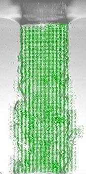

14 Experimental result of atomization behavior 0ms 10ms 20ms 30ms 40ms Diameter=φ10mm 50ms 60ms 70ms 80ms 90ms PIV result of Jet inside flow distribution (3) PVI result Epstein s correlation L D brk = E 0 ρ ρc 1 2 u, ρ dr dt = v en uw, ρ w


15 Velocity distribution and fragmentation behavior Shear stress distribution in x direction
16 Experimental result of et break up length Epstein equation D o L = ( ρ ρ ) 1 2 brk 2E o w E 0 =0.065 Saito equation L D brk J 0 ρ = 2.1 ρw 1 2 V gd 2 J J ( ( ρ ρ c ) Experimental conditions U-alloy78:100~200g 270~300 Water temp.=60-70 Diameter=7-20mm D 0 Fr Epstein type FARO Present experiments CCM PREMIX Saito type Saito MELT2 Moriyama Counter-current flow limitation in debris bed Schematic diagram of test apparatus Bird-eye view of test rig
17 Counter-current flow limitation in debris bed Wallis correlation for gas-liquid flow Void fraction in debris bed Severe Accident s and possible accident management according to the transients management SBO 1-2 hours -Core damage start - Hydrogen generation start Pressure vessel: Loss of cooling capability Possible Management Core cooling at High pressure Without no electricity (Passive cooling system) - IC (gravity driven) / SG - HPCI (steam turbine driven) - RCIC (steam turbine driven) management Depressurization by -SR valve -ADS + Alternative core cooling by Passive cooling system under Low pressure - Pressure increase - Temperature increase Containment vessel: Pressure and temperature increase - Core melt start -> Pressure vessel failure - Large Hydrogen generation Degraded /Melted core behavior - Debris bed cooling - Molten material behavior -IVR Extend containment failure and can wait electricity recover A day - Containment failure Possible Management Steam condensation by - suppression pool scrabbling - PCCS Hydrogen dealing Filtered vent to Prevent CV failure - Depressurization - Heat release
18 Accident progression of light water reactor accident Road map committee on severe accident research in AESJ ( , Organizer: Y. Abe) LOCA RIA phenomena Cooling failure Phase I Severe accident Decay heat removal by Engineering facilities(eccs) Closure of accident Accident management (AM) Phase II Accident progression Containment failure FP release to environment Prevention of nuclear disasters Schematics of Accident management DBA: Succeed decay heat removal by ECCS PCV: High pressure, CV: Low pressure. Fuel is intact. Phase I -AM: Succeed to operate engineering cooling system by alternative emergency power sources to avoid severe accident. Fuel is intact. Phase II-AM: Succeed alternative coolant inection without any electric power source under low PCV pressure. PCV: Low pressure by ADS and/or SRV. CV: Medium pressure below design value. Fuel is intact or slight damaged. No or little FP release to environment. Prevention of nuclear disasters: PCV: High pressure, CV: High pressure Fuel is damaged and is melted. CV is damaged and FP is released to environment. Closure of molten material in damaged PCV and CV.
19 END