Flexural Analysis and Design of Beams. Chapter 3
|
|
|
- Donald Chambers
- 5 years ago
- Views:
Transcription
1 Flexural Analysis and Design of Beams Chapter 3
2 Introduction Fundamental Assumptions Simple case of axial loading Same assumptions and ideal concept apply This chapter includes analysis and design for flexure, dimensioning cross section and reinforcement Shear design, bond anchorage, serviceability in chapters 4, 5, 6.
3 Bending of Homogeneous beam Steel, timber Internal forces-normal and tangential Normal-bending/flexural stress-bending moment Tangential-shear stress-shear force
4 Fundamental assumptions relating to flexure and shear 1. Plane cross section remain plane 2. Bending stress f at any point depends on the strain at that point 3. Shear stress also depends on cross section and stressstrain diagram. Maximum at neutral axis and zero at extreme fibre. Same horizontal and vertical. 4. The intensity of principal stresses
5
6 5. At neutral axis, only horizontal and vertical shear present-pure shear condition 6. When stress are smaller than proportional limit a. Neutral axis = cg b. f=my/i c. v=vq/it d. Shear distribution parabolic, max at na, zero at outer fibre. For rectangular max=1.5v/bh
7 Reinforced Concrete Beam Behaviour
8
9 See video clips Video
10 Stresses elastic, section uncracked Tensile stress in concrete is smaller than modulus of rupture Transformed section can be used
11
12
13 Stresses Elastic, Section cracked Concrete tensile stress exceeds mod of rupture Concrete compressive stress is less than f c /2 Steel stress less than yield Assume tension crack up to neutral axis Transformed section can still be used
14
15
16
17

18
19 Flexural Strength
20 Yielding of steel f s =f y Crushing of concrete ε u = Either Exact shape not necessary Necessary Total compressive force and location βc- location from comp face

21
22 Failure initiated by yielding
23 Failure by concrete crushing Quadratic equation for c
24 Balanced reinforcement ratio ρb
25 Example 3.3
26 Holiday- 1 week Class completed- 10
27 Design of Tension-reinforced Demand < Capacity Rectangular Beams
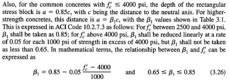
28 Equivalent Rectangular Stress Distribution

29
30
31 Balanced Strain condition
32 Underreinforced beam Compression failure is abrupt Tensile failure gradual ρ should be less than ρ b Read points why?
33 ACI provisions for underreinforced beam ACI establishes some safe limits Net tensile strain Є t at farthest from comp face Strength reduction factor φ
34

35
36
37
38
39
40
41
42
43 Minimum Reinforcement Ratio If the flexural strength (of cracked section) is less than the moment that produced cracking of the previously uncracked section, the beam fails immediately upon formation of first flexural crack. To ensure against this type of failure, a minimum amount of reinforcement is provided
44
45

46
47 Review problem
48
49 Design Problem

50
51
52 Infinite number of solution is possible Economic 0.5ρ to 0.75ρ 0.005
53 Determination of steel area
54
55

56
57

58 Overreinforced beam
59

60 Design Aids: Find Mn
61
62
63 Design Aids: Concrete dimensions and steel
64 Design Aids: find steel area
65 Practical considerations in the design of Beams: Concrete Protection for reinforcement Protection for steel against fire and corrosion Concrete cover depends on member and exposure Surfaces not exposed to ground or weather Not less than ¾ in for slab Not less than 1.5 in for beams and columns Surfaces exposed to weather or in contact with ground At least 2in Cast against ground with no form work Min 3 in cover
66
67 b and h are rounded to 1 or 2 inch Slab rounded to ¼ or ½ inch (greater than 6 inch) Proportions- d 2-3 times of b
68 Selection of bar and spacing No 3 to No 11 for beams No 14 and No 18 for columns Mixing of sizes allowed with 2 bar sizes
69 Gap between bars Clear distance between bars not less than bar dia or 1 inch Two or more layers- min 1 inch Upper bar directly above
70 DOUBLY REINFORCED BEAM Beams with tension and compression reinforcement Cross section is limited Compression steel is used for other reasonslong term deflection, reversal of moment, hanger bar for stirrup
71 Tension and compression steel both at yields
72
73

74 Compression steel below yield stress
75
76
77
78
79
80 Example 3.12
81
82 Nadim Hassoun

83

84
85 Find ϕmn

86

87

88

89

90

91
92 Design of Doubly Reinforced Beam

93

94

95

96

97
98 T-beam
99 RC beam and slab are monolithically cast Beam stirrups and bent bars extend into the slab A part of slab act along with beam top to take longitudinal compression Slab forms the beam flange Part of beam below slab is called web/stem

100 Simplify Effective flange width

101
102 Strength Analysis Two possibilities Just like rectangular beam T-beam analysis required
103 If a>h f T-beam
104
105

106
107
108

109
110
111