The Use of Electro-Coagulation Technology to Treat Hydrofracturing Flowback Water and Other Oil and Gas Field Wastewaters
|
|
|
- Wendy Garrett
- 5 years ago
- Views:
Transcription

1
2 The Use of Electro-Coagulation Technology to Treat Hydrofracturing Flowback Water and Other Oil and Gas Field Wastewaters Randy D. Horsak, PE Principal Engineer Marcellus Shale Water Group, LLC Houston, Texas USA March 22, 2014
3
4 The Shale Oil and Gas Energy Sector in the United States

5
6

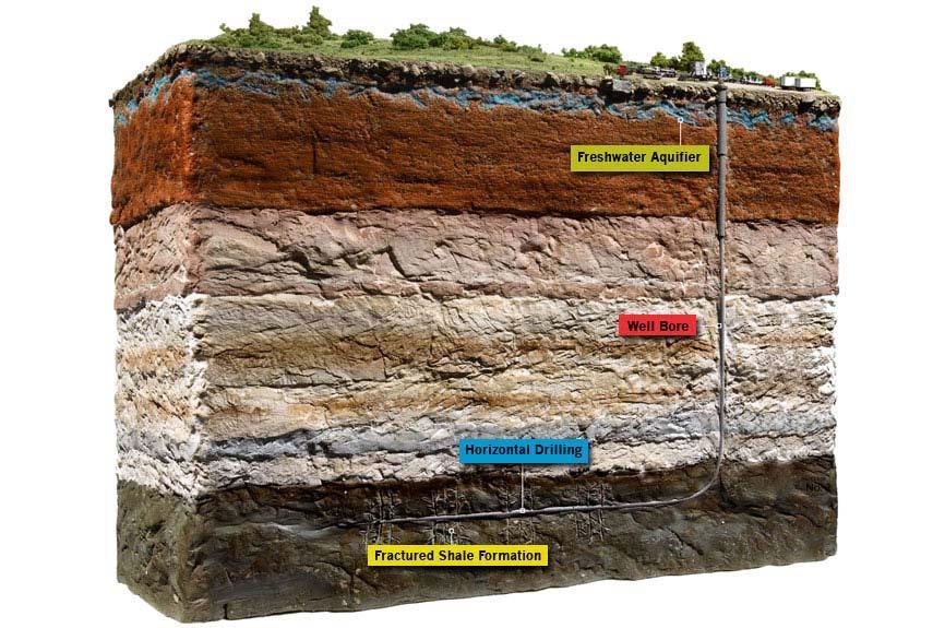
7 What goes down, comes back up DIRTY!

8
9 Water Volumes Required to Drill and Frack Shale Formation Volume of Drilling Volume of Total Volume of Water Per Well Fracturing Water Water Per Well (gallons) Per Well (gallons) (gallons) Barnett Shale 400,000 2,300,000 2,700,000 Fayetteville Shale 60,000 2,900,000 3,060,000 Haynesville Shale 1,000,000 2,700,000 3,700,000 Marcellus Shale 80,000 3,800,000 3,880,000
10 Water Quality in the Marcellus Shale Site Parameters Low Ave High Unit Total Alkalinity mg/l Hardness as CaCO³ 5,100 17,700 55,000 mg/l Total Suspended Solids (TSS) ,220 mg/l Turbidity ,540 NTU Chlorides 26,400 41, ,000 mg/l Total Dissolved Solids (TDS) 38,500 67, ,000 mg/l Specific Conductance 79, , ,000 µmhos/cm Total Kjeldahl Nitrogen mg/l Ammonia Nitrogen mg/l Biochemical Oxygen Demand ,950 mg/l Chemical Oxygen Demand 195 4,870 17,700 mg/l Total Organic Carbon mg/l Dissolved Organic Carbon mg/l Bromide ,190 mg/l

11


12 Composition of Frack Fluid (Frack Fluid may contain up to 600 compounds!)
13 Site Water Balance Fresh Water Recycled Water Influent Equalization Tank or Pond Recovered Oil Tank Effluent Equalization Tank or Pond Discharged Water Reagents Flowback Water Stage I Primary Filtration Stage II Hydrocarbon Removal Hydrocarbon Recovery Stage IV TDS Removal Other Auxiliary Processes Heavy Brine Recovery Oil Product Brine Product Produced Water Stage III Metals / TSS Removal Stage V Disinfection Salt Recovery Waste Residuals
14 Electro-Coagulation System Performance
15 EC Design Configurations

16 Electrode Electrode Floating Floc and Sinking Sludge
17 Electricity EC Module Metrics Chemistry EC Unit Design: Size of EC module Material of electrodes Size of electrodes Configuration of electrodes Spacing of electrodes Voltage and electrical flux Contaminant Removal Rate: ph Concentration Temperature Voltage and electrical flux Treatment residence time Competing chemical reactions Unknown reactants Field Skills Process Flow: Treatment residence time Throughput / flow rate Removal rate of floating floc Removal rate of sinking sludge Feedback loop Treatment end point Contract
18 Untreated Water Source Untreated Water Storage and Equalization Modular, Cascading Treatment Simplified Process Flow Diagram Pump Stage 1 Electro Coagulation Hydrocarbon Recovery Residuals Disposal Stage 2 Reverse Osmosis/ Electro Dialysis Stage 3 Final Polishing HCl and NaOH Recovery Clean Water Storage, Recycle or Discharge
19 Frac Water / Produced Water Stage I Electro-Coagulation Stage II-A Electro-Dialysis Stage II-C Reverse Osmosis HCl NaOH Solid Residue Stage II-B Electro-Dialysis Clean Water HCl NaOH Process Flow Diagram Electro-Coagulation + Reverse Osmosis + Electro-Dialysis

20

21

22 Before EC After EC Clean and Clear Stage II needed?
23 Project Example Woodford Shale, Oklahoma

24

, produce 10-lb saltwater Design Basis: 200-400 gpm / 7,000 14,000 bbl/day (scalable) 24/7 operations TSS reduction >99% Metals reduction >99% Hydrocarbon")
25 Project Overview Oklahoma Woodford Shale Treatment of frac water and produced water Dedicated commercial captive facility Ongoing drilling and fracking operations High variability of influent from multiple wells and locations Current: Discharge to irrigation ponds / receiving stream Future: internal recycle / reuse of effluent Salinity: 10,000 40,000 Cl / 20,000 40,000 TDS Electro-coagulation + carbon filtration + RO + ion exchange Hydrocarbon recovery (<1%) Boron recovery (110 ppm), produce 10-lb saltwater Design Basis: gpm / 7,000 14,000 bbl/day (scalable) 24/7 operations TSS reduction >99% Metals reduction >99% Hydrocarbon reduction >99%

26 Aerial view of the entire site

27 Close-Up Aerial View


28 EC Units Oil Decant Unit Electro-coagulation units and oil decant unit

29 Electro-coagulation units and oil decant unit

30 Power Unit Diesel Unit Power supply system and diesel storage tank

31 Stage I clarifier unit

32 Stage I clarifier unit

33 Stage II activated carbon filtration system (dual units)
34 Stage III ion exchange unit
35 40,000 bbl brine storage unit

36 Stage IV reverse osmosis unit

37 Photograph of Influent and Effluent
38 Project Example Permian Basin, Texas
39 Project Overview Ongoing drilling and fracking operation 3-month project duration Electro-coagulation + some filtration 15,000 20,000 bbl/day 24/7 operations at times TSS reduction >99% Metals reduction >99% Hydrocarbon reduction >99% Salinity reduction not required Recycling of water for fracking

40 Distal view of fracking operation


41 Closer view of drilling and fracking operation

42 Distal view of frac tanks bringing contaminated flowback water to treatment units

43 View of wastewater treatment units

44 Top view of electro-coagulation treatment units


45 Top view of electro-coagulation treatment units

46 Fresh frac water, before and after treatment with only electro-coagulation

47 Day-old frac water, before and after treatment with only electro-coagulation


48 Field Headquarters
49 The Use of Electro-Coagulation Technology to Treat Hydrofracturing Flowback Water and Other Oil and Gas Field Wastewaters Randy D. Horsak, PE Principal Engineer Marcellus Shale Water Group, LLC Houston, Texas USA The wide-scale development of oil shale resources in the United States offers tremendous opportunities in terms of energy production, but unfortunately also presents significant challenges in the use and management of the nation s water resources. The oil and gas energy sector uses huge volumes of water per year. The large and wide-scale requirement for water resources places two primary demands on those resources the need for the large quantity of water, and the associated discharges of contaminated water resulting for the use thereof. Electro-coagulation is a treatment technology that has been successfully used to treat a wide array of wastewaters, but which is just now being introduced to the oil shale resource sector. The technology uses various configurations of electrodes to remove hydrocarbons, total suspended solids, heavy metals, radionuclides, and other contaminants with defined solubility parameters in a cost-effective manner. Contaminants are removed as either a floating floc or a sinking sludge. As a first step in water treatment, electro-coagulation is typically followed by a secondary and even tertiary treatment stage consisting of filtration, reverse osmosis, electro-dialysis, ozonation, and ultra-violet light sterilization. Wastewaters treated with this series of technologies can be recycled / reused, discharged to public waterways, or further treated for potable uses.
50 The Use of Electro-Coagulation Technology to Treat Hydrofracturing Flowback Water and Other Oil and Gas Field Wastewaters Randy D. Horsak, PE Principal Engineer Marcellus Shale Water Group, LLC Houston, Texas USA Randy D. Horsak, PE is a professional engineer in Houston, Texas who has extensive experience in the environmental engineering field, including oil and gas operations. He is the author of more than 50 publications in the field of environmental engineering and science. He is a Principal and Founder of the Marcellus Shale Water Group, a Pennsylvania-based company that provides water and wastewater treatment to the oil and gas sector throughout the United States. Randy D. Horsak, PE Marcellus Shale Water Group, LLC PO Box Houston, Texas USA (281) rhorsak@3tmconsulting.com
51 Contact Information: Randy D. Horsak, PE Marcellus Shale Water Group, LLC PO Box Houston, Texas USA (281)