Co-compression molding of tailored continuous-fiberinserts and inline-compounded long-fiber-thermoplastics
|
|
|
- Joan Marsha Spencer
- 5 years ago
- Views:
Transcription
1 Co-compression molding of tailored continuous-fiberinserts and inline-compounded long-fiber-thermoplastics B.Hangs 1, M. Reif 1, R. Jauch 1, F. Henning 1,2, D. Grauer 3, S. Jespersen 4, A. Martsman 5 SPE ACCE 2012, September 11 13, 2012, Troy (MI, USA) Contact details: Dipl.-Ing. Benjamin Hangs Fraunhofer Institute for Chemical Technology (ICT) Joseph-von-Fraunhofer-Straße Pfinztal benjamin.hangs@ict.fraunhofer.de Phone: +49 (721) Fraunhofer Institute for Chemical Technology (ICT), Pfinztal - Germany 2 Karlsruhe Institute of Technology (KIT) Institute for Vehicle System Technology (FAST), Karlsruhe - Germany 3 Ticona GmbH, Kelsterbach - Germany 4 Fiberforge GmbH, Baar Schweiz 5 Oxeon AB, Borås - Sweden 1


2 - Technologies for hybrid lightweight construction The holistic consideration of materials, production processes and methods in design, simulation and characterization requires new interdisciplinary approaches to realize an intelligent Multi-Material-Design 2
3 Contents Principles of combining continuous-fiber and discontinuous-fiber materials Case-study Underbody shielding Introduction of the study Basic flow-study for improved understanding of mold filling Manufacturing and analysis of a tailored underbody shield demonstrator Conclusion 3
4 Contents Principles of combining continuous-fiber and discontinuous-fiber materials Case-study Underbody shielding Introduction of the study Basic flow-study for improved understanding of mold filling Manufacturing and analysis of a tailored underbody shield demonstrator Conclusion 4
5 Principles of combining continuous-fiber and discontinuous-fiber materials Challenges in applying continuous-fiber semi-finished products Source: Fiberforge Technical challenges Continuous-fiber-reinforced semi-finished products such as wovens or laminates are formed into shell-like structures Limited drapeability and flowability of this material class result in restrictions for freedom of design and part complexity Economical challenges Target costs for monolithic continuous-fiber-reinforced parts are oftentimes hard to achieve in high-volume applications 5
6 Principles of combining continuous-fiber and discontinuous-fiber materials Benefits of continuous-fiber-reinforcements Semi-finished products contain fiber volumes of up to % High mass-specific part properties achievable Part designs can be optimized for specific load cases More stable mechanical performance at elevated temperatures Increased dimensional stability Reduced creep tendency (if loads are transferred into continuous fibers) Application of thermoplastics in strucutral applications Source: Fiberforge 6


7 Principles of combining continuous-fiber and discontinuous-fiber materials Requirements for realizing function-integrated, technical applications Consideration of hybrid structures incorporating continuous- and discontinuous-fiber materials to overcome the technical and economical challenges introduced priorly. 7

8 Principles of combining continuous-fiber and discontinuous-fiber materials Design space and technical requirements Specified installation space and preliminary design based on structural requirements and boundary conditions Structural analysis Determination of main load paths Definition of load bearing and non bearing sections Part optimization Structural and topological optimization algorithms to implement local continuous-fiber-reinforcements Optimized part design Final design including local reinfocements in main load paths 8


9 Principles of combining continuous-fiber and discontinuous-fiber materials Approach for realizing function-integrated parts Combination of local continuous-fiber-reinforcements and established high-volume process technologies Source: Fiberforge 9
10 Contents Principles of combining continuous-fiber and discontinuous-fiber materials Case study Underbody shielding Introduction of the study Basic flow-study for improved understanding of mold filling Manufacturing and analysis of a tailored underbody shield demonstrator Conclusion 10
11 Introduction of the study Requirements for underbody shielding: Protect inner car components against stone impact Reduce air-drag and hence fuel consumption Reduce noise Case study objectives: Achieve an significant increase in impact performance Not within the scope of this presentation Show the feasibility of co-compression-molding UD-tapes and D-LFT to create complex structures Demonstrate high potential of function-integrated components made from discontinuous- and continuous-fiber materials 11
12 Contents Principles of combining continuous-fiber and discontinuous-fiber materials Case study Underbody shielding Introduction of the study Basic flow-study for improved understanding of mold filling Manufacturing and analysis of a tailored underbody shield demonstrator Conclusion 12


13 Basic flow-study for improved understanding of mold filling Materials: D-LFT PP/GF30: Polypropylene reinforced by 30 mass-% discontinuous glass-fibers UD-Tapes PP/GF70: Polypropylene reinforced by 70 mass-% continuous glass-fibers Semi-finished products made from UD-Tape: Tape fabrics Tape laminates Source: Fiberforge 13


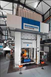
14 Basic flow-study for improved understanding of mold filling Equipment and process parameters: Plaque tool 400 mm x 400 mm, shear edge, no insert fixation, 3 mm plaque thickness Tool temperature: 75 C Hydraulic press Press force and dwell time: kn, 45 s IR oven for heating of continuous-fiber inserts Ceramic IR 350 C Heating time dependent on insert wall thickness 0.5 mm (un-/consolidated) 30 s / 30 s 1.5 mm (un-/consolidated) 140 s / 60 s Source: Dieffenbacher 14

15 Basic flow-study for improved understanding of mold filling Terminology: The following slides do only show a representative excerpt of the performed investigation Dimensions 15


16 Basic flow-study for improved understanding of mold filling Test configurations: 16


17 Basic flow-study for improved understanding of mold filling Summarized results for inserts of 0.5 mm thickness: 1. Tool temperature of 75 C (initial insert temperature: 200 C) causes rapid insert cooling and sticking-effect in the insert/tool interface Even challenging test configurations can be achieved without fixation Tape laminate consolidated Tape laminate consolidated Bottom face Top face Bottom face Top face 17


18 Basic flow-study for improved understanding of mold filling Summarized results for inserts of 0.5 mm thickness: 2. However, if D-LFT causes insert movement, severe insert damage occurs A strong correlation of insert orientation relative to D-LFT flow direction is apparent Tape laminate consolidated Tape laminate consolidated Flow inversion of D-LFT within plaque Bottom face Top face Bottom face Top face 18


19 Basic flow-study for improved understanding of mold filling Summarized results for inserts of 0.5 mm thickness: 3. An initial overlap of the D-LFT strand and tape insert significantly reduces the risk of localized insert damage due to penetration effects. Thin tape fabrics and thin UD laminates are most prone to penetration effects Tape fabric unconsolidated Tape fabric unconsolidated Bottom face Top face Bottom face Top face 19
 Low risk of insert damage Increased risk")
20 Basic flow-study for improved understanding of mold filling Summarized results for inserts of 0.5 mm thickness: Qualitative evaluation of co-molding tape inserts with D-LFT (w/o insert fixation) Low risk of insert damage Increased risk of insert damage High risk of insert damage 20

 and increased amount of inner heat in the insert (slowing")
21 Basic flow-study for improved understanding of mold filling Summarized results for inserts of 1.5 mm thickness: 1. Thicker inserts show increased risk of insert movement and damage, once D-LFT hits the insert during mold filling Main reasons are insert height (obstacle) and increased amount of inner heat in the insert (slowing down insert cooling) Tape laminate consolidated Tape laminate consolidated Bottom face Top face Bottom face Top face 21

22 Basic flow-study for improved understanding of mold filling Summarized results for inserts of 1.5 mm thickness: 2. More pronounced difference between consolidated and unconsolidated material becomes visible Increased risk of D-LFT being pressed in-between plies Tape laminate UNconsolidated Tape laminate consolidated Bottom face Top face Bottom face Top face 22
23 Basic flow-study for improved understanding of mold filling Summarized results for inserts of 1.5 mm thickness: Qualitative evaluation of co-molding tape inserts with D-LFT (w/o insert fixation) Low risk of insert damage Increased risk of insert damage High risk of insert damage 23
24 Contents Principles of combining continuous-fiber and discontinuous-fiber materials Case study Underbody shielding Introduction of the study Basic flow-study for improved understanding of mold filling Manufacturing and analysis of a tailored underbody shield demonstrator Conclusion 24
25 Manufacturing and analysis of a tailored underbody shield demonstrator Part specifications: Material: PP/GF30 Wall thickness: approx. 2.5 mm Mass: approx. 2.8 kg Dimensions: 775 x 1,114 mm² Part made from D-LFT To be modified The mold used is a standard D-LFT production tool and hence not optimized for the specific requirements of co-compression molding with continuous-fiber inserts 25

 Remaining structure as well as complex geometries (e.g. ribs) are made from D-LFT (PP/GF20) 26")
26 Manufacturing and analysis of a tailored underbody shield demonstrator Material components of the demonstrator Areal impact protection made from tape fabric (0.5 mm) Local tailored tape laminates (0.75 mm) Remaining structure as well as complex geometries (e.g. ribs) are made from D-LFT (PP/GF20) 26


27 Manufacturing and analysis of a tailored underbody shield demonstrator D-LFT Tailored tape laminate Tape fabric insert Press cycle of 30 sec (tool temp. 45 C) Modified underbody shield 27
 Positions of samples in the analysis process 28")
28 Manufacturing and analysis of a tailored underbody shield demonstrator Analysis of the underbody shield demonstrator to determine challenges in co-compression molding of tape inserts and D-LFT in complex geometries Preparation of microsections Preparation of SEM pictures CT-scanning (DATA NOT READY YET, WILL BE IMPLEMENTED PRIOR TO SPE ACCE) Positions of samples in the analysis process 28

29 Manufacturing and analysis of a tailored underbody shield demonstrator Degree of deformation of continuous-fiber inserts must be taken into account during part design to avoid imperfectly shaped sections For complex geometries improved tool/handling/preforming technologies become key The standard D-LFT tool used in this study contained a high number of ribbings next to each other Imperfect insert draping vs. This, in combination with the manual handling procedure increased the risk for local imperfections in draping. 29


30 Manufacturing and analysis of a tailored underbody shield demonstrator Highly complex rib structures can be filled by the D-LFT even through continuous-fiber inserts of 1.25 mm thickness Current investigations focus on the quantitative determination of filter effects caused by the continuous-fiber inserts Matrix washout from UD-tape materials 30


31 Manufacturing and analysis of a tailored underbody shield demonstrator Penetration of thin tape fabrics (here: 0.5 mm) is concentrated in areas of tape strip crossings Fibers in thin tape laminates (not shown here) with pure UD orientation tend to be pushed apart by the D-LFT perpendicular to the 0 direction of fibers 0 D-LFT flow path 31


32 Manufacturing and analysis of a tailored underbody shield demonstrator Co-compression molding of D-LFT and continuous-fiber inserts can result in severe local insert damage The presented demonstrator was a feasibility study based on a standard D-LFT mold. No measures could be taken for process optimization. Adjustments such as automated handling, insert fixation, tool heating etc. could improve results significantly. 32


33 Manufacturing and analysis of a tailored underbody shield demonstrator Despite the discussed challenges, the feasibility study did show that in most areas of the demonstrator, severe insert damage was avoided even without complex processing technologies 33
34 Contents Principles of combining continuous-fiber and discontinuous-fiber materials Case study Underbody shielding Introduction of the study Basic flow-study for improved understanding of mold filling Manufacturing and analysis of a tailored underbody shield demonstrator Conclusion 34
 serial production part was modified by implementing inserts made from UD-tapes.")
35 Conclusion A basic flow-study was conducted to create an improved understanding of the limits in co-compression molding of D-LFT and continuous-fiber inserts It was shown that even without insert fixation even complex combinations are feasible A complex high-volume (former) serial production part was modified by implementing inserts made from UD-tapes. Even with numerous limitations (low tool temp., manual insert and D-LFT handling, no insert fixation etc.) the feasibility of manufacturing highly-complex parts using co-compression molding of D-LFT and continuous-fiber inserts was shown 35
36 Acknowledgment Many thanks for a very good collaboration in this project to Furthermore the project partners thank for providing the serial production tool used in the underbody manufacturing For the financial support related to establishing the Fraunhofer Project Group Functional Lightweight Design gratitude goes to the Free State of Bavaria and the city of Augsburg. 36
37 Contact details Daniel Grauer ; Tel.: Andreas Martsman ; Tel.: Simon Jespersen ; Tel.: