Use of Long Fiber Thermoplastic in Automotive Market Creig Bowland President Colorado Legacy Group LLC
|
|
|
- Kerrie Lamb
- 5 years ago
- Views:
Transcription

1 Use of Long Fiber Thermoplastic in Automotive Market Creig Bowland President Colorado Legacy Group LLC Vanja Ugresic Research Engineer Fraunhofer Project Western University

2 Projected Material use in Automotive Industry
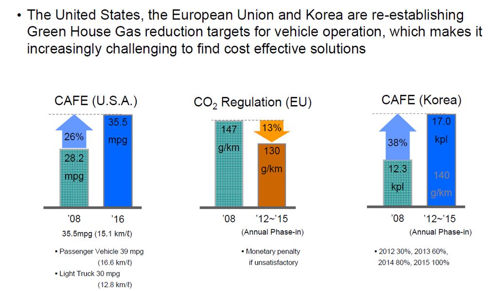
3 Regulations-Driving Change

4 Motivation for Lightweight Design Weight increase of typical medium-class vehicle since 1970 Implementation of CAFE regulation Goals: Reduction of consumption and emissions through lighter structures Improvement of passive and active safety and product attractiveness through functional design Reliable and consistent technologies capable of economically viable, small and large production volumes
5 The LFT Market Long Fiber Thermoplastics annual growth 13% to 17% over 15 years. Growth projected at 13% per year through Offering solutions for metallic and structural applications. Credible engineering, design and processing database.

6 Global LFT Demand History & Forecast

7 Processing Technologies Classification according to matrix type and fiber length

8 Processing Technologies Classification according to production volumes Quelle: in Anlehnung an Prof. Schemme
9 Processing Technologies Classification according to fiber length: 1. Short fiber processes: o Based on injection moulding and injection-compression Thermoplastics Themosets 2. Long fiber processes: o Based on compression moulding Thermoplastics Themosets 3. Continuous fiber processes: Thermoplastics Thermosets

10 Fiber Reinforced Thermoplastics Short Long Continuous

11 Fiber Reinforced Thermoplastics Property comparison of short and long 40wt% PP

12 Fiber Reinforced Thermoplastics Impact property comparison of short and long of 30wt% and 50wt% nylon
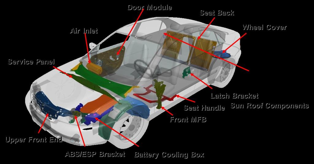

13 Automotive LFT Application

14 Long Fiber Thermoplastics Technologies
15 Long Fiber Thermoplastics Technologies Compression: High volume production Very large, shell like parts Most important processing technologies include LFT-G, LFT-D-ECM, GMT, GMTex, LWRT Injection molding: High-volume production Compact parts with complex geometry LFT-G, LFT-D-ILC
16 Basics of processing Mechanical properties of parts made from FRP are strongly dependent on processing parameters and material components Examples of processing parameters: Tool temperature, injection speed and pressure etc. Influence: Orientations of molecular chains and fibers Internal stresses and warpage Crystallinity Molecular structure (molar mass and ist distribution) Fiber content, additives, fillers
17 Basics of processing Basics for processing fiber reinforced thermoplastics Processing temperature Thermoplastics approx C High performance polymers require even higher temperatures (e.g. PPS at approx. 340 C) Tool temperature Thermoplastics: Tool is cooled approx C Heat needs to be removed from the plastic. By cooling the plastic, the tool heats up
18 Basics of processing Pressures needed to process: Thermoplastics approx bar Compression molding: bar Injection molding: bar Achievable cycle times vary for the different material classes Thermoplastics Mostly dependent on wall thickness and cooling rate (tool temperature) Usually approx. 20 s up to several minutes
19 Basics of processing Orientations of molecular chains and fibers in a part are mostly determined by: Part geometry Type of gate and its position (injection molding) Injection speed (injection molding) Tool closing speed (compression molding) Tool temperature cycle time Viscosity Fiber content
20 Basics of processing Internal stresses and warpage Stresses (due to processing) within a part are mostly determined by: Part geometry (e.g. Symmetric shape) Degree of orientation for molecules and fibers Wall thickness distribution Tool temperature cycle time Shrinkage Fiber content

21 Basics of processing Internal stresses and warpage Internal stresses due to tool temperature Temperature distribution Warm core, cold next to tool surface Wall thickness After cooling: if all layers could contract indipendently» No internal stresses» After cooling: with real limitations regarding material contraction Internal stresses Thermal contraction Skript: Konstruieren mit Kunststoffen, Bonten

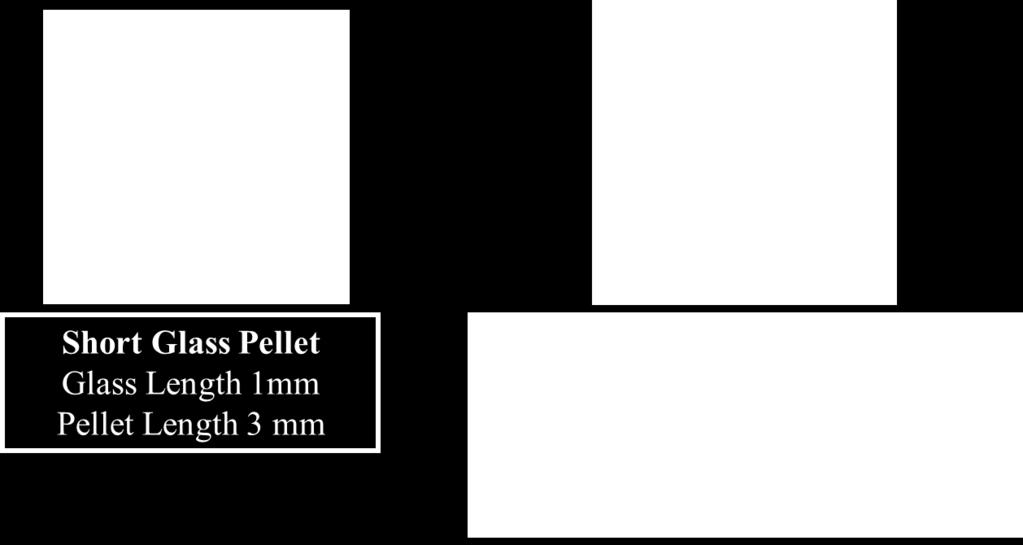
22 Long Fiber Thermoplastics Granules LFT-G
23 LFT-G Pellet Manufacturing Pellet pultrusion processing
24 LFT Injection Moulding Processing LFT can easily and repeatedly be molded into quality structural parts Requires minimal modification to most standard equipment Requires a low shear screw A free flow or ring check valve Sprew Diameter minimum of ¼ Runner Diameter minimum of ¼ Slightly higher processing temperatures Large Gates Good Venting in the Mold Low backpressure Low to Medium Injection Pressure


25 LFT Injection Moulding Processing 30wt% Long glass polypropylene moulding profile

26 LFT Injection Moulding Processing Suggested check valve design

27 LFT-G Injection Example Replacing Stamped Steel Part 30-40% PP LFT Done by LFT-G IM or LFT-D- ILC Weight and Cost Reduction Part Integration and Design Flexibility Door Carrier Plate
 Wet/dry interface to engine compartment Cost/weight reduction Multiple part integration Design freedom for further part")
28 LFT-G Injection Example Automotive Instrumental Panel 40% glass filled LFT PP Large part metal replacement Acoustic part (Noise reduction) Wet/dry interface to engine compartment Cost/weight reduction Multiple part integration Design freedom for further part consolidation


29 LFT-G Injection Example Older Application of PP LFT-G Battery Tray and Enclosures since: Acid Resistant Heat Resistant Newer Application of PP LFT-G Air Bag Retainer Box Replacing Zinc Die Cast Parts

30 Case Study LFT-D CM Underbody Shield Stiffness Impact Corrosion & impact protection Cw & fuel economy Large series Low cost & weight
31 Drivers for LFT Parts Example: Golf A2 and A3 Front End Assembly Weight Reduction Part reduction Reduced assembly procedures


32 LFT-Direct Technologies LFT-Direct: - Motivation for a direct LFT process is the more direct process chain - LFT-D-ECM compression moulding - LFT-D-ILM injection moulding Standard process LFT-D Process Quelle: Rieter Automotive/ Fh ICT
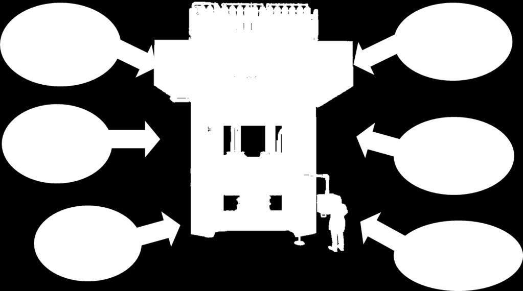
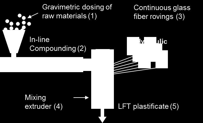
33 LFT-D-ECM Gravimetric dosing of raw materials (1) Continuous glass fiber rovings (3) Hydraulic Press Gravimetric dosing of raw materials (1) In-line Compounding (2) Continuous glass fiber rovings (3) Hydraulic Press Compounding and mixing extruder(2) One machine technology Lower investment Limited versatility Shorter fiber length Lower material throughput LFT-plastificate (4) Mixing extruder (4) LFT plastificate (5) Two machine technology Lower fiber damage due to optimized system In-line compounding reduces cost and increases versatility High material throughput with long resulting fibers

34 LFT-D-ECM Process Schematic Automation of the entire production line Conveyer belt for LFT plastificate Hydraulic Press Compression moulding Dosing unit Glass fiber rovings In-line Compounding LFT extrusion die Mixing extruder Quelle: Rieter Automotive/ Fh ICT
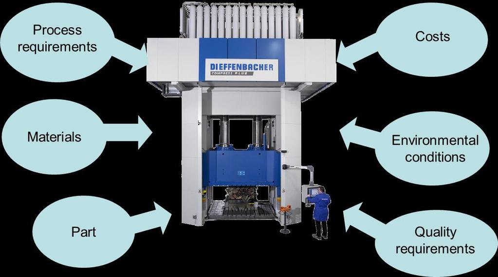

35 LFT-D-ECM Requirements for compression molding process technologies Quelle: Dieffenbacher


36 Mold Filling Process Requirements LFT-D-ECM General mold filling process for LFT Mold coverage 30-50% Material flow distance about 30 to 40 cm Long flow requires higher press capacity, pressure required bar Filling of ribs and complex geometry are feasible Cycle times seconds


37 Mold Filling Process Requirements LFT-D-ECM Understanding the flow behaviour, fiber orientation and required pressing forces Approximation of these parameters can be done through mold filing studies which require following steps: Closing the mold using a blocking - LFT will be cooled and flow behavoiur studied Variying the mold blocks to achieve mold filling pattern (next slide) Analysing the flow distance and prediction of weld lines Analysing the press force vs the mold gap allows calculation of total press force required
38 Mold Filling Process Requirements LFT-D-ECM Varying the mold blocks to achieve mold filling pattern F F F


39 Mold Filling-Charge Placement Process Requirements LFT-D-ECM Symmetrical and asymmetrical plastificate placement Parallel levelling system required Moment (created by plastificate) Moment (created by parallel leveling system) Symmetric plastificate placement Asymmetric plastificate placement

40 Mold Filling- Multiple Charges Process Requirements LFT-D-ECM Placement of multiple LFT plastificates For complex geometries, one piece of LFT plastificate is probably not suffiecient to fill the mold properly Solution: Placement of multiple pieces Avoids asymmetric moments Issue: Weld lines due to multiple LFT plastificates
41 Mold Filling- Multiple Charges Process Requirements LFT-D-ECM Profiled plastificates to avoid weld lines Results in less material flow i.e. Reduced press force Reduced fiber orientations in the part (less anisotropic) F F F

42 400 mm LFT Parts Fiber orientation after the form filling process Initial position of LFT plastificate Positions of test specimens 0 90


43 LFT-D Application Spare Wheel Cover-VW Touran Material: LFT-D 20 PP Weight: 2,3 kg Dimensions: 730 x 690 x 18 mm Visible grained surface Cycle time: 25 sec Hydraulic fast-closing press Extruder capacity: 480 kg/h

44 Multi-Material Concept Intelligent combination of different materials (MMD): Join the best Material substitution no longer effective-holistic approach required Suitable joining technologies or intelligent intrinsic hybridization required


45 Composite technologies and hybridization Utilization of established composite technologies with mass production potential Local hybridization, and functionalization of composites with reinforcements made of steel, UD or textile fiber reinforcements, foams

46 Interdisciplinary, holistic approach Holistic consideration of materials, production processes and methods leads to new construction methods in multimaterial design
47 Continuous Fiber-Reinforced Thermoplastic (T-LFT) Advantages of local continuous fiber reinforcements High potential for lightweight desgin due to specific material properties Low creep tendency Optimized part reinforcement Optimized, load dependent fiber orientations Prepreg material lower risk of voids in the final part High fiber volume fraction of %
 Load transfer into local continuous")


48 Continuous fiber-reinforced Thermoplastic (T-LFT) Load transfer into local continuous fiber-reinforcements Development of novel solutions for load transfer into molded, continuous-fiber-reinforced structures is important Maximizing effects of fiber-reinforcement Creating guidelines for proper part design Types of reinforcement: Tapes Organo sheets Fabric Filament wound structures Metallic inserts (e.g. wound loops) Composite inserts (e.g. thermoformed)

49 Continuous fiber-reinforced Thermoplastic Tailored LFT (T-LFT)
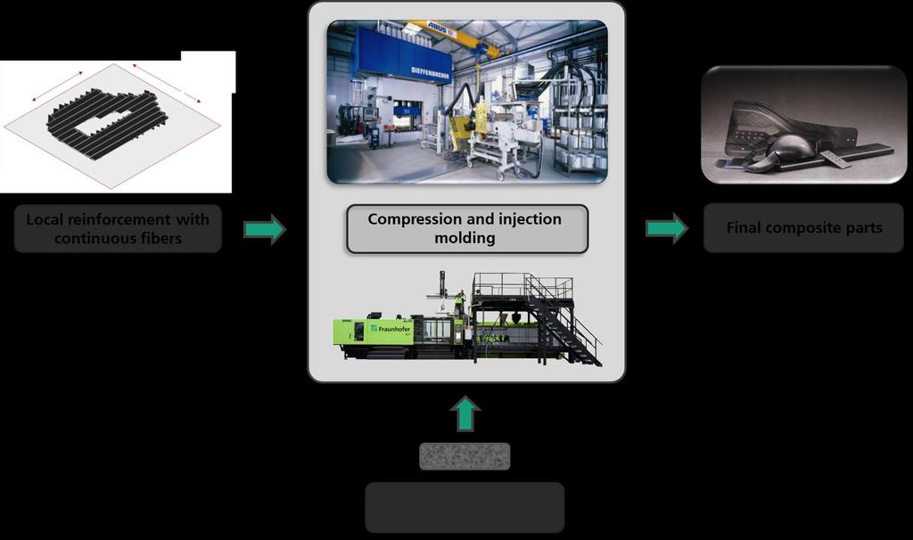
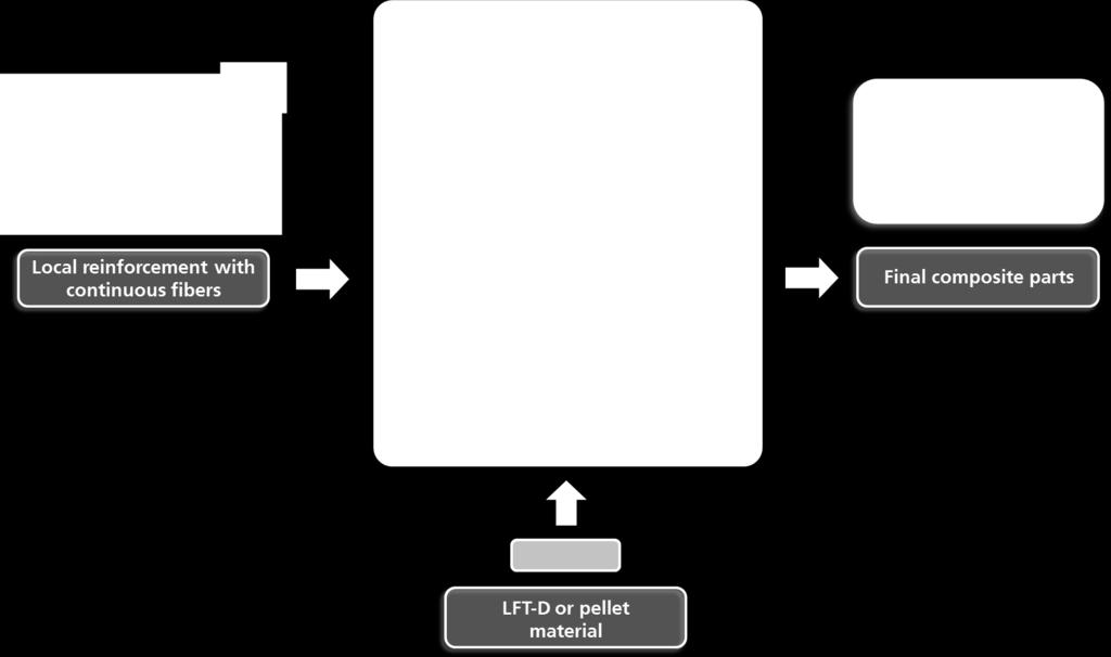
50 Continuous fiber-reinforced Thermoplastic (T-LFT)


51 Continuous Fiber Reinforced - Thermoplastic (T-LFT) Types of local continuous reinforcements: Textile reinforcement Metallic inserts Continuous fibers Textile reinforcement Unidirectional fibers Metal components Metallic inserts


52 Continuous fiber-reinforced Thermoplastic (T-LFT) Wound and UD reinforcements Manufacturing of preimpregnated fibers Handling and transfer of reinforcing structure Processing to final part

53 Continuous Fiber Reinforcement Thermoplastic Back molding of textiles and decor foil Back molded material provided structural stability E.g. textile material 1. Fix textile in tool and close tool 2. Inject material 3. Dwell time 4. Demolding Skript: Konstruieren mit Kunststoffen, Bonten Quelle: Fraunhofer ICT
54 Continuous fiber-reinforced Thermoplastics Thermoplastic tape-placement Processing of unidirectional prepreg tapes Manufacturing of shell-like parts for structural applications Most common machine types: Gantry systems (Especially for very large structures) Robot-based processes with tape-placement according to final geometry Tape-placement on flat surface with subsequent forming Material throughput: Most processes deliver approx kg/h Hence especially interesting for lower volumes For thermoset systems, curing time has to be taken into account
55 Bildquelle: Fiberforge Bildquelle: Fiberforge Continuous fiber-reinforced Tape placement Bildquelle: Coriolis Composites Bildquelle: Fiberforge Bildquelle: M Torres
56 Bildquelle: Fiberforge Continuous fiber-reinforced Tape placement Advantages of unidirectional tape structures High fiber content of Vol-% Nearly no limitation regarding polymer selection Completely impregnated fibers lower risk of dry fiber spots Several suppliers No handling of chemicals (thermoplastic materials) Clean processing (especially thermoplastic materials)
57 Continuous Fiber-Reinforced FPR- Tape placement Advantages of thermoplastic Tapes: Faster cycle times through faster curing of the matrix (cooling at Tg) High Impact strength high compared to thermosets Very clean environment and process control Thermoplastic joining processes applicable (esp. Welding processes) Unlimited storage Subsequent curing is omitted, eg. No autoclaves Advantages of thermoset Prepreg: Less problems regarding to heat distortion/resistance and partly on chemical resistance Already established in aviation industry


58 Continuous fiber-reinforced FRP Tapes Advantages of tape placement Fiber orientations within the laminate is arbitrarily adjustable Varying wall thickness Minimized scrap Hybrid laminates Variation of fiber or matrix type, fiber volume fraction etc. Automized process with and high reproducibility and accuracy
59 Bildquelle: Fiberforge Continuous fiber-reinforced FRP Tape placement Benefits of thermoplastic UD-tapes Short cycle times High toughness compared to thermosets Very clean processing Recyclable Thermoplastic joining technologies applicable (especially welding) No limited storage time

60 Continuous fiber-reinforced FRP Thermoplastic Tape placement Manufacturing of tape layups using Fiberforge s RELAY process Tape placement on flat surface Plies are locally connected by ultrasonic welding This stage is called unconsolidated tape layup Unidirectional Tape RELAY Station Tailored Blank Ultrasonic welding Bildquelle: Fiberforge


61 Continuous fiber-reinforced FRP Thermoplastic Tape Placement Part manufacturing using unconsolidated tape layups Stamp forming
62 Thank You