Chapter 3 Prescriptive Process Models
|
|
|
- Garey Lucas
- 5 years ago
- Views:
Transcription
1 Chapter 3 Prescriptive Process Models - Generic process framework (revisited) - Traditional process models - Specialized process models - The unified process
2 Generic Process Framework Communication Involves communication among the customer and other stake holders; encompasses requirements gathering Planning Establishes a plan for software engineering work; addresses technical tasks, resources, work products, and work schedule Modeling (Analyse, Design) Encompasses the creation of models to better understand the requirements and the design Construction (Code, Test) Combines code generation and testing to uncover errors Deployment Involves delivery of software to the customer for evaluation and feedback 2
3 Modeling: Software Requirements Analysis Helps software engineers to better understand the problem they will work to solve Encompasses the set of tasks that lead to an understanding of what the business impact of the software will be, what the customer wants, and how end-users will interact with the software Uses a combination of text and diagrams to depict requirements for data, function, and behaviour Provides a relatively easy way to understand and review requirements for correctness, completeness and consistency 3
4 Modelling: Software Design Brings together customer requirements, business needs, and technical considerations to form the blueprint for a product Creates a model that provides detail about software data structures, software architecture, interfaces, and components that are necessary to implement the system 4
5 Software Design Architectural design Represents the structure of data and program components that are required to build the software Considers the architectural style, the structure and properties of components that constitute the system, and interrelationships that occur among all architectural components User Interface Design - GUI Creates an effective communication medium between a human and a computer Identifies interface objects and actions and then creates a screen layout that forms the basis for a user interface prototype Component-level Design Defines the data structures, algorithms, interface characteristics, and communication mechanisms allocated to each software component
6 Traditional Process Models
7 Prescriptive Process Model Defines a distinct set of activities, actions, tasks, milestones, and work products that are required to engineer high-quality software The activities or the process flow may be linear, incremental, or evolutionary Basically it populates a process framework with explicit task sets for software engg actions Prescribes a set of process elements- framework activities, SE actions, tasks, work products, QA and change control mechanisms for each project. 7
8 Waterfall Model (Diagram) Communication Project initiation Requirements gathering Planning Estimating Scheduling Tracking Modeling Analysis Design Construction Code Test Deployment Delivery Support Feedback 8
9 Waterfall Model (Description) Oldest software lifecycle model and best understood by upper management Used when requirements are well understood and risk is low Work flow is in a linear (i.e., sequential) fashion Used often with well-defined adaptations or enhancements to current software and when project is small 9
10 Waterfall Model (Problems) Doesn't support iteration, so changes can cause confusion Difficult for customers to state all requirements explicitly and up front Requires customer patience because a working version of the program doesn't occur until the final phase Problems can be somewhat alleviated (eased) in the model through the addition of feedback loops Video Tour 10
11 Real life examples for water fall model Like automobile companies make cars and bikes. when they are building a car, the requirements are fixed, predefined. There will be no change in the requirements during the process of building a car. Once we complete a stage, we proceed to the next one. if there is any change in requirements come then we have to go back and make those changes. Then we have to change our complete system that requires extra time and extra money. This is a major disadvantage of water fall model.
12 Software Functionality and Features Incremental Process Models (1) Communication Planning Modeling (analysis, design) increment # n Construction (code, test) Deployment (delivery, feedback) increment # 2 delivery of nth increment increment # 1 delivery of 1 st increment Project Calendar Time The incremental model delivery of 2 nd increment 13
13 Incremental Process Models (2) Combines elements of the waterfall model applied in an iterative fashion The whole requirement is divided into various builds. Multiple development cycles take place here, making the life cycle a multi-waterfall cycle. Each linear sequence produces deliverable increments of the software The first increment is often a core product The core product is used by the customer (or undergoes detailed evaluation) Based on evaluation results, a plan is developed for the next increment 14
14 Incremental Process Models (3) The incremental process model, like prototyping and other evolutionary approaches, is iterative in nature Particularly useful when Staffing is unavailable (Early increments can be implemented with fewer people) Increments can be planned to manage technical risks (eg: dependency of system on new under development hardware) 15
15 Incremental Model Used when requirements are well understood Needs a clear and complete definition of the whole system before it can be broken down and built incrementally. Multiple independent deliveries are identified Work flow is in a linear (i.e., sequential) fashion within an increment. Iterative in nature; focuses on an operational product with each increment Provides a needed set of functionality sooner while delivering optional components later Useful also when staffing is too short for a full-scale 16 development.
16 Incremental Model (When to Use?) Requirements of the complete system are clearly defined and understood. A new technology is being used Resources with needed skill set are not available There is a need to get a product to the market early.
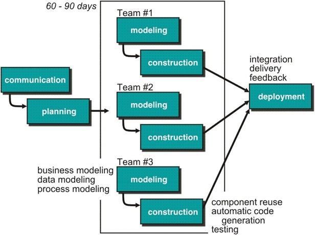
17 RAD Model
18 RAD Model(1) RAD model is Rapid Application Development model. In RAD model the components or functions are developed in parallel as if they were mini projects. The developments are time boxed, delivered and then assembled into a working prototype. This can quickly give the customer something to see and use and to provide feedback regarding the delivery and their requirements.
19 RAD Model (Advantages) Reduced development time. Increases reusability of components Quick initial reviews occur Encourages customer feedback
20 RAD Model (Disadvantages) For large projects, RAD requires sufficient human resources to create right number of RAD teams If developers and customers are not committed to the rapid fire activities the project may fail Only system that can be modularized can be built using RAD RAD may not be appropriate when technical risks are involved
21 RAD Model (When to Use?) RAD should be used when there is a need to create a system that can be modularized in 2-3 months of time. It should be used if there s high availability of designers for modeling and the budget is high enough to afford their cost along with the cost of automated code generating tools. RAD should be chosen only if resources with high business knowledge are available and there is a need to produce the system in a short span of time (2-3 months).
22 Prototyping Model (Diagram) Quick Planning Start Communication Deployment, Delivery, and Feedback Modeling Quick Design Construction Of Prototype 23
23 Prototyping Model (Description) Follows an evolutionary and iterative approach Used when requirements are not well understood Instead of freezing the requirements before a design or coding can proceed, a throwaway prototype is built to understand the requirements. By using this prototype, the client can get an actual feel of the system, since the interactions with prototype can enable the client to better understand the requirements of the desired system. Feedback is used to refine the prototype Prototyping is an attractive idea for complicated and large 24
24 Prototyping Model (Potential Problems) The customer sees a "working version" of the software, wants to stop all development and then buy the prototype after a "few fixes" are made Developers often make implementation compromises to get the software running quickly (e.g., language choice, user interface, operating system choice, inefficient algorithms) 25
25 Prototyping Model (When to Use?) Prototype model should be used when the desired system needs to have a lot of interaction with the end users. Typically, online systems, web interfaces have a very high amount of interaction with end users, are best suited for Prototype model. Prototyping ensures that the end users constantly work with the system and provide a feedback which is incorporated in the prototype to result in a useable system. They are excellent for designing good human computer interface systems.
26 Spiral Model (Diagram) Planning Communication Start Modeling Start Deployment Construction 27
27 Spiral Model (Description) Invented by Dr. Barry Boehm in Follows an evolutionary approach Used when requirements are not well understood and risks are high. Inner spirals focus on identifying software requirements and project risks; may also incorporate prototyping Outer spirals take on a classical waterfall approach after requirements have been defined, but permit iterative growth of the software Operates as a risk-driven model a go/no-go decision occurs after each complete spiral in order to react to risk determinations Requires considerable expertise in risk assessment Serves as a realistic model for large-scale software development 28
28 Spiral Model (Advantages) High amount of risk analysis hence, avoidance of Risk is enhanced. Good for large and mission-critical projects. Additional Functionality can be added at a later date. Software is produced early in the software life cycle.
29 Spiral Model (Disadvantages) Can be a costly model to use. Budget is not fixed. Risk analysis requires highly specific expertise. Project s success is highly dependent on the risk analysis phase. Doesn t work well for smaller projects.
30 Spiral Model (When to Use?) When costs and risk evaluation is important For medium to high-risk projects Users are unsure of their needs Requirements are complex Significant changes are expected (research and exploration) Eg: Microsoft Operating System
31 General Weaknesses of Evolutionary Process Models 1) Prototyping poses a problem to project planning because of the uncertain number of iterations required to construct the product 2) Evolutionary software processes do not establish the maximum speed of the evolution If too fast, the process will fall into chaos If too slow, productivity could be affected 3) Software processes should focus first on flexibility and extensibility, and second on high quality We should prioritize the speed of the development over zero defects Extending the development in order to reach higher 32 quality could result in late delivery
32 Specialized Process Models
33 Component-based Development Model Consists of the following process steps Available component-based products are researched and evaluated for the application domain in question Component integration issues are considered A software architecture is designed to accommodate the components Components are integrated into the architecture Comprehensive testing is conducted to ensure proper functionality Relies on a robust component library Capitalizes on software reuse, which leads to documented savings in project cost and time 34
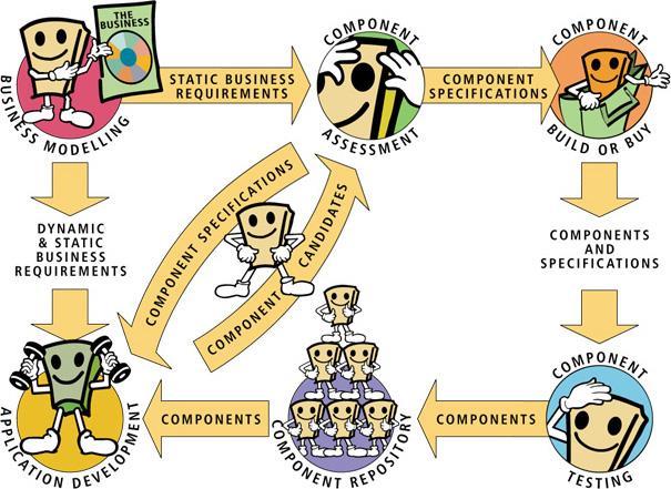
34
35 Formal Methods Model (Description) Encompasses a set of activities that leads to formal mathematical specification of computer software Enables a software engineer to specify, develop, and verify a computer-based system by applying a rigorous, mathematical notation Ambiguity, incompleteness, and inconsistency can be discovered and corrected more easily through mathematical analysis Offers the promise of defect-free software Used often when building safety-critical systems Eg: Train Stop System, Medical devices 36
36 Formal Methods Model (Challenges) Development of formal methods is currently quite time-consuming and expensive Because only few software developers have the necessary background to apply formal methods, extensive training is required It is difficult to use the models as a communication mechanism for technically unsophisticated customers 37
37 Aspect-Oriented Software Development As modern computer-based systems become more sophisticated (and complex), certain concerns customer required properties or area of technical interest span the entire architecture.(security in modern Banking Software) When concerns cut across multiple system functions, features, and information, they are often referred to as crosscutting concerns(aspects). Aspect-oriented software development (AOSD), often referred to as aspect-oriented programming (AOP), is a relatively new software engineering paradigm that provides a process and methodological approach for defining, specifying, designing, and constructing aspects
38 The Unified Process
39 Background Born during the late 1980's and early 1990s when object-oriented languages were gaining wide-spread use Many object-oriented analysis and design methods were proposed; three top authors were Grady Booch, Ivar Jacobson, and James Rumbaugh They eventually worked together on a unified method, called the Unified Modeling Language (UML) UML is a robust notation for the modeling and development of object-oriented systems UML became an industry standard in 1997 However, UML does not provide the process framework, only the necessary technology for object-oriented development 40
40 Background (continued) Booch, Jacobson, and Rumbaugh later developed the unified process, which is a framework for object-oriented software engineering using UML Draws on the best features and characteristics of conventional software process models Emphasizes the important role of software architecture Consists of a process flow that is iterative and incremental, thereby providing an evolutionary feel Consists of five phases: inception, elaboration, construction, transition, and production 41
41 ATM Simulation Example A controller object representing the ATM itself (managing the boundary objects listed below.) Boundary objects representing the individual component parts of the ATM: Operator panel. Card reader. Customer console, consisting of a display and keyboard. Network connection to the bank. Cash dispenser. Receipt printer.

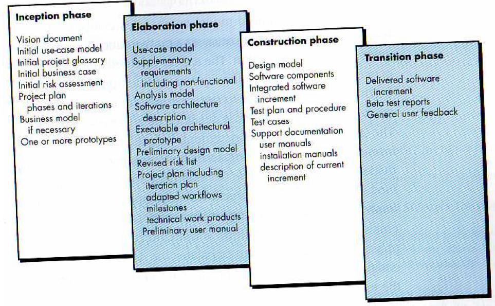
42 Phases of Unified Process
43 Inception Phase Encompasses both customer communication and planning activities of the generic process Business requirements for the software are identified A rough architecture for the system is proposed A plan is created for an incremental, iterative development Fundamental business requirements are described through preliminary use cases A use case describes a sequence of actions that are performed by a user 44
44 Elaboration Phase Encompasses both the planning and modeling activities of the generic process Refines and expands the preliminary use cases Expands the architectural representation to include five views Use-case model Analysis model Design model Implementation model Deployment model Often results in an executable architectural baseline that represents a first cut executable system The baseline demonstrates the viability of the architecture but does not provide all features and functions required to use the system 45
45 Construction Phase Encompasses the construction activity of the generic process Uses the architectural model from the elaboration phase as input Develops or acquires the software components that make each use-case operational Analysis and design models from the previous phase are completed to reflect the final version of the increment Use cases are used to derive a set of acceptance tests that are executed prior to the next phase 46
46 Transition Phase Encompasses the last part of the construction activity and the first part of the deployment activity of the generic process Software is given to end users for beta testing(user acceptance testing) and user feedback reports on defects and necessary changes The software teams create necessary support documentation (user manuals, trouble-shooting guides, installation procedures) At the conclusion of this phase, the software increment becomes a usable software release 47
47 Production Phase Encompasses the last part of the deployment activity of the generic process On-going use of the software is monitored Support for the operating environment (infrastructure) is provided Defect reports and requests for changes are submitted and evaluated 48
48 Unified Process Work Products Work products are produced in each of the first four phases of the unified process In this course, we will concentrate on the analysis model and the design model work products Analysis model includes Scenario-based model, class-based model, and behavioral model Design model includes Component-level design, interface design, architectural design, and data/class design 49
49
50 Six Best Practices RUP (IBM) These best practices are followed to minimize faults and increase productivity. 1. Develop iteratively-it is best to know all requirements in advance; however, often this is not the case. Several software development processes exist that deal with providing solution on how to minimize cost in terms of development phases.
51 Six Best Practices RUP (IBM) 2. Manage requirements - Always keep in mind the requirements set by users. 3. Use components - Breaking down an advanced project is not only suggested but in fact unavoidable. This promotes ability to test individual components before they are integrated into a larger system. Also, code reuse is a big plus and can be accomplished more easily through the use of object-oriented programming.
52 Six Best Practices RUP (IBM) 4. Model visually - Use diagrams to represent all major components, users, and their interaction. "UML", short for Unified Modeling Language, is one tool that can be used to make this task more feasible. 5. Verify quality - Always make testing a major part of the project at any point of time. Testing becomes heavier as the project progresses but should be a constant factor in any software product creation.
53 Six Best Practices RUP (IBM) 6. Control changes - Many projects are created by many teams, sometimes in various locations, different platforms may be used, etc. As a result it is essential to make sure that changes made to a system are synchronized and verified constantly.