Extrusion Blow Molded 4ft Step Ladder. Kevin Orndorf Nigel Robertshaw Penn State Erie The Behrend College
|
|
|
- Felix Burns
- 5 years ago
- Views:
Transcription
1 Extrusion Blow Molded 4ft Step Ladder Kevin Orndorf Nigel Robertshaw Penn State Erie The Behrend College April 14, 2017
2
3 Extrusion Blow Molded 4ft Step Ladder Abstract The proposed product is an innovative new 4ft Ladder blow molded as a single piece with a hinge made of TPV using an intermittent parison extrusion with two extrusion heads. The product will be made of glass filled PP with the hinge formed, as stated above, from TPV. The ladder is intended for use by homeowners and for light construction work and will have a 200 lb OSHA load rating. There are no blow molded ladders currently available on the market. This product eliminates the labor-intensive assembly of the currently produced aluminum, wood and fiberglass ladders and thus will be less costly to produce. It also has greater design freedom in terms of styling because of the manufacturing method used and thus can be more aesthetically pleasing than what is currently available on the market. Because it is made of lightweight PP, the ladder will be lightweight, which will make it more ergonomic for consumers to use. In summary, the ladder proposed will be both easier to produce and offer higher functionality than the current ladders made without the benefit of blow molding technology. Introduction There are few tools with the utility and downright value to human civilization as ladders. Ladders have been utilized by humans to build cities, ships, explore the Kevin Orndorf, Nigel Robertshaw Penn State Erie, the Behrend College unexplored, and much more for millennia. The basic concept of the ladder has not changed much in this time with the largest changes just being in the material they are created with. One of the largest and most substantial innovations in ladder technology came in 1862 at the hands of a Pennsylvanian inventor John Basely. Basely created the first collapsible step ladder that could be stored away when not in use. The main intent for step ladders is their convenience and size in this case a 4ft step ladder. The former large single sided ladders are not of convenience or use in and around the house because it is necessary to have a wall to lean the ladder against. The step ladder allows for effective use of ladders just about anywhere. Target Market The target market for the 4ft blow molded step ladder would be homeowners and do it yourselfers needing a light duty ladder at a reasonable price point. The ladder would be intended for around the house use and outdoor use on relatively flat surfaces like driveways, patios, and even gardens. The elastomer feet would prevent scratching wood floors, nicking of tile and prevent slipping on these surfaces also. The ladder is designed small enough in size it could be stored away easily in a closet. It could be stored in a damp garage or shed or outside under a tarp due to moisture not affecting the material like with wood or aluminum ladders.
4 Currently Produced Ladders There are multiple standard materials for various types of step ladders all providing key attributes. The most common materials for step ladders include wood, aluminum, and fiberglass. Each type of step ladder carries distinct advantages lending to its practical use. Step ladders all take multiple operations to assemble each ladder due to the many parts to create the ladders. Wooden step ladders have found their niche in many homes due to their cost. Wooden step ladders are the cheapest of all the step ladders due to the simplicity of manufacturing and cost of the material. Wooden step ladders are made in all step ladder sizes but are typically used in only light-duty household ladders due to their strength. One primary downfall of the wooden step ladder is its durability it is very common for the steps to sag overtime. Also they are not good for use in moist environments like the outdoors. The moisture causes warpage and loss of strength over time. Aluminum step ladders are the most common type of step ladder on the current market. Aluminum is a more sturdy and durable material than the wooden ladders and can tolerate outdoor conditions. The aluminum ladders are also the most lightweight ladders which leads to more convenience for home owners. The aluminum step ladders are more expensive than their equivalent wooden ladders coming in at an average of about $60 for a 4ft step ladder. The downside to aluminum is that it can bow over time and can bend and buckle with impact. Fiberglass cast ladders are the highest quality of the step ladder variety. Fiberglass is a rigid material that can bear a high load. The fiberglass ladders are the most durable of the ladders and also are only slightly heavier than the aluminum. The fiberglass ladders also pose a good weather resistance and resilience to impact. These beneficial qualities make them a very desirable high end option which are an average of about $68 for a 4 ft step ladder. The fiberglass is currently the best option in step ladder and standard ladder choices. Proposed Method of Manufacture The proposed method to manufacture this step ladder design is extrusion blow molding (EBM). EBM is a very commonly used process to produce hollow three dimensional multi walled parts. This is a significant advantage over injection molding where internally hollow parts are impractical. EBM can be used with a wide variety of thermoplastic materials including high density polyethylene (HDPE), polypropylene (PP), polyvinyl chloride (PVC), elastomers, and even nylons. Another particular advantage to the EBM process is its ability to utilize different fillers like glass fibers, talc, and others to help to alter particular properties. The EBM process can produce a wide variety of parts with different specific attributes. EBM parts can be made with multiple materials as long as they are compatible, giving great design freedom when designing for specific applications. The process to produce EBM parts is not only open to a lot of design freedom but also a large amount of freedom in the size of the parts produced. EBM can produce parts as small as a 1 oz. bottle and as large as a 1000 gallon tank.
5 There are a few particular steps to the EBM process that make it unique. The first step in the EBM process is loading plastic material into the hopper where it is fed into a plasticizing unit to mix and melt the material. Once the material is melted it can either be fed directly into a die or into an accumulator head. An accumulator head is like a container in front of the die that builds up a shot of material that can then quickly be forced through the die. The die, which can be a contoured cone shape, shapes the melt into a cylinder with a wall thickness determined by the die gap or the opening between the die and mandrel and the die swell of the material. The cylinder is called a parison and is open on the bottom end. Once the parison has been extruded the mold is closed. The bottom and potentially top of the parison are pinched closed and a blow pin or needles are inserted into the parison. The blow pin or needles are used to pressurize the parison forcing the material to stretch out to the mold cavity walls. The pressure is held until the wall of the material has cooled below the melt state so it holds its shape. The molds are cooled using conventional water line circuits similar to that of injection molding. The mold is then opened and the part is ejected using air or by hand and moved to a secondary operations station if required. Amongst EBM processes there can be wide variation in tooling and technique. In particular the largest differences are between the type of die utilized, converging or diverging, and if it uses an accumulator or continuous extrusion head design. There are two types of dies utilized in EBM diverging or converging dies. Converging dies are commonly used for smaller parisons. They tend to result in higher die swell than diverging dies but the heater bands can be located closer to the melt channel giving more control over the melt temperature. The thickness of the parison can be varied as it is extruded using parison programming to give greater initial thickness in regions that need to stretch further. The mandrel is moved up and down to vary the width of the die gap. Beyond the die and more importantly is the type of head or machine used. For many smaller applications with relatively short parisons and fast cycle times a continuous extrusion machine or head is used. In the continuous extrusion method the plasticizer is constantly running pushing material through the die. This creates a parison which is continuously dropping at a constant rate into the molding region. When the parison has extended far enough to fill out a part a mold is shuttled in and closes on the parison. The mold then cuts the remaining parison away and moves out of this region so the parison can continue to be extruded. While the mold transfers to its next position it begins pressurizing the mold [1]. This process is typically ran with multiple molds moving in sync resulting in a high production rate. The continuous process is a precise process requiring proper die shaping and parison programming to run smoothly. The accumulator head machines have distinct advantages over continuous extrusion machines when making large parts. During each cycle the screw rotates and fills up a chamber (accumulator head) in front of it with the amount of material required to produce one part. When the desired amount of material has been built up and the preceding cycle completes the material is forced through the die quickly creating the parison for the next part. By
6 forcing out the material quickly and having the mold close on it immediately it does not have to hang under its own weight as long, reducing parison sag. This carries distinct advantages particularly for materials with low melt strength or narrow processing regions [1]. One disadvantage carried with accumulator head machines is the material is more susceptible to degradation as it sits in the chamber waiting to be extruded. Specifications Ladders of any sort must meet certain specifications to ensure their safety. There are different institutions with governing standards for ladder designs and performance criteria such as the Occupational Safety and Health Administration (OSHA) or American National Standards Institute (ANSI). The ladder was designed to meet ANSI and OSHA standards for a certified light duty ladder. Mechanical: An ANSI light duty ladder is a ladder designed for an individual weighing approximately 200 lb. To meet ANSI standards the ladder must then be able to support a static 800 lb force applied vertically to the ladder to qualify [2], [3]. All ANSI ladders must be able to support four times the intended user weight. The ladder must also be able to support the weight in temperatures ranging from F which accounts for the approximate temperature range a ladder is likely to experience in the Ohio Valley and North Eastern United States during use [4]. Design: The step height of the blow molded ladder must be inches as specified by ANSI [2], [5]. The distance between side rails must be at least 11.5 inches at the top and 16 inches at the bottom [2]. ANSI also specifies that step ladders must have a metal spreader or locking device to hold the ladder open [2]. It is recommended that the ladder be designed with an in-use angle equivalent to 1 horizontal foot for every 4 vertical feet [6]. In order that the ladder may suit at least up to the 95th percentile of humans, the tread depth should be at least 10 inches [7], [8]. The steps must be made of slip resistant material or have a slip resistant surface finish to improve user safety [9]. The ladder must fit inside a bounding box 50 x 20 x 10 in. to ensure ease of storage and shipping of the ladders. Chemical and Weather Resistance: The proposed ladder should last 2-5 years outside. This is equivalent to the weathering resistance of an uncoated Werner fiberglass ladder [10]. It must have some resistance to paints/ oils/ and solvents including acetone, alcohols, benzene, epichlorohydrin, esters and hydrocarbons, (common in building products) and should also have good resistance to soaps, bleach, peroxides and other cleaning products found in the home [11]. Design procedure At the beginning of the design process, some initial ideas were sketched up. At first, it was attempted to design the ladder to avoid pinch offs between the steps. However, in order to fit the 95 th percentile of foot lengths, this would have required that the tread depth be almost 10 inches. This meant that the ladder would be far too thick to fit


7 inside the 10 in dimension of the specified bounding box. The next idea was drawn up with pinch offs to form the holes between the steps. To ensure that these would not fail in use they were placed in low stress areas of the part. This was planned to be checked later using Finite Element Analysis (FEA).

8 Material Selection For material selection for the part, material selection matrices were used for both the hinge material and the more structural ladder material. Enlarged images of the material selection matrices can be seen in the Appendix, Section 2. The ladder was then modelled in Creo Parametric. Surface modelling was used to draw half of one step, which was then patterned down to create half of each of the other three steps. The steps were made to extend past the intended side of the ladder. After this, the steps were cut to length using a work plane. The side rail was surface modelled in and merged with each step. Then the model was mirrored to form the other half of the ladder steps. The two halves were merged and draft was applied to ensure that the part would be able to be ejected from the blow mold. Following this, the surface model was converted to solid geometry to make applying the rounds easier because rounding surface models is difficult in Creo. Rounds were applied to all corners on the part to finish the initial model. The material chosen for the ladder was Celstran PP-GF30-05CN05/10. It is extrusion blow moldable and has very high stiffness due to the high glass fiber loading. Polypropylene has good chemical resistance as required in the specifications and, with UV additives, will last the required 2-4 years outside. PP is also lower cost per pound than the alternatives, even with 30% glass fibers. This will help reduce the materials costs for manufacturing the part. The TPV chosen for the hinge and foot area of the part was Santoprene This is a blow molding grade of Santoprene, which has reasonably stiffness and is suitable for outdoor applications. Most importantly, it is compatible with the Celstran, in fact, it is PP based. This will ensure a strong bond between the hinge and foot regions and the rest of the part.


9 The Parison Pinch offs and Tack offs The parison will be extruded with dual extrusion heads, one extruding a stiff, structural polymer and the other an elastomer or thermoplastic vulcanizate (TPV). The sections of the parison shown in red at left will be extruded from the structural polymer while the sections shown in yellow will be extruded from TPV. This will enable the molded in hinge and also will provide molded in rubber feet for the ladder to improve grip when working on slippery surfaces. The blow ratio was calculated from the intended parison diameter and the distance from the parison center to the deepest draw of the part. This was in accordance with the blow ratio calculation method spelled out in the GE Engineered Blow Molding Part Design Guide [12]. From the dimensions shown in the figure above, the blow ratio was found to be This is below the maximum recommended blow ratio of 3.0 and, as such, is acceptable. The image at left shows the proposed pinch offs and tack offs on the part. The vertical tack offs on the ladder back will help to add strength to the panel. The horizontal tack off in the center of the part forms the molded in hinge. This is the key to this onepart, innovative ladder design. The pinch offs form the cutouts for the steps. Although using pinch offs leads to higher scrap, they are necessary to make the steps deep enough for the 95 th percentile user without having the ladder exceed the specified boundary box. Blow Needles Blow needles will be used for this part because there is no natural opening in the part that would lend itself to the use of a blow pin. Four blow needles will be used and will be inserted at the attachment locations of the metal spreader braces for the ladder. By doing this, the blow needle


10 holes can double as predrill holes for the rivets holding the spreader braces onto the ladder, saving time during assembly. The locations are shown in the image below. The lowest safety factor is 3.1, which should be sufficient. The solid model was saved as an IGES file (which saves surfaces only) and imported into ANSYS Workbench to perform a static structural analysis. The results of the analysis can be seen in the Design Validation section. Mold Design Wall Thickness The first step in deciding on the wall thickness needed for the part was hand calculations to get a reasonable initial estimate before using FEA to refine it. The calculations were done using standard beam and column buckling formulas and can be seen in the Appendix, Section 3. The results are shown below. Our mold is made using Aluminum as a mold material which drastically cuts down on machining cost, although it is a more expensive material than steel. It has sufficient strength to cope with the pressures of blow molding. The mold will be machined (not cast) as this can be done for only about $ including materials costs according to calculations derived from Kazmer s book, Injection Mold Design Engineering. The calculations, performed using a template developed by J. Meckley of Penn State Erie, can be seen in the Appendix, Section 4. The actual mold design is as follows.


11 Parting Line Venting Locations The parting line is shown in red on the image above. Its location balances the need to reduce draw ratios as much as possible with the demands of draft and part moldability. Vents are located along the parting line as it is a centralized location on the part allowing for efficient air removal as the parison is inflated. Other vents are located in the deep draws of each step, which are the last places to fill, so air can escape as they fill out. Surface Finish An SPI- D2 oxide blast #240 finish was decided on for the mold as a mirror finish is not required. The rougher surface allows for surface venting of the part and will help to hide imperfections that would be more obvious on a shiny surface. The texture depth is about 63 micro inches [13], which should not necessitate a draft angle higher than the 1 degree minimum currently used in some places on the mold.
![Die Design Die swell was assumed to be 1.3. Anand and Bhardwaj [14] found that the die swell of PP through a 5mm channel with a 10:1 L/D was around 1.8. However, we are using a glass fiber filled PP.](/docs-images/89/100974945/images/12-0.jpg "Garcia-Rejon et al [15], found that adding glass fibers to HDPE reduced the diameter swell by 30%.")

 is 0.")
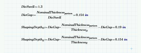
12 Die Design Die swell was assumed to be 1.3. Anand and Bhardwaj [14] found that the die swell of PP through a 5mm channel with a 10:1 L/D was around 1.8. However, we are using a glass fiber filled PP. Garcia-Rejon et al [15], found that adding glass fibers to HDPE reduced the diameter swell by 30%. Diameter swell was assumed to correlate roughly to thickness swell as thickness swell data was not given. Die swell of 1.3 was chosen for this project as it is about 70% of the 1.8 value obtained by Anand and Bhardwaj in order to allow for the glass fibers. The die/mandrel design includes the different shaping depth cuts used to achieve a fairly consistent nominal parison wall of about The nominal die gap used assuming a die swell of 1.3 was.154 To achieve consistent wall thickness six separate die shaping cuts were required. The calculated depth of the cuts for the corners (denoted in the calculations as ShapingDepthD) is and for the two outside edges the cuts are named ShapingDepthE and are However, as recommended in the Advanced Elastomer Systems EBM design guide [16] these calculated cut depths were reduced slightly to allow for the preferential flow of the polymer through the thicker regions of the die. Taking 70% of the calculated cut depths gives an actual cut depth of.143 for ShapingDepthD and.116 for ShapingDepthE. The die shaping calculations can be seen in the Appendix, Section 5. Images of the die model can be seen below. Design validation In the completion of this part design project there were not proper resources to completely fabricate and test a physical ladder. In place of physical testing, FEA simulation was run to determine if the design was feasible. The simulation helped to determine the ideal wall thickness which would be needed for the ladder to stand up to the requirements of the Type I ladder qualification test.


13 The simulation used a half model of the previously described Creo model of the ladder. A symmetry model was chosen instead of a full model to cut down on simulation time because the geometry of the ladder and loading condition is symmetric about the center plane. In the simulation an evenly distributed load of 400 lb was applied to a steel plate across the entire top step. This load simulates what would be an 800 lb load on the full width ladder during the OSHA Type I Ladder qualification testing. Other constraints are used on the feet of the ladder to prevent the ladder from moving away from the force. A constraint is also applied to simulate the steel ladder brace that will be present in the final assembly 16 inches below the top of the ladder and will prevent the ladder from simply splaying out and collapsing. The ladder brace was modelled with constraints instead of geometry for the simulation to save simulation time and because it is not expected to be a failure point due to the much higher strength of steel compared to polypropylene. The figure below shows the actual deflection of the ladder with a.050 inch wall thickness under a simulated 800lb load. The original position of the ladder is shown with a black line and the final position is shown by the colored model. The colors indicate distance from the original position. The max deflection of 1.7 inches is larger than the allowable deflection of 1 inch. In actual use, frictional forces on the feet of the ladder (not accounted for in the simulation) would help to prevent the ladder from splaying so badly. However, this functions as a safety factor to ensure that the ladder can support itself on slippery surfaces. An iterative process trying progressively thicker walls was used to come up with a wall thickness that would provide sufficient resistance to deflection without using unnecessary material. At the end, a 0.1 inch wall thickness was decided on. As can be seen in the image below, the feet of the ladder spread less than half the distance of the.05 inch wall thickness ladder


14 when the load is applied, a maximum deflection of 0.76 inches. This is acceptable as it is under the 1 inch limit. because the maximum occurs where a constraint is applied to an edge. The edge is the hole where the ladder brace is attached to the ladder. ANSYS can over predict the stress when forces or constraints are applied to sharp edges because they result in singularities where the stress concentration factor tends to cause results to go towards infinity. To get around this simulation shortcoming, the areas with singularities were omitted from the next plot. It was also important that the polypropylene would not pass its yield point when the test force was applied. A plot of the maximum equivalent stress was obtained from the simulation and compared to the tensile stress at break from the Celstran datasheet (shown in the Appendix, Section 2). Yield stress was not available and it was assumed that this was due to the very high modulus of the Celstran ( psi) causing yield and breakage to occur at almost the same point, meaning that the stress at break was effectively the yield stress. Material samples would have to be obtained and tested to check this. The simulation showed that the maximum equivalent stress caused by the 800lb load was 11,233 psi. This is a little less than the yield strength of psi. There is a certain amount of error in the simulated value for equivalent stress

15 The simulation highlighted the deep draws of the stairs to be over a 3:1 blow ratio which can be an issue in the blow molding process as the walls may thin too much. The plot of equivalent stress without the singularity regions indicates that the maximum stress on the ladder away from the hole region occurs in the region shown in red above and is about 3300 psi, well below the yield stress of psi. The conclusion drawn from the simulation is that a 0.1 inch wall thickness is required to obtain the necessary strength for the ladder to qualify as an OSHA Type I ladder. To further validate the design of the ladder a filling simulation was ran using the software Polyflow. By running a polyflow simulation some valuable results were obtained. The overall simulation was ran as a general troubleshooting or conformational simulation. The material data was set to a typical 30% glass filled polypropylene. In the running of the simulation some key results were gathered. The pictures following display area stretch plots which are essentially plots showing the blow ratio to different parts of the ladder. In this case it is advisable to keep the blow ratio to less than 3:1. The first picture is scaled to a blow ratio of 3:1 to help to highlight any problematic areas. The picture above shows an area stretch plot displaying the actual maximum blow ratio of the part. In this case it is approximately a 5:1 blow ratio. This most likely is due to how the pinch offs are configured causing the plastic to have to stretch much further. This may not be avoidable in the production but may be able to be combatted with parison programming.

16 Conclusion While considering the area stretch plot a more critical aspect is the wall thickness. The preceding picture displays the thickness plot representing the inherent wall thickness throughout the part. In this plot the areas in dark blue are the thinnest regions and are at a wall thickness of 0.15 which is slightly over the target nominal wall. This is due to trying to simulate pre blow in Polyflow and adjusting the wall thickness to try and hit a nominal value of The wall thickness of the parison could be further adjusted to create a more accurate simulation. This plot does an excellent job of displaying the gradient in wall thickness and how the further away from the pinch off the larger decrease in wall thickness. This plot also does a good job to show how the thinnest areas that will occur are in the deep corners of the stairs. The Polyflow was used as a trouble shooting technique and displayed how further modification of the mandrel and die could work to great effect in creating a consistent nominal wall. The front of the parison could be extruded thicker than the back half to help combat the large draw ratio the parison experiences. The simulation also further verifies the moldability of the product. Through simulation and research this project helped to show that an EBM ladder could be a cost effective alternative to a standard aluminum, wood, or fiberglass step ladder. The FEA analysis proved the ladder would be able to withstand the forces a Type I ladder would need to be able to hold up to. The analysis helped to determine the optimum wall thickness needed to stand up to the force which helped to reduce costs and cut down on the weight of the overall ladder. Future Improvements The design could be further improved by the production and testing of a prototype part. This would give a more realistic idea of the part s response to applied forces than the simulation. The design could also be altered to help reduce the blow ratio in the draws of the stairs which would also help with the nominal wall and ultimately the strength of the ladder. Acknowledgements Credit is due to Mr. Jon Meckley and Mr. Jason Williams of Penn State Erie for answering numerous questions regarding modelling the design in Creo Parametric and simulating the blow molding of the part using ANSYS Poyflow. Thanks also to Mr. David Johnson for his help with the use of ANSYS structural analysis software, used to simulate the Type I Ladder qualification testing. Finally, thanks is due to Glen Spiering, who rendered the 4ft ladder and another 3ft version to create the image below.

17
18 References [ DuPont, "Blow Molding Processing Manual," 1 DuPont Engineering Polymers, Switzerland, ] [ United States Department of Labor, 2 "Ladders Occupational Safety ] and Health Administration," Washington, [ S. Lane, "A14.5 Portable Reinforced Plastic 3 Ladders - American Ladder Institute," ] American Ladder Institute, [Online]. Available: age=a145standard. [Accessed 18 January 2017]. [ NOAA National Centers for Environmental 4 Information, "State of the Climate: National ] Climate Report for Annual 2015," NOAA National Centers for Environmental Information, January [Online]. Available: [Accessed 7 April 2017]. [ Grainger, "Are your ladders up to code?," 5 Grainger, [Online]. Available: ] [Accessed 7 April 2017]. [ Appalachian State University, "Ladder Saftey 6 Practices," Appalachian State University, 23 ] [Online]. Available: [Accessed 23 January 2017]. [ BestDeckSite, "Stairs & Railings," [Online]. Available: ] 2.htm. [Accessed 23 January 2017]. [ B. Riley, "FORMULA SAE ANTHROPOMETRIC 8 REFERENCE DATA 5TH PERCENTILE FEMALE ] &95TH PERCENTILE MALE," 23 November [Online]. Available: %20Rules95th_2016.pdf. [Accessed 23 January 2017]. [ The Center to Protect Workers Rights, 9 "Ladder Saftey," The Center to Protect ] Workers Rights, Silver Spring, [ Werner, "Fiberglass Ladder Technical 1 Manual," Werner, September [Online]. 0 Available: ] des/gm6070-fg-techmanual.pdf?sfvrsn=1. [Accessed 23 January 2017]. [ Electronic Library of Construction 1 Occupational Saftey and Health, "Hazard 1 Alert: Solvents in Construction," The Center ] for Construction Research and Training, [Online]. Available: Hazard%2BAlert%253A%2BSolvents%2Bin%2 BConstruction.html?show_text=1. [Accessed 23 January 2017]. [ GE Plastics, Engineered Blow Molding Part 1 Design, General Electric. 2 ] [ Clipper Controls, 1 " [Online]. 3 Available: ] chtalk-surface_finishes.pdf. [Accessed 02 March 2016]. [ J. S. Anand and I. S. Bhardwaj, "Die swell 1 behavior of Polypropylene, an experimental 4 investigation," Rheol. Acta, vol. 19, no. 5, pp. ] , 1980.
19 [ A. Garcia-Rejon, A. Meddad, E. Turcott and 1 M. Carmel, "Extrusion blow molding of long 5 fiber reinforced polyolefins," Polymer ] Engineering and Science, vol. 42, no. 2, pp , [ Chevron Phillips, Die shaping for extrusion 1 blow molding, The Woodlands, TX: Chevron 7 Phillips Chemical Company, LP, ] [ Advanced Elastomer Systems, Guide for 1 extrusion blow molding for thermoplastic 6 rubbers and thermoplastic elastomers, ] Advanced Elastomer Systems, 2001.
20 Appendix Section 1
21
22
23
24 Section 2

25
26
27

28 Section 3
29 Section 4

30 Note: The template shown below was developed by J. Meckley of Penn State Erie using equations from D. Kazmer.


31


32
33 Section 5 Note: For these calculations diagrams and equations were used from the Chevron Phillips Die Shaping Guide [17].
34


35