Single Mount Installation Instructions
|
|
|
- Brent Garrison
- 5 years ago
- Views:
Transcription

1 Single Mount Installation
2 Table of Contents Important Safety... 3 Configuration... 4 Package Contents... 4 Step 1 Determining Reference Height and Fastening... 5 Step 2 Ensuring Frame Structure is Straight and Plumb... 6 Step 3 Mounting Video Panel to Frame... 7 Warranty... 8 Video Wall Installation Manual V155, V170, V180 Page 2
3 Important Safety CAUTION: Before you begin any of the installation procedures read and follow the warnings and important safety instructions within the manual. WARNING! FAILURE TO FOLLOW INSTRUCTIONS ON ACCESSING BEHIND PANELS AND SERVICING PANELS MAY RESULT IN POSSIBLE PERSONAL INJURY AND DAMAGE TO VIDEO PANELS DUE FROM FALLING! WARNING! BEFORE INSTALLING THE MOUNT, ENSURE THE WALL IS STRUCTUALLY SOUND AND ABLE TO PROPERLY SUPPORT THE COMBINED WEIGHT OF MOUNT AND VIDEO PANELS! Use the following safety guidelines to help protect you during the installation, especially with installing the video panels to mount and when access to panels is required to ensure your own personal safety. Read all the installation instructions before installing the mounting solution. Read and follow all important safety instructions. Depending on size of video mount solutions, two (2) or more persons may be required for installation. Please ensure all safety precautions are followed when working with heights. Video Wall Installation Manual V155, V170, V180 Page 3
4 Model and Specifications Product V155 V170 V180 Orientation Landscape or Portrait Screen Sizes 55 to to to 95 Dimensions 1134 x 508 x x 610 x x 762 x 69 (WXHXD) mm TV Weight Max 80kg 120kg 140kg Panel VESA Mounts Wall Mounting Brackets VESA Security Lock Wall Stiffer Required? Kick Stand Colour Fully Assembled Included Included All VESA and non VESA configurations Included No Included (Device Used to Tilt Panels For Servicing or Access at Back) Aluminum with Black Side Rails Yes Video Wall Installation Manual V155, V170, V180 Page 4
 1W X 1H 2 Part D Mounting Hardware Kit 1W X 1H 1 Part F Kick Stand 1W X 1H 1 Part KS Monitor Security Lock 1W X 1H 1 Part SL Video Wall Installation Manual V155,")
5 Package Contents - Included Description Configuration Qty Picture Preassembled Frame with wall brackets (May include a middle rail depending on screen size) 1W X 1H 1 Part A Panel VESA Bracket (includes micro adjustment screw) 1W X 1H 2 Part D Mounting Hardware Kit 1W X 1H 1 Part F Kick Stand 1W X 1H 1 Part KS Monitor Security Lock 1W X 1H 1 Part SL Video Wall Installation Manual V155, V170, V180 Page 5
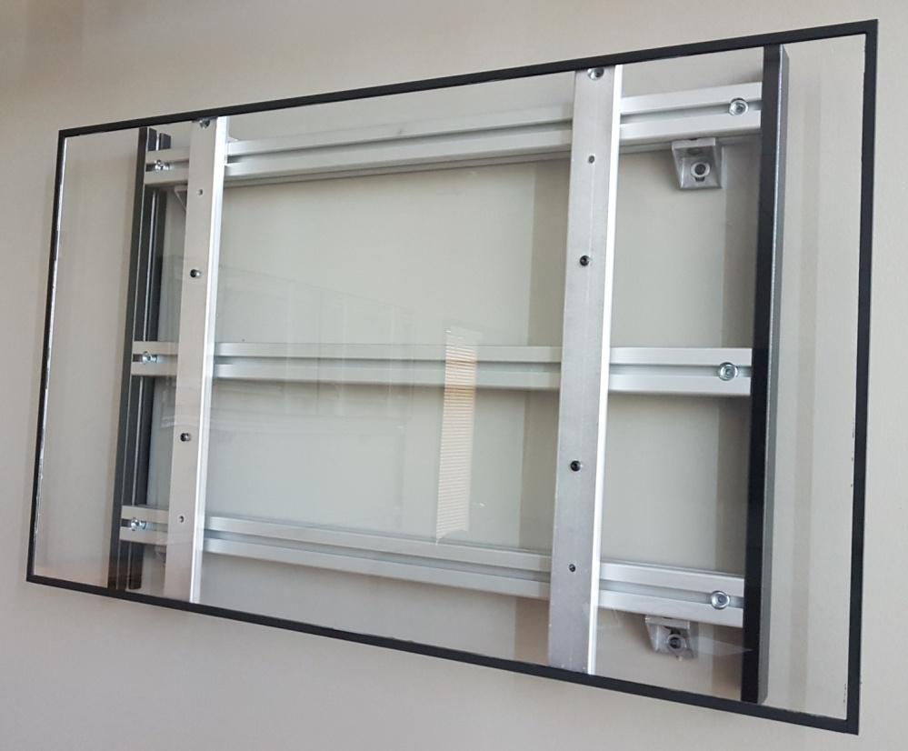
6 Step 1 Determining Reference Height and Fastening a) Measure the total length of video wall mounting frame in order to determine center point for wall installation. Take total length / 2 to determine center point. Determining center point for video wall. b) Mark wall with centre point. c) Mark wall with outside measurements of video wall as shown in figure 4A. d) Level and fasten mount to wall. (Fastening hardware not included) For wood or metal studded walls only Determine location of all wall studs that are behind video wall and mark each stud accordingly using stud finder. For concrete or concrete block walls only Depending on number of Wall Brackets (Part E) supplied, determine placement by evenly spacing them out Fig. 4A Video Wall Installation Manual V155, V170, V180 Page 6

7 Step 2 Ensuring Frame Structure is straight and plumb IMPORTANT: It is extremely important the frame structure is straight along the entire length of structure and plumb the entire length down the wall. Do not push the frame structure against the wall. The frame structure is designed to act as the support structure for the panel and not the wall itself. a) Almost all walls are not build straight you will need to use a laser level to ensure the frame structure is straight along the entire length of structure. See figure 6A. b) In the event a portion of horizontal section needs to be adjusted slightly inwards or outwards the Wall Brackets do have a slot to allow for these adjustments. See figure 6B. Fig. 6A c) Once the frame structure is straight, plum and level tighten each Bolt to secure and lock frame the frame in position. Tighten the loose Bolts at Wall Bracket once frame is straight horizontally and vertically Fig. 6B Video Wall Installation Manual V155, V170, V180 Page 7
. Note: If video panel orientation is portrait mode attach Panel VESA Brackets to back of video panels with that orientation.")
8 Step 3 Attaching Mounting Brackets a) Remove video display panel to be installed from carton and attach the Panel VESA Brackets (Part D) to back of panels at the VESA mounts as shown in figure 1A. Mounting hardware is provided (Part F). Note: If video panel orientation is portrait mode attach Panel VESA Brackets to back of video panels with that orientation. b) The mounting hardware consists of various lengths of M6 and M8 screws to accommodate different manufacturer specifications. c) If M6 screws are required, you will need to use the white M8 sleeves by inserting an M6 screw into the white sleeve and then attaching Panel VESA Bracket to back of video panel. See figure 1B. Fig. 1A Fig. 1B Video Wall Installation Manual V155, V170, V180 Page 8

 To mount video panel, lift and slightly tilt panel then insert the downward pointing tab at top of each Mounting Bracket into the T-slot at top of rail.")
 Once video panel is mounted to rail it can be moved sideways by simply along the rail. Fig. 7B Fig. 7C Fig.")
9 Step 4 Mounting Frame Structure IMPORTANT: Before mounting any video panel recheck to ensure all hardware has been tighten with hex Allen keys to prevent any physical damage to video panel falling or personal injury. a) In previous Step 3, the Panel VESA Brackets (Part D) should have been attached to back of video panel at the VESA mount locations. Fig. 17 b) To mount video panel, lift and slightly tilt panel then insert the downward pointing tab at top of each Mounting Bracket into the T-slot at top of rail. See figures 7B and 7C. c) Make sure both Panel VESA Brackets are inserted properly otherwise video panel may fall. See figure 7D. d) Once video panel is mounted to rail it can be moved sideways by simply along the rail. Fig. 7B Fig. 7C Fig. 7D IMPORTANT In the event panel do not mount correctly on frame, the most common cause is result of frame not mounted level and plumb. If you still need assistance with the installation, we are a phone call away at (905) Video Wall Installation Manual V155, V170, V180 Page 9
 Place one Monitor Security Lock on either the left or right Top Panel Clamp. See Figure 9A.")
 screws. See Figure 9B. Fig. 9A Fig.")
 provided.")
10 Step 4 Installing Monitor Security Lock (Optional) The Monitor Security Lock is only required to be fastened to top of monitor on rail. a) Place one Monitor Security Lock on either the left or right Top Panel Clamp. See Figure 9A. b) Once the Monitor Security Lock has been positioned directly on top of panel clamp, secure the lock by tightening the two (2) screws. See Figure 9B. Fig. 9A Fig. 9B Step 5 Accessing behind Panel and Servicing Panel a) To gain access behind panel you will require the use of Kick Stand (Part KS) provided. To insert Kick Stand simply tilt bottom of panel and ensure locking tab is inserted into top slot of each bottom rail. See figure 5A. Fig. 5A Video Wall Installation Manual V155, V170, V180 Page 10
11 Warranty Micron Display Solutions ( MICRON ) warrants to the first purchaser for this product ( Product ), when shipped in its original container and sold or distributed in Canada by Micron or by an authorized Micron dealer, and Product was not sold as is or sales final that the Product will be free from defects in material and workmanship for a period of three (3) years and will within the warranty period, either repair the defective Product or provide the purchaser a replacement of the defective Product. This warranty does not apply to any appearance items of the product nor to the exterior of which has been damaged or defaced, which has been subjected to improper voltage or other misuse, abnormal service or handling, which has been altered or modified in design or construction, or if the serial number or model number affixed to Product has been removed, defaced, changed, altered or tampered with. Micron Display Solutions 2679 Bristol Circle, Unit 6 Oakville, Ontario L6H 6Z8 (905) Video Wall Installation Manual V155, V170, V180 Page 11