Park Potomac Office Building E
|
|
|
- Claribel Morgan
- 5 years ago
- Views:
Transcription
1 Technical Assignment 1 Kyle Wagner (IP) AE Consultant: Professor Kevin Parfitt October 05, 2009
2 Table of Contents I. Executive Summary 3 II. Introduction... 4 III. Structural System Overview Foundation 4 Superstructure 5 IV. Codes and Design Standards 9 V. Building Load Summary 11 Gravity. 11 Wind 13 Seismic 18 Spot Checks 23 VI. Appendices. 27 A: Wind 27 B: Seismic 36 C: Spot Check Calculations. 46 D: Photos
3 Executive Summary: This report outlines the existing conditions of. This office building is a new addition to the recent community at Park Potomac in Potomac, MD. Office Building E is a seven story building with two large levels of below grade parking. Above grade, post tensioned concrete is prevalent, with beams and slabs spanning in each direction for all floors. This rigid building is designed using ordinary concrete moment frames to resist lateral forces in both directions, as well as to carry gravity loads. Several different types of loadings were examined in this report. First, live loads, superimposed dead loads, and flat roof snow loads were calculated using ASCE These loads were all found to be similar to the design loads used. Wind loads were calculated for the building as well. Wind pressures, story forces and shears, and overturning moments were found in both directions due to wind loading. Wind forces in the East West direction were found to control due to a larger surface area on the East and West building facades. Wind analysis revealed a base shear of 468K and an overturning moment of ft k. Seismic analysis by the structural engineer yielded a base shear of 300K in the design. The seismic analysis in this report was not as accurate due to some overly conservative assumptions made early in the seismic design. Differences in calculation of overall building weights may have also played a role in the discrepancies between the base shears. Also included in this report is a spot check of a column and a floor slab from Office Building E. A sixth floor column was first analyzed to determine the interaction diagram for axial and bending forces. The scope of this report required an analysis of the gravity loads only on the column. The column strength was more than adequate for the 690K axial load on the column. This additional strength will be important in the next phase, when lateral loads as well as axial loads are considered. The spot checks on the building also included a spot check of the two way reinforced P1 Parking Level slab as well. These calculations showed very low moments on the bay selected, resulting from short 13 spans, as well as longer, thinner columns. This limited the required reinforcement from the analysis, which was reflected in the actual design

4 Introduction: is located prominently off I 270 at Seven Locks and Montrose Roads. It is just one of several planned office buildings that are part of an urban village which mixes stunning town homes, Class A office space, and a wide range of amenities including dining and shopping. Office Building E is a central part of the Park Potomac Master Plan. Its central location, at the end of Cadbury Avenue, makes it a focal point for this small community (Figure 1). It also puts it right at the main courtyard that will be a retail gathering point as well. Figure 1: View from Cadbury Ave. Structural System Overview Foundations: consists of a seven story office building that sits above two levels of underground parking. The parking structure levels have a footprint of over 103,000 sq. ft. This is much larger than the office structure, which has a footprint of just more than 25,000 sq. ft. This relationship has a large impact on the design of the foundation as well. The net allowable bearing pressures for the site are 4000 psi for undisturbed soil and 3,000 psi for foundations place on compacted structural fill. Over 150 spread footings are used throughout the project (Figure 2). All footings are 3000 psi concrete, and foundation walls are 4000 psi concrete. Spread footings, mostly ranging from 10 x 10 to 12 x 12, are used beneath the two levels of parking with no office building above. The majority of these footings are between 28 and 34 deep

5 Larger footings are used in the center of the project, taking load from the two parking levels and also from the office building above. These larger foundations are up to 52 x 64 in size and can be up to 62 deep. Figure 2: Foundation Plan Superstructure: Floor system: The slab on grade at the P2 Parking Level is a 5 thick, 3500 psi concrete slab. It is reinforced with 6x6 W2.0 x W2.0 welded wire fabric. All other slabs contain 5000psi concrete. Two way flat slabs are used at the P1 Parking level and the Plaza/First Floor Level as well. The slab is 8 thick at the P1 Level and 12 thick at the Plaza/First Floor Level. These slabs are reinforced as needed to resist negative moment at the columns and positive moments at midspan. Post tensioning is not used on the parking levels. Tying a post tensioned slab into foundation walls or other fixed structure does not allow the post tensioned slab to shrink when stressed. This would result in cracking of the slab if post tensioning was used below grade. Using this method for the parking garage 5 5 6
6 would also lead to difficulty in stressing the tendons as well. The designers of Office Building E use mild reinforcing below grade, and post tensioning for the slabs above grade. Above the Plaza Level, Office Building E has seven levels of office floors. These floors are 7 thick post tensioned slabs. The post tensioning cables are 3.5 in diameter and induce forces in the slab ranging from 12.5 k/ft up to 35 k/ft. The post tensioning system uses banded tendons in the beams in the E W direction, and a one way slab with uniform tendon layout in the N S direction. This design allows for ease of construction when laying out the tendons. The post tensioned slab also allows for cantilevers that exist at the North and South ends of the structure. The load from a 12 cantilever on each end is taken by the uniformly spaced tendons that run through the slab. Post tensioning is key to achieving several main goals on this project. The first main goal is that it allows for large spans in the floor layout. The design of this project requires that columns be placed around the exterior walls of the building and the interior core as well. This requires the beams and slab to span long distances over the floor. Post tensioning achieves these span requirements while maintaining a slab thickness of just 7 inches. Deflection over these spans is controlled effectively, while cracking is reduced as well. Several steel shapes are utilized on the second floor slab to frame out the canopies above the East and West building entrances. This framing consists of TS5x2 shapes that are welded to ¾ plates and hung from the bottom of the slab by L4x4 angles. Steel shapes (W8x10) are also utilized as elevator rail supports throughout all floors
7 Gravity System: Figure 3: Typical Framing Plan The majority of the columns in the two levels of parking are 18 x 36 columns reinforced with 10 #9 bars. These columns are typically spaced between 15 and 30 apart. Columns supporting only the two parking levels consist of 4000 psi concrete, while 6000 psi concrete is utilized where load from the office building portion above is carried. Columns in the parking levels utilize drop panels to spread the load and resist punching shear. In the office portion of the project, a relatively repetitive column layout is achieved. Excluding the central building core, 32 columns are used to transfer the load down through all seven levels. Long span post tensioned beams are used to transfer load from the floor to the columns. At typically 20 x 72 in size, these shallow, wide beams span in the E W direction and continue the entire building width. In order to minimize the amount of columns in the tenant spaces and promote flexible space planning, large spans up to nearly 45 exist on each floor
8 Columns on the office levels are 24 x 24 at every level and the concrete strength is varied throughout the levels to support an increased load as required. The plaza level through the fourth floor use 5000 psi concrete, while 4000 psi concrete is used above the fourth floor. Lateral System: uses concrete moment frames to resist lateral forces. In the E W direction, the wide post tensioned beams on each floor create a series of parallel frames that run up through all seven floors. These frames resist any lateral forces on the building in the parallel direction. Similarly, forces in the N S direction are resisted essentially by concrete moment frames as well. The concrete columns and the 7 slab, which is post tensioned in the N S direction, combine to create a frame that resists later forces in this direction as well. In both directions, the lateral forces are taken by the slab or beams and is transferred to the columns and down through the building. Roof System: The main roof system consists of a 7 to 8 structural slab. This slab varies in order to create the required roof slopes throughout. The roof contains a Penthouse/Mechanical space, as well as an elevator machine room. The penthouse roof is an 8 two way flat plate system, while the elevator machine room utilizes a 12 thick slab. TS8x8 posts and TS 6x6 supports are used to frame a 16 tall screen wall on the roof level to isolate the mechanical spaces from view
9 Codes & Design Standards: Original Design: a. The International Building Code 2003, International Code Council b. Minimum Design Loads for Buildings and Other Structures (ASCE7), American Society of Civil Engineers c. Building Code Requirements for Structural Concrete, ACE , American Concrete Institute d. ACI Manual of Concrete Practice Parts 1 Through 5, American Concrete Institute e. Manual of Standard Practice, Concrete Reinforcing Steel Institute f. Post Tensioning Manual, Post Tensioning Institute g. Manual of Steel Construction Allowable Stress Design, Ninth Edition, 1989, American Institute of Steel Construction (Including specifications for structural steel buildings, specifications for structural joints using ASTM A325 of A490 bolts and AISC Code of Standard Practice) Substituted for thesis analysis: a. The International Building Code 2006, International Code Council b. Minimum Design Loads for Buildings and Other Structures (ASCE7), American Society of Civil Engineers c. Building Code Requirements for Structural Concrete, ACI , American Concrete Institute 9 5 6
10 Material Strength Summary: Concrete: Footings Foundation Walls Columns Slab on Grade Reinforced Slabs & Beams Parking Structure P.T. Concrete 3000 psi 4000 psi Varies 3500 psi 5000 psi 5000 psi 5000 psi Structural Steel: Wide Flanges & Tees ASTM A992, Fy = 50 ksi Square/Rectangular Hollow Shapes ASTM A500, Grade B, Fy = 46 ksi Masonry: Compressive Strength 1500 psi
11 Gravity Loads: Floor live loads were determined using ASCE These loads were then compared to the design loads used in the original design. The design loads were largely the same as those from ASCE A few of the loads used exceeded the required loadings from ASCE These loads can be found below. Table 1: Floor Live Loads Area Design Load (psf) ASCE 7 05 Load (psf) Assembly Areas Corridors Corridors Above First Floor Lobbies Marquees & Canopies Mechanical Rooms Offices psf Partitions 50 Parking Garages Plaza, Top Floor Parking Fire Truck Load or 250 psf 250 Retail First Floor Stairs and Exitways Storage (Light) The following superimposed dead loads were also considered in the design of the structure. Table 2: Superimposed Dead Loads Area Design Load (psf) Floors 5 Roof
12 A flat roof snow load was calculated for this report as well. Beginning with a 30 psf ground snow load for Montgomery County, a flat roof snow load of 21 psf was calculated using the variables shown below from ASCE This snow load of 21 psf was identical to the design snow load used by Cagley & Associates. Snow drift was not considered in this report, but will be analyzed more closely in future technical reports. Table 3: Flat Roof Snow Load Ground Snow Load P g = 30 psf Snow Exposure Factor C e = 1.0 (Terrain Category B) Thermal Factor C t = 1.0 Importance Factor I= 1.0 Flat Roof Snow Load p f 21 psf
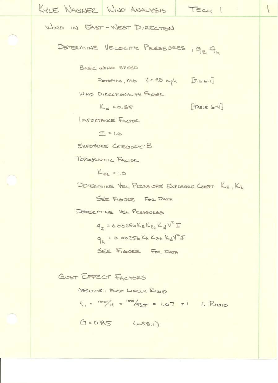
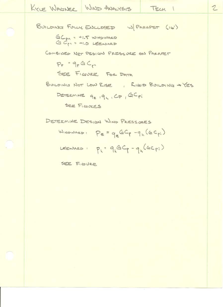
13 Wind Loads: Method 2, detailed in Chapter 6 of ASCE 7 05, was used to determine the wind loading for the building. Wind loadings in the N S and the E W directions were both analyzed. Detailed calculations can be found in Appendix A of this report. The analysis revealed the uniform pressures that occurred due to wind, which allowed the base shears and overturning moments to be determined as well. In the E W direction, the parking levels are completely below grade. The entrance is at the Plaza Level on the East and West sides of the building. This is reflected in the analysis. Roof uplift forces were not considered in this analysis. Results and loading diagrams can be found below. Level Height (ft above Plaza) Table 4: East West Design Pressures Design Design Total Pressure Pressure Pressure Windward Leeward (psf) (psf) (psf) Force of Total Pressure (k) Story Shear Total (k) Moment Windward (ft k) Plaza Level nd Floor rd Floor th Floor th Floor th Floor th Floor Main Roof Penthouse Base Shear 468 K Overturning Moment ft k
14 Figure 4: East West Design Pressures
15 Analysis results for the N S wind direction can be found below. The parking level was not considered in this analysis because it was assumed that the wind would be totally blocked by the existing grade due to the site layout at these locations. Results and loading diagrams can be found below for the N S wind direction. Level Height (ft above Plaza) Table 5: North South Design Pressures Design Pressure Windward (psf) Design Pressure Leeward (psf) Total Pressure (psf) Force of Total Pressure (k) Story Shear Total (k) Moment Windward (ftk) Plaza Level nd Floor rd Floor th Floor th Floor th Floor th Floor Main Roof Penthouse Base Shear 236 K Overturning Moment ft k
16 Figure 5: North South Wind Pressures Clearly, by analyzing the base shears and overturning moments in both directions, it is evident that the wind in the E W direction is the most critical for the existing building. The base shear in this direction is 468 K, compared to only 236 in the N S direction. The overturning moment reflects this relationship as well, with the E W moment exceeding the other direction by nearly a factor of two. This seems to make sense due to the larger surface area on the West and East faces of the building. These sides are about 225 in width, while the North and South faces are only around 125. This is in line with the results obtained in this analysis. The wind pressures obtained in this analysis result in forces that act at each story. These loads are transferred from the building façade by tributary area and act on the floors, which are considered rigid, and into the moment frames in both directions. These frames use columns, as well as the post tensioned beams and slab to resist lateral forces in both directions
17 The wind design variables that were available were consistent with the variables used in this analysis. The final design forces, however, were not available for direct comparison

18 Seismic Analysis: The layout of the parking levels, and the surrounding ground, created unique seismic considerations for Office Building E. The two levels of underground parking were mostly below grade, except on the North side of the structure. This scenario can be seen below. Figure 6: View from North In the figure, it is evident that on the North side, the structure is not braced by the ground. This is not the case for the other sides. Along the East and West, the parking is completely below grade and the parking is braced by the ground on each side. In order to account for this exposure on the North side, and after consulting a member of the AE Faculty, a conservative assumption was made to deal with this problem. For the seismic analysis in this report, it was assumed that the parking levels were completely exposed for lateral loads in the N S direction. For loads in the E W direction, the parking levels were almost completely below grade. For this direction, only the seven stories above grade were considered for analysis
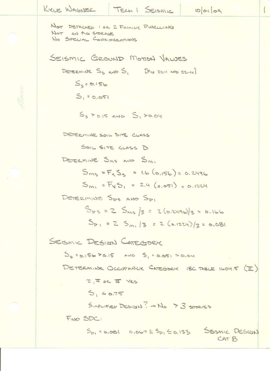
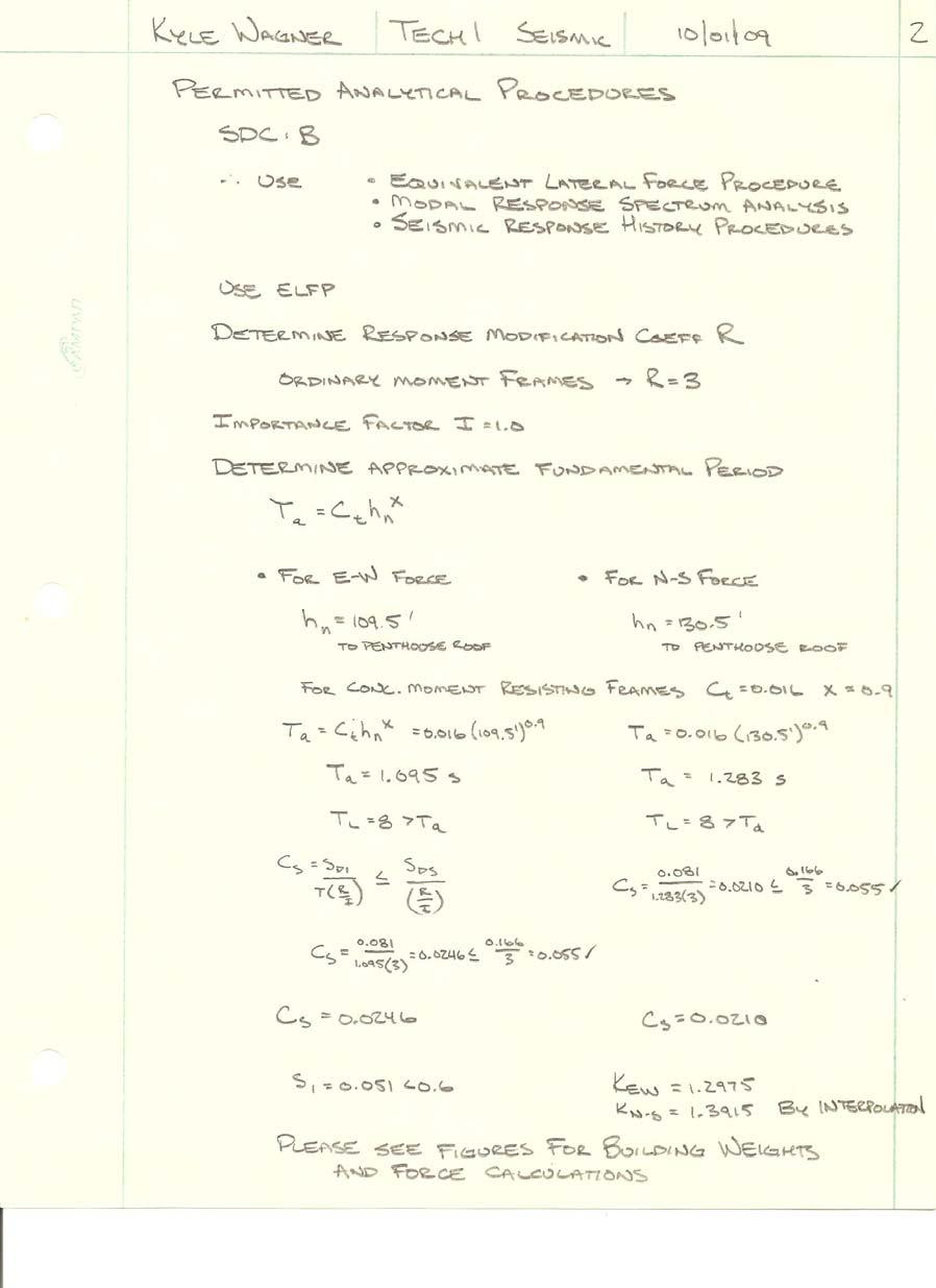
19 The seismic analysis in this report was completed using Chapters 11 and 12 from ASCE The equivalent lateral force procedure was determined to be valid for this analysis. Detailed calculations, including building self weights and other variables are available in Appendix B. The main variables used in the analysis are shown below. Table 5: Seismic Design Variables ASCE Reference Soil Classification D Table Occupancy II Table 1 1 Importance Factor 1.0 Table Structural System Ordinary Moment Frames Table Spectral Response Acceleration, Short S s USGS Website Spectral Response Acceleration, 1 s S USGS Website Site Coefficient F a 1.6 Table Site Coefficient F v 2.4 Table MCE Spectral Response Acceleration, Short S MS Eq MCE Spectral Response Acceleration, 1 s S M Eq Design Spectral Acceleration, Short S DS Eq Design Spectral Acceleration, 1 s S D Eq Seismic Design Category S DC B Table Response Modification Coefficient R 3 Table Approximate Period Parameter C t Table Building Height (E W) h n 109.5' Building Height (N S) h n 130.5' Approximate Period Parameter x 0.9 Table Approximate Fundamental Period (E W) T a s Eq Approximate Fundamental Period (N S) T a s Eq Long Period Transition Period T L 8.0 s Fig Seismic Response Coefficient (E W) C s Eq Seismic Response Coefficient (N S) C s Eq Structure Period Exponent k 1.0 Sec After calculation of the overall building self weight (See Appendix B), base shears can be calculated in order to calculate the forces on the structure. These base shears are shown below in Table 6. The large difference between the two directions is the fact that the
20 parking levels self weight was considered in the North South analysis. This resulted in a vast difference in the building weights used for each case. Effective Seismic Weight Table 6: Base Shears Seismic Response Coefficient Base Shear (K) N S W = K Cs = E W W = K Cs = After the calculation of the base shear values for each direction, the forces can be distributed throughout the building to determine forces at each level, story shear values, and overturning moments. Level Story Weight (K) Table 7: Seismic Calculations N S Height (ft) E W Height (ft) N S Forces (K) Fx E W Forces (K) Fx N S Story Shear Vx E W Story Shear Vx N S Moments (ft k) Mx E W Moments (ft k) Mx Penthouse Roof Main Roof th Floor th Floor th Floor th Floor rd Floor nd Floor Plaza/First Floor P1 Level* P2 Level/Foundation* Total:
21 Figure 7: East West Seismic Forces
22 Figure 8: North South Seismic Forces The seismic analysis competed by the structural engineer yielded a base shear of only 300K. This is a large difference from the values obtained in this analysis. This is especially true in the N S direction, which yielded a base shear of just over 1500 K. The conservative assumption used to deal with the site layout appears to have been overly conservative. This is clear when analyzing the building weights used in both directions. The inclusion of the parking structure in the building weight for the analysis in the N S direction added almost Kips to the total weight. This is enormous, especially considering that the building weight for the E W analysis was K total. This extreme addition was mostly due to the parking level slabs, which covered around 110,000 sq. ft. a piece, and were up to 12 thick. It is likely that other discrepancies between the calculations were due to the calculation of the building self weight. All variables found were consistent with those used by the structural engineer; however, the building self weights used by the structural engineer were not available for confirmation. It is likely that this is where the differences existed. It is clear that less conservative assumptions were made by the structural engineer, which led to much lower base shears, as well as story forces and moments

23 Spot Checks: Column at H 2: The first spot check completed for this report was a check of the sixth floor column in the office building portion of the building. This column was at gridlines H 2. The tributary area was 1008 sq. ft. and can be seen on Figure 9 below. Figure 9: Column at H 2 Grid Several calculations were performed on this column to determine it capacity for axial as well as bending forces. These calculations are available in Appendix C. After calculating M n and P n at numerous loadings, an interaction diagram was drawn for the column. These forces and the interaction diagram are below. Table 8: Column Spot Check Mn (ft k) Pn (k)
24 2500 Pn vs. Mn for Column at H Pn Figure 10: Column Interaction Diagram Considering axial forces only, the column is more than adequate for the 690K required from it. This is also clear from looking at the interaction diagram as well. This report does not take into account the bending forces on the column. In reality, the lateral loads on the building will induce moment in each of the columns. As these columns resist moment, they are stressed further towards their failure point. This interaction diagram will be analyzed further as the moments are calculated from the lateral loads in further reports
25 Two Way Slab: The P1 Level slab was also analyzed in this report as well. A 13 x 28 bay, between gridlines 7P 8P and FP GP was examined to check the reinforcing in the slab. This section of the 8 thick slab was an interior bay supported by 18 x 36 columns. It is seen below in Figure 10. Figure 10: P1 Level Slab Portion In the analysis, a slab dead load of 100 psf and a garage live load of 40 psf were used, which yielded a 200 psf ultimate load. Upon checking the slab thickness with ACI 318 deflection control limits (Table 9.5c) I found that the slab thickness did not comply with these requirements. Therefore, deflections calculations would have to be done on this slab to ensure that the deflection was adequate. Also, upon calculation and distribution of moments along the frames in this analysis, it was found that the moments were extremely small in the vertical direction. This is due mainly to the 13 span distance, as well as the columns being in a longer orientation in the vertical direction. This yielded small amounts of reinforcement in that direction, which is consistent with the design of the slab. More detailed calculations can be found in Appendix C. No spot checks were performed on the post tensioned slabs or beams due to the fact that a gravity only analysis of these members would yield insignificant results due to the
26 fact that these post tensioned members are largely responsible for resisting lateral forces. These members will be examined more closely in the next technical reports as the lateral loads on the structure are more closely considered
27 Appendix A: Wind
28 28 5 6
29 29 5 6
30 Table 9: E W Basic Wind Analysis Factors Exposure B Case 2 L (Most conservative) = ft B= ft L/B= Basic Wind Speed V= 90 Wind Directionality Factor K d = 0.85 Importance Factor I= 1.0 Exposure Category Category B Topographical Factor K zt = 1.0 Gust Effect Factor G= 0.85 Cp Windward C p = 0.8 Cp Leeward C p = 0.5 G cpi Windward 0.18 G cpi Leeward 0.18 GC pn Windward 1.5 GC pn Leeward 1 Table 10: E W Velocity Pressure Exposure Coefficients, Kh and Kz Level Height (ft above Plaza) Kz, Kh, Kp qz, qh, qp Windward qz, qh Leeward Plaza Level nd Floor rd Floor th Floor th Floor th Floor th Floor Main Roof Penthouse Level
31 Height (ft above Plaza) Table 11: E W Calculation of Design Wind Pressures Windward External External Net Net Pressure Pressure Internal Pressure Pressure Windward Leeward Pressure P Pos P Neg (psf) (psf) (psf) (psf) (psf) Net Pressure P Pos (psf) Leeward Net Pressure P Neg (psf) Level Plaza Level nd Floor rd Floor th Floor th Floor th Floor th Floor Main Roof
32 Level Height (ft above Plaza) Design Pressure Windward (psf) Table 12: E W Design Pressures Design Pressure Leeward (psf) Total Pressure (psf) Force of Total Pressure (k) Story Shear Total (k) Moment Windward (ft k) Plaza Level nd Floor rd Floor th Floor th Floor th Floor th Floor Main Roof Penthouse East West Direction Base Shear K Overturning Moment ft k
33 Table 13: N S Basic Wind Analysis Factors Exposure B Case 2 L (Most Conservative)= ft B= ft L/B= Basic Wind Speed V= 90 Wind Directionality Factor K d = 0.85 Importance Factor I= 1 Exposure Category Category B Topographical Factor K zt = 1 Gust Effect Factor G= 0.85 Cp Windward C p = 0.8 Cp Leeward C p = 0.35 G cpi Windward 0.18 G cpi Leeward 0.18 GC pn Windward 1.5 GC pn Leeward 1 Table 14: N S Velocity Pressure Exposure Coefficients, Kh and Kz Level Height (ft above Plaza) Kz, Kh, Kp qz, qh, qp Windward qz, qh Leeward Plaza Level nd Floor rd Floor th Floor th Floor th Floor th Floor Main Roof Penthouse Level
34 Height (ft above Plaza) Table 15: N S Calculation of Design Wind Pressures Windward External External Net Net Pressure Pressure Internal Pressure Pressure Windward Leeward Pressure P Pos P Neg (psf) (psf) (psf) (psf) (psf) Net Pressure P Pos (psf) Leeward Net Pressure P Neg (psf) Level Plaza Level nd Floor rd Floor th Floor th Floor th Floor th Floor Main Roof
35 Level Height (ft above Plaza) Table 16: N S Design Pressures Design Pressure Windward (psf) Design Pressure Leeward (psf) Total Pressure (psf) Force of Total Pressure (k) Story Shear Total (k) Moment Windward (ft k) Plaza Level nd Floor rd Floor th Floor th Floor th Floor th Floor Main Roof Penthouse North South Direction Base Shear K Overturning Moment ft k
36 Appendix B: Seismic
37 37 5 6
38 38 5 6
39 Level Table 17: Basic Building Information Height Above Floor Floor Area (SF) Plaza (in) Distance (ft) Slab Thickness (in) Penthouse Roof Main Roof th Floor th Floor th Floor th Floor rd Floor nd Floor Plaza/First Floor P1 Level* P2 Level/Foundation* * Parking Ramp Excluded Table 18: Penthouse Level Self Weight (Assume Elevator Room at 16': Conservative) Slabs: Penthouse 200 K Elevator Machine Room 95 K Superimposed Dead 10 psf 263 K Penthouse Total: 557 K
40 Table 19: Roof Self Weight Slabs: Main Roof Slab 2306 K PT Beam Weight: 879 K Primary Column Weight: (32) 24" x 24" Columns 125 K Superimposed Dead: 10 psf 264 K Building Core: (12) 12x24 Columns 23 K Core Beams (12" x 30") 17 K Core Beams (12" x 24") 24 K Core Beams (12" x 20") 22 K Building Envelope: 15 psf Assumed 62 K Mechanical: AHU (2 units) 127 K Cooling Tower 6 K AC Unit 4 K Roof Total: 3858 K Table 20: Level 7 Self Weight Slab Weight: 7" Thick Slab 2306 K PT Beam Weight: 879 K Primary Column Weight: (32) 24" x 24" Columns 245 K Superimposed Dead: 5 psf 131 K Building Core: (12) 12" x 24" Columns 46 K Core Beams (12" x 30") 17 K Core Beams (12" x 24") 24 K Core Beams (12" x 20") 22 K Building Envelope: 15 psf Assumed 122 K Level 7 Total: 3792 K
41 Table 21: Levels 3 6 Self Weight Slab Weight: 7" Thick Slab 2299 K PT Beam Weight: 879 K Primary Column Weight: (32) 24" x 24" Columns 240 K Superimposed Dead: 5 psf 131 K Building Core: (12) 12" x 24" Columns 45 K Core Beams (12" x 30") 17 K Core Beams (12" x 24") 24 K Core Beams (12" x 20") 22 K Building Envelope: 15 psf Assumed 120 K Level 3 6 Total: 3777 K Per Floor Table 22: Level 2 Self Weight Slab Weight: 7" Thick Slab 2299 K PT Beam Weight: 879 K Primary Column Weight: (32) 24" x 24" Columns 293 K Superimposed Dead: 5 psf 131 K Building Core: (12) 12" x 24" Columns 55 K Core Beams (12" x 30") 17 K Core Beams (12" x 24") 24 K Core Beams (12" x 20") 22 K Building Envelope: 15 psf Assumed 120 K Level 2 Total: 3840 K
42 Table 23: Plaza/Ground Level Self Weight Slab Weight: 12" Thick Slab K Columns Above: (32) 24" x 24" 173 K Columns Below: (16) 12" x 24" 26 K (163) 18" x 36" 605 K (19) 24" x 24" 63 K (4) 24" x 30" 17 K (5) 24" x 42" 29 K (4) 28" x 45" 29 K (4) 30" x 72" 50 K (1) 39" x 36" 8 K Drop Panels: (225) 10' x 10' x 5.5" 1547 K Building Core: Core Beams (12" x 30") 17 K Core Beams (12" x 24") 24 K Core Beams (12" x 20") 22 K Building Envelope: 15 psf Assumed 86 K Plaza/Ground Total: K
43 Table 24: P1 Parking Level Self Weight Slab Weight: 8" Thick Slab K Columns: (16) 12" x 24" 50 K (163) 18" x 36" 1155 K (19) 24" x 24" 120 K (4) 24" x 30" 32 K (5) 24" x 42" 55 K (4) 28" x 45" 55 K (4) 30" x 72" 95 K (1) 39" x 36" 15 K Drop Panels: (225) 10' x 10' x 5.5" 1547 K Building Core: Core Beams (12" x 30") 17 K Core Beams (12" x 24") 24 K Core Beams (12" x 20") 22 K Level P1 Total: K Table 25: P2 Parking Level Self Weight Columns: (16) 12" x 24" 24 K (163) 18" x 36" 550 K (19) 24" x 24" 57 K (4) 24" x 30" 15 K (5) 24" x 42" 26 K (4) 28" x 45" 26 K (4) 30" x 72" 45 K (1) 39" x 36" 7 K Level P2 Total: 751 K
44 Total Building Weight (N S): Total Building Weight (E W): K K Effective Seismic Weight Table 26: Base Shears Seismic Response Coefficient Base Shear (K) N S W = K Cs = E W W = K Cs =
45 Table 27: Seismic Calculations N S Story Shear E W Story Shear Level Story N S Height E W Height N S Forces E W Forces N S Moments E W Moments Weight (K) (ft) (ft) (K) Fx (K) Fx Vx Vx (ft k) Mx (ft k) Mx Penthouse Roof Main Roof th Floor th Floor th Floor th Floor rd Floor nd Floor Plaza/First Floor P1 Level P2 Level/Foundation Total: Σ w i h i k N S Σ w i h i k E W
46 Appendix C: Spot Checks
47 47 5 6
48 48 5 6
49 49 5 6
50 50 5 6
51 51 5 6
52 52 5 6
53 53 5 6
54 Appendix D: Photos


55 Figure 11: Front Courtyard Figure 12: Slab End Cantilever Provides Seamless Glass Corners


56 Figure 13: Shallow, Wide PT Beams Figure 14: East View