WRA has been instrumental in improving society's quality of life with cleaner water, improved roads, bridges and railroads, state-of-the-art
|
|
|
- Gavin Bridges
- 5 years ago
- Views:
Transcription


1 WRA has been instrumental in improving society's quality of life with cleaner water, improved roads, bridges and railroads, state-of-the-art buildings for federal, state, local and DOD facilities, modern and improved ship building, and marine facilities. Rich in tradition and values, WRA's focus remains the same. Privately owned and managed by technical professionals, the firm maintains a culture and commitment to delivering high-quality, innovative, cost-effective solutions to our clients. WRA strives to build mutually beneficial partnerships with our clients and our commitment extends beyond a project's completion. This philosophy is exemplified by the long-term relationships the firm has established with many government agencies and private businesses
2 STRUCTURAL STEEL RETROFIT FOR INFINITE FATIGUE LIFE Interstate Delta Frames: Structural Steel Retrofit and Restoration to Essentially Infinite Fatigue Life, Part II - Structural Response under Service Loading Conditions and Rehabilitation Monitoring Loai El-Gazairly, Ph.D., P.E., Whitman, Requardt and Associates (WRA) Rex L. Pearce, P.E., Staunton District Bridge Engineer (VDOT) American Society of Civil Engineers (ASCE) Richmond, Virginia September 26, 2018

3 Rockbridge County, Commonwealth of Virginia I-64 (EBL & WBL) over Maury River and Kerr s Creek Approximately 2.7 miles west of I-81 near Lexington, Virginia Project Location

4 General Elevation View of the Delta Frame Bridges (2017) I-64 Delta Frame Bridges I-64 EBL Bridge I-64 WBL Bridge
5 Primary Supporting Elements Two structures over Maury River and Kerr s Creek Twin steel superstructure delta frame bridges built in 1976 Three (3) steel delta girders spaced at 16-6 Four (4) continuous spans (182-7, 240-0, 240-0, ) Reinforced concrete deck (4000 psi) with a minimum thickness of 9 ¾ ASTM A36 steel girders I-64 Delta Frame Bridges


6 I-64 Delta Frame Bridges General Plan and Elevation (EBL)
7 I-64 Delta Frame Bridges Original Typical Section at Cross-Frame
8 I-64 Delta Frame Bridges Secondary Supporting Members and Stability Elements Cross-frames consisting of floorbeam and vertical K-brace spaced at 20-0 Horizontal lower lateral cross-bracing Lateral supporting beams at the delta legs for portal frame action Longitudinal and transverse stiffeners along the girders Multiple bearing stiffeners at base of delta frames

9 Lateral Bracing and Web Stiffeners at the Knuckle Area I-64 Delta Frame Bridges Horizontal lateral bracing Steel girder with longitudinal stiffeners Internal web stiffeners Vertical K- brace


10 I-64 Delta Frame Bridges Floorbeam Vertical K-brace Cross-Frame and Lateral Bracing

11 I-64 Delta Frame Bridges Portal Frame and Bearing Stiffeners


12 I-64 Delta Frame Bridges SO WHAT WAS THE PROBLEM WITH THIS BRIDGE!!!


13 Cracks and Retrofits (1991) In early 1991, a web crack was discovered in the outer girder of the EBL structure The crack was immediately constrained using splice bolted plates Fatigue Web Crack and Bolted Retrofit

14 Cracks and Retrofits (1991) In mid 1991, three additional cracks were found in the WBL interior girder Cracks were also found in the web near the weld at the gap between the vertical connector plate for the K-brace and the horizontal lower lateral bracing gusset plate Web weld Crack at the Web Near Weld

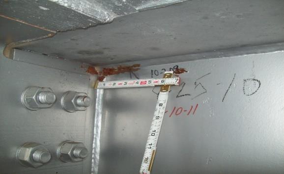
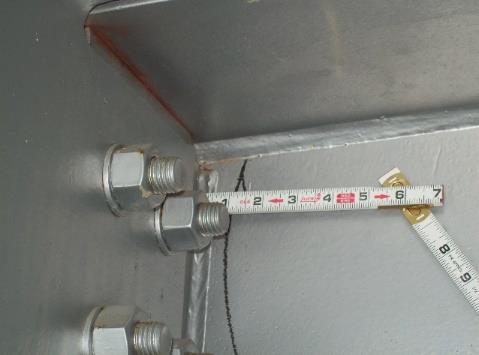
15 Cracks and Retrofits (1991) Girder web plate Fatigue crack Stop drill hole(s) Intersecting weld gap crack path arrest Gusset plate/web gap Crack in the Web Near Weld
 introduced by the K-brace members F v Horizontal force (F H ) of K-brace causing out-of-plan")
16 Cracks and Retrofits (1991) Initially cracks were classified as distortion-induced fatigue cracks Thought to be due to the horizontal force component (F H ) introduced by the K-brace members F v Horizontal force (F H ) of K-brace causing out-of-plan bending F H


17 Cracks and Retrofits (1991) Later the distortion-induced fatigue cracks were re-classified as constraint-induced fracture cracks at the close-proximity weld intersection Intersecting weld Intersecting weld


18 Retrofits (1994) Decrease restraint between the girder web connection to the K-brace and the lower lateral bracing Achieved by disconnecting the lower K-brace connection and the lower lateral bracing except at negative moment regions Loosely connected K- brace and lower horizontal bracing


19 Girder Floorbeam New Cycle of Fatigue Cracks (2009) New pattern of fatigue cracking at several locations in the EBL & WBL Cracks were found at the ends of the floorbeams: In the girder web to floorbeam connector plate weld In the upper floorbeam cope at the girder connector plate Fatigue cracks at Girder/Floorb eam connection Floorbeam Girder


20 Girder Floorbeam New Cycle of Fatigue Cracks (2009) Analysis performed by VTRC concluded that the cracks were caused by thermal differential between the concrete deck and the steel superstructure The floorbeams were non-composite while the girders were composite with the deck Differential thermal movement induced unresolved lateral loading at floorbeam ends resulting in formation of fatigue cracks Fatigue cracks at Girder/Floorbeam connection Floorbeam Girder

21 Analytical Approach and Fatigue Retrofit Recommendations
22 Outline Analytical Studies and Approach Purpose Findings Retrofit recommendations Retrofit Implementation Strategies Field Retrofit Implementations Retrofit at Fatigue-Prone Areas (connections) Health Monitoring System and Thermoelastic Stress Analysis (TSA) Bridge Current Status Conclusions
23 Analytical Studies and Fatigue Retrofit Recommendations Purpose Retrofit existing delta frame bridges to provide a long service life Study the ongoing fatigue cracking Conduct in-depth research studies (VTRC/VDOT) to determine the actual cause of cracking and to develop safe repair/retrofit methods Restore the structure to essentially infinite fatigue life
24 Analytical Studies and Fatigue Retrofit Recommendations Findings The bridges were structurally adequate and did not require replacement The fatigue and cracking problems were attributed to specific deficiencies in connection details The retrofit methods focused on the following areas: The deck to floorbeam composite behavior The fatigue-prone connection details between different elements of the bridge structure (K-brace, lateral bracing, etc.)
25 Analytical Studies and Fatigue Retrofit Recommendations Recommendations Establish two-way composite behavior between the concrete deck, the longitudinal girders and the transverse floorbeams through complete deck replacement (light weight concrete) Remove the horizontal lower lateral bracing members in the positive moment region, while reconnecting the loose bracing members in the negative moment region Improve the fatigue category details of the constraintinduced fracture connections Retrofit the floorbeam cope cuts to increase fatigue resistance and improve fatigue detail category

26 Retrofit Recommendations Establish two-way composite behavior between the deck, girders and the floorbeams Remove deck and install transverse shear studs along the top flange of the floorbeams for full composite action Section C-C

27 Retrofit Recommendations Remove the horizontal lower lateral bracing members in the positive moment region Re-connect horizontal lower lateral bracing in the negative moment region

 To improve fatigue performance")
28 Retrofit Recommendations Improve the fatigue category details of the constraint-induced fracture connections in both the positive and the negative moment regions Various fatigue-prone connection repair types (A, B, C, D, E, F) To improve fatigue performance category


29 Retrofit Recommendations Examples of Improved fatigue category details in positive moment region
30 Retrofit Recommendations Examples of improved fatigue crack performance in negative moment region
31 Tasks Retrofit Implementation Strategies A detailed 3-D computer model was developed to model the overall structural response during the prescribed stages of retrofit construction and to ensure the structures lateral stability VDOT Staunton District Bridge Section awarded contract to implement the retrofit/rehabilitation plans provided by WRA The bridge abutments were replaced by the Virginia Alternate Abutment configuration including bearing replacement A health monitoring system was installed during construction; the actual structural behavior was correlated with the results of the 3-D computer model

32 Three dimensional finite element model As-built structure Staged construction Time dependent analysis for creep and shrinkage effects 7,750 joints 2,633 beam elements 6,452 plate elements 3-D Computer Model LARSA-4D

33 3-D Computer Model LARSA-4D All primary structural elements were modeled: Delta girders Floorbeams Concrete deck Lateral bracings K-bracing Portal bracing Lower Lateral Bracing

34 Concrete Deck Demolition and Construction Sequence Different deck replacement scenarios were considered The scenario that resulted in the lowest stress conditions was chosen Maintained reasonable construction schedule

35 Replacement Deck Two-Way Bending Behavior Distribution of Positive Moments Distribution of Negative Moments
36 Field Retrofit Implementation Replaced concrete deck using light weight concrete in stages Installed shear studs on top of floorbeams to establish twoway composite action Implemented the recommended retrofit at both positive and negative moment regions Improved connection fatigue categories Replaced existing bearings at abutment Modified existing abutment to construct Virginia Alternate Abutment, eliminating joints


37 Field Retrofit Implementation Phase (2) Construction Sequence - Deck Removal (EBL)


38 Field Retrofit Implementation Phase (2) Construction Sequence - Deck Replacement (EBL)


39 Field Retrofit Implementation Looking along Floorbeam Showing New Studs Floorbeams Prior to Installation of Shear Studs


40 Retrofit at Fatigue-Prone Areas Repair Type A Positive moment region Before Removal of horizontal bracing and gusset plate Improved fatigue detail to Category (C) After


41 Retrofit at Fatigue-Prone Areas Repair Type D Positive moment region Before Reconnected loose vertical K-brace Welded bottom flange girder to connector plates After


42 Retrofit at Fatigue-Prone Areas Repair Type E Positive moment region Improved coping detail at floorbeam/gird er connection by grinding the cope smooth Drilled 2 - diameter hole to prevent crack propagation Before After


43 Retrofit at Fatigue-Prone Areas Repair Type B Negative moment region Increased stiffness of connectivity between floorbeams and girders Installed 5/16 weld on both sides of connector plates Before After


44 Retrofit at Fatigue-Prone Areas Repair Type F Retrofitted general diagonal crack floorbeam coping Before Terminated crack propagation at the tip with 2 - diameter drill Installed bolted splice plate to restore element strength capacity After

45 Retrofit at Fatigue-Prone Areas Before General existing fatigue cracks Before


46 Retrofit at Fatigue-Prone Areas Repair Type G Installed stop drill hole to terminate general existing fatigue cracks Applied along web/flange weld or within girders web Introduced to cracks and prevent future propagation After After
47 Structural Health Monitoring System Due to the sensitivity of the structures response to loadings and to ensure stability during construction, several instrumental systems were installed by VTRC. The monitoring systems included: Visual monitoring Thermoelastic Stress Analysis (TSA) monitoring Strain monitoring Movement detection monitoring

48 Visual Monitoring Provided streamline video monitoring of all construction activities Snapshots were taken every hour for specific construction activities Photos of the overall bridge site were taken every four hours


49 Thermoelastic Stress Analysis (TSA) Monitoring Measured small surface temperature changes associated with localized stresses at fatigue prone connections Temperature change is directly related to change in sum of the principal stresses under live load Documented high level stress at fatigue-prone connection due to instantaneous live load application (before retrofit)


50 Virginia Alternate Abutment Provides a Deck-Extension, Twin-Backwall Abutment Detail that delivers a truly jointless bridge solution Reference Civil Engineering Magazine June 2018 Issue the Virginia Difference for further Detail
51 2018 Bridge Structural Response and Retrofit Performance All retrofit recommendations have been implemented and completed for the EBL & WBL structures The concrete decks of the EBL and WBL structures have been replaced Both EBL and WBL structures are currently open to traffic The 3-D computer model predicted bridge behavior close to that reported by the health monitoring system The Thermoelastic Stress Analysis (TSA) system monitored the fatigue stresses developed in the retrofitted connection at the EBL structure and reported substantial reduction of developed stresses
52 2018 Bridge Structural Response and Retrofit Performance Both structures (EBL & WBL) are now subjected to a stringent inspection program by VDOT with increased frequency to ensure successful retrofit Inspection reports (2017 and 2018) confirmed the original fatigue cracks were confined; no additional cracks have formed The superstructure General Condition Rating (GCR) has been upgraded from level (4) to level (5) and will be increased to level (6) after 4 years of inspection with no additional cracking found Bridge structure load rating using LFR method showed significant capacity increase resulting from this structural retrofit
53 Conclusions All retrofit recommendations for the bridge structure rehabilitation to infinite fatigue life have been successfully implemented Recent bridge safety inspections confirmed adequate structural behavior with no indication of additional crack formations Thermoelastic Stress Analysis show significantly lower stresses at a retrofitted connection Retrofits and deck joint elimination have successfully extended the future service life of the structures while reducing future maintenance costs


54 Thank You - Questions Loai F. El-Gazairly, Ph.D., P.E. Associate Whitman, Requardt & Associates (WRA) Tel: E mail: lelgazairly@wrallp.com