Presentation to IMO as mentioned in the ST/SG/AC.10/C.3/2017/40 - (Russian Federation): Fibrereinforced plastics portable tanks
|
|
|
- Crystal Tucker
- 5 years ago
- Views:
Transcription
1 Committee of Experts on the Transport of Dangerous Goods and on the Globally Harmonized System of Classification and Labelling of Chemicals UN/SCETDG/52/INF.44 Sub-Committee of Experts on the Transport of Dangerous Goods 27 November 2017 Fifty-second session Geneva, 27 November-6 December 2017 Item 6 (c) of the provisional agenda Miscellaneous proposals for amendments to the Model Regulations on the Transport of Dangerous Goods: portable tanks Presentation to IMO as mentioned in the ST/SG/AC.10/C.3/2017/40 - (Russian Federation): Fibrereinforced plastics portable tanks Transmitted by the expert from the Russian Federation
2 Design, Manufacture and Testing of Tank Containers with Shells Made of Fiber Reinforced Plastic (FRP) Materials for Multimodal Transportation of Dangerous Goods Presented by: Professor, Doctor of Engineering Science Andrey E. Ushakov «Applied Advanced Technologies ApATeCh» (Russian Federation)
3 Container Transportation 1. According to ITCO information for 2016 year the world number of tank containers is more than pcs.; 90% are tank containers for chemical and petrochemical products; % of tank containers for multimodal transportation by all modes of transport (including maritime) is made of metal (steel, scarcely ever aluminum); 3. Rapid growth of dangerous goods transportation by 5-15% per year (including hydrochloric acid (UN No. 1789); phosphoric acid solution (UN No. 1805); sodium hydroxide solution (UN No. 1824)). 2
4 Current Operation Features 1. Aggressive substances transportation requires specific expensive protection of the inner surface of the metal shell body (rubber or special polymer coating); 2. Cleaning is a complex, time-consuming and labor-intensive process of tank steaming causing accelerated wear of the protective coatings; 3. Tank container service life is limited to that of the inner surface protection. 4. Low economic efficiency of operation and maintenance 3
5 FRP vs Steel 1. Global practice demonstrates higher efficiency of FRP products in areas which were considered to be conventional for application of metal structural materials (space engineering, aircraft industry, shipbuilding, bridge engineering, etc.); 2. Products manufactured from FRP materials require no additional surface protection from any aggressive substances. What is FRP Material? 1. Materials for FRP production are resins, fiber glass, carbon fiber, aramid fiber; 2. FRP product manufacturing process includes hand layup, vacuum infusion, filament winding, etc. 4
6 Advantages of FRP Materials 1. Physical and mechanical properties of FRP structures exceed similar properties of structures made of conventional structural metal materials: 2. Reduced energy consumption of FRP material product manufacture (no casting, forging or welding required); 3. Improved serviceability aspects; 4. Reduced final product (container) weight, allowing increased cargo weight; 5. Increased impact resistance (dampening); 6. No special processes are required for cleaning from remaining deleterious substances shipped Advantages of FRP shell 1. Reduced weight of structure; 2. Reduced transport expenses; 3. Reduced manufacture expenses; 4. High repairability; 5. Reduced maintenance costs connected with the structure repair 5
7 Scope The innovative materials, including wide range of FRPs are on the way in replacement of traditional materials. These challenges urge the rulemaking industry to make appropriate steps. For the moment IMO provides no requirements for materials, design, manufacture and testing of tank containers with FRP shell suitable for maritime transportation. 6
8 Our Achievements 1. Design 2. Simulation and calculations; 3. Materials; 4. Joints and connections; Materials: - Selection; - Testing; - Determination of design parameters 5. Design; 6. Testing of structural specimens and structural elements; 7. Technology and Production; 8. Tests; 9. Pilot operations. Tests: - Static tests; - Dynamic tests; - Hydraulic tests; - Ball drop test; - Fire resistance tests 7
9 Our Achievements 1. Design 8


10 1. Design 9
11 Our Achievements 2. Simulation and calculations 10


12 2. Simulation and calculations Multiscale Modeling of the Material State in the composite tank structure Micro- level modeling Meso-level modeling Structural level modeling Modeling of material structure Identification of the model Dynamic analysis and verification Effective material component properties: resin, fibers, fiber/resin interfaces Macro-mechanical model for viscous-elastic nonlinear material behavior taking into account dissipative properties and Material State Analysis of the Material State 11
13 2. Simulation and calculations Regulatory strength criteria applied to the composite tank For design loads: 1. Safety factor: К = S K 0 K 1 K 2 K S=1.5, K 0 =2, K 1 =1, K 2 =1.75 (static), K 2 =1.1 (dynamic) K 3 = Max tensile strain in any direction 0. 2%. 3. Buckling load factor 4.9 (pren 13121) 4. Additional criteria will be applied to guarantee strength of the structure during its service life (see next page) For testing loads: For inner pressure 0.6 MPa and minimum 4g horizontal inertia the tank must not have any damage and leakages. 12


14 2. Simulation and calculations Additional strength criteria applied to the composite tank 13


15 2. Simulation and calculations 14
16 Our Achievements 3. Materials selection List of goods allowed for transportation No. Name Hazard class UN No. 1 Phosphoric acid solution Hydrochloric acid (up to 37%) Sodium hydroxide solution

17 3. Materials selection 16
 Results of specimen exposure to: - hydrochloric acid (UN No. 1789); - phosphoric acid solution (UN No. 1805); - sodium hydroxide solution (UN No.")
18 3. Materials selection hydrochloric acid phosphoric acid sodium hydroxide 1 day (24 h.) 1 week (168 h.) 2 weeks (336 h.) 4 weeks (672 h.) 6 weeks (1000 h.) Results of specimen exposure to: - hydrochloric acid (UN No. 1789); - phosphoric acid solution (UN No. 1805); - sodium hydroxide solution (UN No. 1824) During 1000 hours at 50 С 17
19 Our Achievements 3. Materials Determination of design parameters 18

20 3. Materials Determination of design parameters 19
21 Our Achievements 4. Joints and connections 20


22 4. Joints and connections Finite-element model of the valve Strain distribution in the wound structural layers of the FRP shell under the design pressure 0.4 МPа 21
23 Our Achievements 5. Design 22


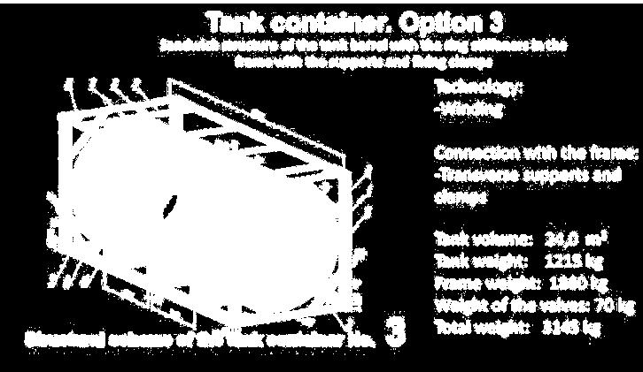
24 5. Design 1 Tank with FRP shell; 2 Small valve compartment; 3 Large valve compartment; 4 End frame; 5 Support ring; 6 Bottom longitudinal beam; 7 Middle longitudinal beam; 8 Longitudinal beam knee braces; 9 Bottom brace; 10 Front frame knee brace; 11 Lower support; 12 Top longitudinal beam; 13 Top-end transverse member. 1 Tank with FRP shell 2 Small valve compartment 3 Large valve compartment 4 Lower support 5 Manhole 6 Safety valve 7 Top loading-unloading unit 8 Air stop valve 9 Siphon pipe 23
25 Our Achievements 6. Testing of structural specimens and structural elements (measurement of creep and ageing factors according to the international standard EN978) 24

26 6. Testing of structural specimens and structural elements 25
27 6. Testing of structural specimens and structural elements Factor Structural specimen 1 Structural specimen 2 α 0,895 0,825 β 0,99 1,00 Value of the standard safety factor is K=S K0 K1 K2 K3=3.54 < Based on the requirements to the FRP tanks designed for multimodal transportation of aggressive chemicals, the minimal safety factor value shall be K=4 despite the fact that the actual experimental value is K = Nevertheless, even application of the safety factor K=4 will help to increase the level of allowable stresses by 5.775/4 100% = 144.3%. This, in turn, will help to reduce weight of the structural shell of the FRP tank by more than 30% 26
28 Our Achievements 7. Technology and Production 27

29 7. Technology and Production 28


30 7. Technology and Production Workshop tests with internal pressure 0,6 МPа 29
31 Our Achievements 8. Tests - Static tests; - Dynamic tests; - Hydraulic tests; - Ball drop test - Fire resistance tests; All tests complying with the current approaches used in the transport machine building for testing tank containers have been carried out under technical supervision of the Competent authority in the accredited laboratories. 30
32 Our Achievements 8. Tests - Static tests 31
33 8. Tests Static tests Test type Load Symbol Value 1 Lifting by top corner fittings 2R kg 2 Lifting by bottom corner 2R kg fittings 3 Stacking P 848 kn per corner post 4 Transverse racking P 150 kn 5 Longitudinal racking P 75 kn 6 Longitudinal restraint (static Combined 706 kn test) force of 2Rg 7 Walkways strength P 3 kn 8 Ladder strength P 2 kn 9 Longitudinal inertia test R kg 10 Lateral inertia test R kg 32

34 8. Tests Static tests 33
35 Load case Securing the container in the longitudinal direction 8. Tests Static tests Load combinations Vertical load on the tank 1g from the cargo weight Vertical load on the tank 1g from the tank weight External tensile and compression forces of kn applied to one corner fitting and kn applied to two corner fittings. Strength criteria of the tank K>5.775, e д 0.2% Conformity Conforms Strength analysis of the container under longitudinal securing ISO-1496 K>5.775, e д 0.2% Conforms Strength analysis of the container under transverse securing ISO-1496 K>5.775, e д 0.2% Conforms Strength of contact areas ISO-1496 K>5.775, e д 0.2% Conforms Load moving towards the tank and its fastenings ISO-1496 K>5.775, e д 0.2% Conforms Horizontal load applied towards the tank and its fastenings under 90 degrees Vertical bottom-to-top load to the tank and its fastenings Vertical top-to-bottom load to the tank and its fastenings ISO-1496 K>5.775, e д 0.2% Conforms ISO-1496 K>5.775, e д 0.2% Conforms ISO-1496 K>5.775, e д 0.2% Conforms 34
36 Our Achievements 8. Tests - Dynamic tests 35
37 8. Tests Dynamic tests Dynamic Test Scheme According to the Manual of Tests and Criteria, UN, Section 41, Part IV 36

38 8. Tests Dynamic tests 37

39 8. Tests Dynamic tests Speed of crash car, Max longitudinal acceleration, g km/h Fitting G Fitting F 5,2 3,1 2,9 7 4,4 5 9,1 8,3 6,8 10 9,2 10,3 13,5 9,7 10, ,4 11,8 Oscillogram of acceleration in the fitting G at the impact speed 14 km/h fitting G Oscillogram of acceleration in the fitting F at the impact speed 14 km/h fitting F 38
40 Our Achievements 8. Tests - Hydraulic tests 39


41 8. Tests Hydraulic tests Design pressure 0,4 МPа Test pressure 0,6 MPa After reaching the test pressure 0,6 МPa the tank container stayed under the load for 30 minutes. 40
42 Our Achievements 8. Tests - Fire resistance tests 41

43 8. Tests - Fire resistance tests 42
44 Summary March 2014: Start of development The tank container is designed for transportation of dangerous goods by road, rail and sea December 2015: Approval by the Competent authority for transportation by road and rail transport Tank container ADR code Technical data Parameter Value L4DN Dimension type Dimension code and container type 1СС 22К2 Max gross mass R, kg Total capacity of the tank barrel, m3 24±0,48 Design pressure, МPа 0,4 43
45 Our Achievements 9. Pilot operation 44
46 9. Pilot operation List of goods allowed for transportation No. Name Hazard class UN No. 1 Phosphoric acid solution Hydrochloric acid (up to 37%) Sodium hydroxide solution Parameters checked during inspection of the chemically resistant layer and fire resistant coating of the FRP shell 1. Inner Surface macrodefects; 2. Color in the inspection surfaces; (Shell surface area for measurements); 3. Appearance in the inspection surfaces; 4. Roughness in the inspection surfaces; 5. Thickness in the inspection points; 1.1 Cracking; 1.2 Delamination; 1.3 Pinholes; 1.4 Bubbles; 3.1 Luster; 3.2 Mud retention 3.3 Chalking; 45

47 9. Pilot operation 46

48 9. Pilot operation Operation route - 5 С Operation conditions: from - 42 С to +25 С Distance run: km - 42 С Total exposure time to hydrochloric acid of the chemically resistant layer:890 h. 47
49 Implementation 1. Transport equipment with shells made of FRP materials is already operated; 2. Such situation constrains use of tank containers with FRP shells in multimodal use (only for road and railway transport); 3. Considering the work performed it seems reasonable to establish similar requirements for use of transport equipment with FRP shells for maritime transport. 48
50 What is Next? 1. Development of the following standard requirements for all tank containers with FRP shells in partnership with all IMO member countries: - Design; - Manufacture; - Testing; - Certification. 2. Approval of tank containers with FRP shells for international maritime transportation. Who Benefits? 1. Safe transportation (technical and environmental aspects); 2. Consignee (receives higher quality end product); 3. Transport industry (transportation of larger cargo quantities in one freight transportation unit, extended service life of tank containers and increased handling frequency); 4. IMO (promotion of innovations improving maritime transportation efficiency and safety). 49
51 What is Next? Keeping in mind the information presented the Russian Federation has submitted to the IMO the Draft of the New Chapter for the IMDG Code on FRP matters (MSC98/20/11). All interested Parties are invited to support the paper and to take part in the development of requirements for tank containers with FRP shells. 50

52 Thank you! 51