The following attachment is for Public Inputs No. 3 19
|
|
|
- Martin Miles
- 5 years ago
- Views:
Transcription
1 The following attachment is for Public Inputs No. 3 19
2 NFPA Standard on Protective Ensembles for Structural Fire Fighting and Proximity Fire Fighting TIA Log No Reference: Various Comment Closing Date: February 13, 2013 Submitter: Steven Corrado, UL LLC and Pam Kavalesky, Intertek Testing Services 1. Revise to read as follows: ASTM F2412, Standard Test Method for Foot Protection, Revise to read as follows: The following information shall also be printed legibly on each product label with all letters at least 1.5 mm (1 16 in.) in height: (1) Manufacturer s name, identification, or designation (2) Manufacturer s address (3) Country of manufacture (4) Manufacturer s element identification number, lot number, or serial number (5) Month and year of manufacture, not coded (6) Model name, number, or design (7) Size or size range (8) Principal material(s) of construction include at least the identification of the fiber or material type used in the outer shell, moisture barrier, thermal liner, glove lining, gauntlet, and wristlet (9) Where the principal material of construction used in a garment is a component that is listed the component name under which it is listed shall be identified. (10) (9) Cleaning precautions For garments only, where the principal material of construction is a component that is listed, the component name under which it is listed shall be identified For garments only, where the thermal liner, moisture barrier, and outer shell are separable, each separable layer shall also have a label containing the information required in 5.1.7(4) through 5.1.7(9) * For footwear only, principal materials of construction shall include at least the outer shell, moisture barrier, and thermal liner materials. Generic names of materials shall be used. Additional materials that are used throughout the majority of the boot shall also be listed on the label * For helmets only, principal materials of construction shall include generic terminology for the shell material provided * For gloves only, principal materials of construction shall include at least outer shell, moisture barrier, thermal liner, and wristlet materials. Generic names of materials shall be used. The type of leather shall be listed, such as cow leather, elk leather, and so forth. Additional materials that are used throughout the majority of the glove body shall also be listed on the label. 3. Delete existing through Revise Paragraph to read as follows: The glove interface component composite, including, but not limited to, trim, external labels, and external tags, but excluding hardware and hook and pile fasteners that do not directly contact the wearer s body, shall be tested for resistance to flame as specified in Section 8.4, Flame Resistance Test 3, and shall not have an average char length of more than 100 mm (4 in.), shall not have an average afterflame of more than 2.0 seconds, shall not melt or drip, and shall not have the amount of consumed materials exceed 5 percent.
3 5. Revise Paragraph to read as follows: The glove extension composite, including, but not limited to, trim, external labels, and external tags, but excluding hardware and hook and pile fasteners that do not directly contact the wearer s body, shall be tested for resistance to flame as specified in Section 8.4, Flame Resistance Test 3, and shall not have an average char length of more than 100 mm (4 in.), shall not have an average afterflame of more than 2.0 seconds, shall not melt or drip, and shall not have the amount of consumed materials exceed 5 percent. 6. Revise to read as follows: Footwear soles and heels shall be tested for resistance to abrasion as specified in Section 8.23 Abrasion Resistance Test, and the relative volume loss shall not be greater than mm Revise to read as follows: Hoods shall be individually tested for resistance to shrinkage as specified in Section 8.24, Cleaning Shrinkage Resistance Test, and shall not have the measurements made from the top of the hood to the marks at the back and both sides of the hood exhibit shrinkage of more than 5 percent, and shall have the hood opening meet the requirements specified in Revise and add a new Table (c) to read as follows: The wash cycle procedure and water levels specified in Table (a), and Table (b) and Table (c) shall be followed. In addition, the G force shall not exceed 100 G throughout the wash cycle. Table (c) Water Level for Gloves and Glove Pouches Operation Wash Cycle Procedure Low Water Level High Water Level + 1 cm + 1 cm (3/8 in) (3/8 in) cm in cm in Gloves Glove Pouches Revise to read as follows: The percent shrinkage of each hood face opening dimension shall be individually calculated, recorded, and reported The percent shrinkage of each of the three dimensions from the top of the hood to the marks along the basic plane shall be individually calculated, recorded, and reported * The average percent shrinkage of all hood face opening dimensions for each all specimens shall be calculated, recorded, and reported * The average percent shrinkage of the three dimensions from the top of the hood to the marks along the basic plane for each all specimens shall be calculated, recorded, and reported Pass or fail performance shall be based separately on the average percent shrinkage of the hood face opening dimensions and the average percent shrinkage of the three dimensions from the top of the hood to the marks along the basic plane for each all specimens. One or more hood specimens failing this test shall constitute failing performance.
4 10. Replace existing through with the following: Each of the three dimensions from the top of the hood to the marks along the basic plane before and after laundering shall be recorded and reported The percent shrinkage of each hood face opening dimension shall be individually calculated, recorded, and reported The percent shrinkage of each of the three dimensions from the top of the hood to the marks along the basic plane shall be individually calculated, recorded, and reported * The average percent shrinkage of all hood face opening dimensions for all specimens shall be calculated, recorded, and reported * The average percent shrinkage of the three dimensions from the top of the hood to the marks along the basic plane for all specimens shall be calculated, recorded, and reported Pass or fail performance shall be based separately on the average percent shrinkage of the hood face opening dimensions and the average percent shrinkage of the three dimensions from the top of the hood to the marks along the basic plane for all specimens. 11. Revise Paragraph to read as follows: Samples for conditioning shall be in the form of a pouch as described in Revise Paragraph to read as follows: Samples for conditioning shall be in the form of a pouch as described in Revise (4)* and add a new (5) to read as follows: (4)* Calibration of the tiles shall be checked every 10 tests (50 test runs) or prior to each day of testing, whichever is the less frequent, to ensure that they are not being worn smooth or otherwise damaged. (5) If the five consecutive test results of the measurements (for each configuration) show a systematic increase or decrease of more than 10% of the initial reading, then one or more further test runs shall be carried out until a sequence of five are obtained that do not show a systematic increase or decrease of greater than 10%. 14. Revise and to read as follows: While standing, each test subject shall grasp the cylinder so that the wrist creates a straight line with the hand. The elbow is against the side of the body, creating a right angle, throughout the duration of the test and the arm bend creates a right angle Each test subject shall make five successive attempts to twist the cylinder in the appropriate direction exerting as much force as possible. The range of motion of the subject's arm wrist shall indicate the end of the twisting cycle. The average maximum force over the five attempts shall be the barehanded control value. 15. Renumber Annex items as follows: A in the Annex becomes A A in the Annex becomes A A in the Annex becomes A
5 16. Add new Annex items as follows: A This average should be based on a total of 12 values of percentage shrinkage with four values per specimen. A This average should be based on a total of 9 values of percentage shrinkage with three values per specimen. 17. Add new Annex Items to read as follows: A This average should be based on a total of 12 values of percentage shrinkage with four values per specimen. A This average should be based on a total of 9 values of percentage shrinkage with three values per specimen. Submitter s Substantiation: 1. The ASTM 2412 Standard needs to be updated to the current edition. 2, 3, and 14. The specific requirements for glove labels, which included type of fiber or material type, were inadvertently included in the generic list of requirements for labels on all ensemble elements. Since the majority of fabrics and materials used in construction of many of the ensemble elements contain multiple fibers and numerous blends, even attempting to include this level of detail on every product label would cause mass confusion. The issue becomes even more exacerbated by the minimum font sizes required on label text and by a garment specific label requirement, also included in the generic list, which mandates explicit component names as per the certification listing. This change provides the generic requirements for all labels, and then separates the specific ensemble element label requirements into subsets to avoid any interpretation issues. 4. The NFPA 1971 proposal ( , Log CP-50) neglected to include the test method reference to Section 8.4 as well as the requirement for char length. NFPA 1971, 2013 edition references several flame resistance tests. It is important the standard references the correct flame resistance test and section number to insure the correct testing procedures are being followed. It was also the technical committee s intent, based on historical data, to have the glove interface component evaluated for char length in addition to afterflame. 5. The NFPA 1971 proposal ( , Log CP-50) neglected to include the test method reference to Section 8.4 as well as the requirement for char length. NFPA 1971, 2013 edition references several flame resistance tests. It is important the standard references the correct flame resistance test and section number to insure the correct testing procedures are being followed. It was also the technical committee s intent, based on historical data, to have the glove extension component evaluated for char length in addition to afterflame. 6. This change brings this requirement in line with EN ISO 20345: The current laundering method described in Section only accounts for water levels when laundering garments and CBRN Materials. The 2013 edition of NFPA 1971 now requires gloves and glove pouches to be laundered using Section as a precondition. However a table for gloves and glove pouch water levels were not included. The water levels for the glove and glove pouch wash cycle needs to be specified in NFPA 1971, 2013 edition in order to allow for the front load wash machines to be properly programmed at the testing laboratories. The highest water levels currently in the standard were chosen to account for usage of both 35 lb and 50 lb capacity front-loading machines. The higher levels will also accommodate a full load of gloves/glove pouches and eliminate any risk associated with residual detergent. 8, 9, 15 and 16. Some changes made to the way the measurement of hood shrinkage were specified in cleaning shrinkage as part of the NFPA revision would prevent any hood from being certified to the new requirements. There was also an inconsistency between how hood shrinkage was evaluated for both thermal and cleaning shrinkage for the interpretation of test results that would lead to inconsistent determinations of compliance among testing laboratories. The proposed changes using the same approach established in the 2007 edition of NFPA 1971 for applying cleaning shrinkage criteria while clarifications have been made for interpretation of permitted shrinkage in both cleaning and thermal shrinkage test methods.
6 10. NFPA 1971, 2013 edition has sections for glove pouch construction, sections and Section , section for Liquid Penetration Resistance, should reference section for moisture barrier testing. 11. NFPA 1971, 2013 edition has sections for glove pouch construction, sections and Section , section for Viral Penetration Resistance, should reference section for moisture barrier testing. 12. The ISO standard does not provide criteria for the evaluation of systematic increase or decrease of values. Also, the current calibration language is not clear. 13. The test apparatus will be maxed out if the test subject uses their arm s range of motion to perform this test. In order to achieve more accurate results it is important the test subject use their wrist s range of motion to perform this test. Emergency Nature: This TIA seeks to correct errors and omissions that were overlooked during the Fall 2013 revision cycle process of NFPA Additionally, some parts of this TIA correct circumstances in which the standard could adversely impact a method or product that was inadvertently overlooked in the total revision process.
7 The following attachment is for Public Inputs No

8 NFPA Standard on Protective Ensembles for Structural Fire Fighting and Proximity Fire Fighting TIA Log No Reference: Various Comment Closing Date: June 14, 2013 Submitters: Steven Corrado, UL and Pam Kavalesky, Intertek 1. Revise to read as follows: Gloves shall be tested for grip as specified in Section 8.38, Grip Test, and shall not have a drop of force of more than 30 percent from the peak pull force value in any 0.2 second interval. 2. Revise Section 8.38 to read as follows: Samples for conditioning shall be whole gloves pairs Specimen glove pairs shall be tested after being wet conditioned for wet conditions as specified in Pulling Device. The pulling device shall be a 3.2 cm (1¼ in.) diameter fiberglass pole attached to an overhead calibrated force measuring device in such a fashion that pulls on the pole will be perpendicular to the ground and downward in direction. This pole shall be used until surface degradation occurs. The force measuring system shall provide a graphical plot of force-vs-time Test subjects shall be selected so that their hand dimensions are as close as possible to the middle of the range for hand length and hand circumference as specified in Table (ab) and Table (d) for size small and size large gloves. At least three test subjects shall be selected for both size small and size large The test subject and the test subject s hand shall be positioned as shown in Figure (a) and Figure (b), and as described below: shall then make three pulls on the pulling device with gloves with peak and minimum pull force values measured. Pulls shall be performed as described through The test subject shall extend the arms in front of the body at shoulder height to grab the pulling device for pulling vertically down from the ceiling. Figure (a) Position of test subject body, arms, and hands with respect to pole. Photo Courtesy Intertek Testing Services, Used by Permission.
9 Figure (b) Close-up of position of test subject hands on pole. Photo Courtesy Intertek Testing Services, Used by Permission The test subject shall stand facing the pole with feet shoulder width apart. with feet together, firmly planted on the ground, and knees slightly bent While wearing specimen gloves, the test subject shall grasp the pole with the bottom of the bottom hand at a height equal to the height of the subject. The stand shall be adjusted such that the cushioned bar is touching the test subject s chest. The stand shall prevent the test subject s forward movement during the pull The hands shall be stacked on each other and the thumbs shall not overlap the fingers. test subject shall stand in a comfortable pulling position with the arms bent at an angle of approximately 90 degrees and, in any case, the arms shall not be completely extended or touching the body The body shall be distanced from the pole so that the forearms are approaching vertical and in plane with the pole. test subject shall grasp the pulling device with hands next to each other. Thumbs shall not overlap the fingers The elbows shall be shoulder width apart, rotated neither fully in (arms parallel to the pole) nor fully out (arms perpendicular to the pole). test subject shall pull the rope or pole with as much pulling force as possible in a smooth, steady, swift, and non-jerking action. The test subject shall not bend the knees further or pull down with body weight during the pull The test subject shall continuously pull on the pulling device for a minimum of 5 seconds, +1/ 0 seconds. The test subject shall continue to pull until the test facilitator observes a peak pulling force and instructs the test subject to end the pull The test subject shall pull the pole with as much pulling force as possible in a smooth, steady, swift, and nonjerking action for 5 +1/-0 seconds. The test subject shall minimize forward or backward movement during the pull as much as possible. The test subject shall not bend the knees or pull down with body weight during the pull. The test subject shall continue to pull until the test facilitator instructs the test subject to end the pull at 5 +1/-0 seconds The test subject shall repeat the pull described above for a total of three pulls The peak pull force value for each individual pull shall be recorded and reported. Any drop in force of greater than 30% in any 0.2-second interval, as measured in the graphical plot of force-vs-time, shall be recorded and reported The minimum pull force value occurring after the peak pull force value shall be recorded and reported The percentage drop between the peak pull force value and the minimum pull force value shall be calculated, recorded, and reported The individual percentage drop between the peak pull force value and the minimum pull force value shall be used to determine pass or fail performance. Any drop in force of greater than 30% in any 0.2-second interval shall constitute failing performance.
10 Submitter s Substantiation: As currently written, more information is needed to fully explain how the pulls are to be performed, and also how the graphic results are to be interpreted. This is necessary to ensure consistent testing is performed. The test method as currently written does not provide sufficient detail in order for the test to be consistently applied in the evaluation of glove grip and requires interpretation of the testing laboratory to determine the appropriate body and hand position, which have a significant impact on the test results. Specific changes have been proposed in the position of the test subject s body and hands that alter the original instructions for performing the test. The additional details are intended to ensure that laboratories performing this test conduct the test in exactly the same way. Photographs of the proper positioning of the test subject body and hands with respect to the pole are included in the proposed modifications to provide a clear interpretation for running this part of the test. In addition, it is proposed to base the performance of glove grip on a change in the measured force relative to the time interval in which that change occurs. Consequently, the criteria in paragraph have been modified. This modification was necessary because the degree of test subject hand slipping on the pole can occur at varying rates (force over time) leading to widely different application of the test results and potential failure of gloves that are considered to have acceptable performance. These changes were developed as the result of a meeting between Intertek Testing Services, the North Carolina State University Textile Protection and Comfort Center, and Underwriters Laboratories, where these organizations worked together to determine how to consistently run the test method and achieve better precision in test results. The involvement of these organizations and their work on this test method were pursuant to a recommendation made by the Technical Committee on Structural and Proximity Fire Fighting Protective Clothing during a committee teleconference held December 2012 where specific problems with the test method and its application in NFPA 1971 were identified. Emergency Nature: The document contains an error or an omission that was overlooked during a regular revision process. After interlaboratory coordination it was determined that the additional language is necessary to perform consistent testing and to ensure a consistent level of compliant product available to users.
11 NFPA 1971-Proposed 2013 Edition Standard on Protective Ensembles for Structural Fire Fighting and Proximity Fire Fighting TIA Log No Reference: 2.3.2, 2.3.8, , and Comment Closing Date: June 18, 2012 Submitter: Jim Reidy, Texas State Association of Fire Fighters 1. Delete the reference in as follows: ASTM Publications. ASTM F 2700, Standard Test Method for Unsteady State Heat Transfer Evaluation of Flame Resistant Materials for Clothing with Continuous Heating, Add a reference in as follows: ISO Publications. ISO 17492, Clothing for Protection Against Heat and Flame Determination of Heat Transmission on Exposure to Both Flame and Radiant Heat, Revise the Section and as follows: Apparatus. The test apparatus specified in ASTM F2700, Standard Test Method for Unsteady State Heat Transfer Evaluation of Flame Resistant Materials for Clothing with Continuous Heating ISO 17492, Clothing for Protection Against Heat and Flame Determination of Heat Transmission on Exposure to Both Flame and Radiant Heat Procedure. Thermal protective performance testing shall be performed in accordance with ASTM F 2700, Standard Test Method for Unsteady State Heat Transfer Evaluation of Flame Resistant Materials for Clothing with Continuous Heating ISO 17492, Clothing for Protection Against Heat and Flame Determination of Heat Transmission on Exposure to Both Flame and Radiant Heat, shall be used with the following modifications: (1) An exposure heat flux of 84 kw/m 2, ±2 kw/m 2, (2.0 cal/cm 2 s, ±0.05 cal/cm 2 s) shall be used. (1 2) The contact configuration shall be used for testing of all material specimens. (2 3) The heat transfer performance value thermal threshold index analysis method shall be used with calculations made using the heat flux in calories per square centimeter per second shall be and reported as the TPP rating. Submitter s Substantiation: During the new business item of the NFPA 1851 ROC meeting in San Antonio on April 3 and 4, 2012 a situation with the new ASTM F2700 test method as it relates to NFPA 1971 was brought up. After much discussion of the available data and the differences in the data of both TPP test methods for the same composites, the Technical Committee agreed that there was a need to file a TIA for NFPA 1971 based on the significance of the data presented at the meeting and the potential to negatively affect the end users. It was not the intent of the Technical Committee to increase or decrease the TPP value as the Committee agreed during the process that a 35 TPP as a minimum would adequately protect the firefighter. Technical Merit: In the F2011 Report on Proposals for (Log #103), the Technical Committee on Structural and Proximity Fire Fighting Protective Ensembles provided an action for replacing the currently referenced ISO test method that measures thermal protective performance (TPP) with ASTM F2700. This change was believed to offer equivalent procedures and to provide additional details in conducting the test. Nevertheless, some of the specific details provided in the newer ASTM F2700 test method have been found to cause apparent significant differences in the currently reported TPP values for coat and pant garment material composites. Limited laboratory work using ASTM F2700 has neither resulted in the identification of any specific correlation that can be made for the amount of offset in TPP values that is resulting from the implementation of the new test method nor the determination of differences between the two test methods that can explain the variation of test results. Furthermore, it is unknown what effects the new test method will have on other types of composites being used in other elements, such as helmet ear covers, gloves, hoods, and wristlets.
12 Emergency Nature: The implementation of the new ASTM F2700 test method in place of the existing ISO test without reviewing the current performance criteria, has the potential of disqualifying a significant number of currently acceptable material composites that are used in the construction of structural firefighter protective clothing and will have unknown effects on the qualification of other structural firefighting protective elements such as gloves, hoods, and helmet ear covers. The protective garment material composites that are most likely to be affected by this change represent the many of the industry composites that have thermal protective performance (TPP) values in the range of 35 to 40 cal/cm 2 and the corresponding higher values of total heat loss levels that are positioned to lessen the stress effects for wearing protective clothing. The observed differences in TPP values were not the result of changes in the material technology and there was no intention of increasing the level of thermal protection and insulation provided by firefighter protective clothing. Therefore, the proposed TIA intends to correct a circumstance in which the revised document has resulted in an adverse impact on both products and the TPP method that was inadvertently overlooked in the total revision process.


13


14


15
16 Report on Comments November 2011 NFPA Log #86 FAE-SPF Jeffrey O. Stull, International Personnel Protection, Inc New text to read as follows: A system whereby a certification organization determines that a manufacturer has demonstrated the ability to produce a material, component, or product assembly that complies with the applicable requirements of this standard and establishes a follow-up program conducted by the certification organization as a check on the methods the manufacturer uses to determine continued compliance of listed materials, components, and product subassemblies with the applicable requirements of this standard. Certification organizations shall be permitted to provide component recognition for materials, components, and product subassemblies in accordance with the following requirements. Certification organizations shall only provide component recognition for those materials, components, and product subassemblies where specific design and performance criteria can be directly applied, where the specific criteria is not dependent on material, component, or product subassembly conformance to other criteria in this standard, and where the responsibility for the material, component, or product subassembly can be attributed to a single manufacturer. Only those materials, components, and product subassemblies that can be separately tested to specific requirements in this standard can be subjected to component recognition. For example, an outer shell material can be independently evaluated for flame resistance, heat resistance, thermal shrinkage resistance, tear strength, tensile strength, cleaning shrinkage, and water absorption resistance, and thus can be component recognized. Similarly, glove moisture barriers can be component recognized in some instances because even though the requirement specifies testing of the glove composite and seams, the conditioning used to qualify the moisture barrier specifies a particular material lay-up for testing both liquid penetration resistance and viral penetration resistance that is independent of the glove construction. It is also possible that the manufacturer of the glove moisture barrier is also responsible for the construction of the glove moisture barrier seams, when provided as an insert. In contrast, the toe reinforcement of footwear cannot be subjected to applicable testing without the mounting of the toe reinforcement in the footwear toe and thus cannot be component recognized. In the case of a garment composite, while it is possible to independently test a composite consisting of outer shell, moisture barrier, and thermal barrier for thermal protective performance and total heat loss testing, unless all three layers are provided by the same manufacturer, then component recognition cannot be applied. Certification organizations that provide component recognition shall meet all of the requirements specified in Section 4.2, Certification Program, and Section 4.3, Inspection and Testing. Certification organizations that provide component recognition shall require manufacturers of materials, components, and product subassemblies that are subject to component recognition to meet the applicable requirements specified in Section 4.4, Manufacturers Quality Assurance Program. Materials, components, and product subassemblies that meet the respective applicable requirements of this standard shall be listed. If requested by the manufacturer submitting for certification, the certification organization shall accept component recognition for those materials, components, or product subassemblies that have been component recognized by a different certification organization. This organization shall (1) meet the requirements of Section 4.2, Certification Program, (2) provide evidence of compliance for its conformity with the requirements for a certification organization, and (3) meet the applicable requirements of the product certification organization accepting the recognized components (see 4.3.Y). A certification organization shall have a process for developing requirements, which when fulfilled, will be the basis for utilization of certification of components from another certification organization meeting the requirements of this standard in the certification of the end product. When the requirements developed through the above process are fulfilled, the resultant utilization of certifications of components from another certification organization shall be comparable to either (1) the utilization of the certification organization s own certification of components; or if the certification organization does not certify components, (2) the certification organization s acceptance of results of evaluations from external sources. The original proposal was rejected because no agreement was reached at the Technical Correlating Printed on 4/30/2015 3
17 Report on Comments November 2011 NFPA 1971 Committee for the implementation of this proposal. However, the proposed language, which is slightly different than that which appeared in the original proposal has been adopted as part of another standard -- NFPA on flash fire protective clothing. The technical committee decided to hold this comment for further study. Affirmative: 28 4 Doan, S., Durby, T., Robison, R., Sisson, K. STULL, J.: This is an issue for the TCC to reconsider for NFPA 1971 and all documents in the project Log #114 FAE-SPF Jeffrey O. Stull, International Personnel Protection, Inc Revise text to read as follows: The measurements made in shall be repeated at horizontal and vertical extremes for the position the specimen(s) will occupy when set in the oven for heat resistance resting as shown by the grid illustrated in Figure The results of measurements at each corner of the cube shall be averaged with the center of the oven to establish an overall The Sensing Thermocouple Compensated Setting (STCS). ***Insert Figure here*** The proposed revisions are a step in the right direction for improving interlaboratory consistency for ensuring that test items are exposed to the specific temperature. Nevertheless, as different type of elements and components are subjected to oven heat resistance testing, a greater level of scrutiny is required to ensure that the temperature profile within the oven meets a certain tolerance. This is important for particularly large items such as footwear and helmets that within the oven meets a certain tolerance. This is important for particularly large items such as footwear and helmets that have a relatively high mass compared to smaller items such as flat material and hardware specimens. Some temperature mapping is needed to determine the ability of the oven to provide consistent temperature exposures of these items. The technical committee decided to hold this comment for further study. Affirmative: 28 4 Doan, S., Durby, T., Robison, R., Sisson, K. Printed on 4/30/2015 4
18 '! 10 meters l I ị, - I <4f meters - -,,,, \ L f1j :,, ' ' I -, _-\ r '!;, :1, ' : ':1, '\, I > ' - r _ l I : - I \ I 1 1. I \ I l I \/ I r : : 1,.' : I I,. / _. ' Ị I. ' I I I \ \ 1 t 'I - f I' t I \ I I I \,1 ( I.t "'\ 1 _ i ', '. I \, \ I II I.:.. Jl. ll I' t -.' I \.;, \ \ \ I \ f \ I \ I I ' '\I I i "' II I I I ' - I I I 1 - I - A. 1.I I I 3.3 meters ; I. J. t _/ \ '1,' I \ ' \. i l l I \ \'\. I/ &. : \ - - -:l' li ',-. ';. _, ' - r - _- /... '11.1. "".".'-.-,--r'....._, ' 'tj a'. - I d ' - t' I - ;.;. /.,... ' : I I I r I I '.-' I I.r l -- L Figure 8.X Course for Foot)\,-il:r,:A:gility. Cnurs. '... '.,; '
19
20 Report on Comments November 2011 NFPA 1971 Printed on 4/30/2015 5
21 Report on Comments November 2011 NFPA 1971 Printed on 4/30/2015 6
22 Report on Comments November 2011 NFPA 1971 Printed on 4/30/2015 3
23 Report on Comments November 2011 NFPA 1971 Printed on 4/30/2015 4
24 Report on Comments November 2011 NFPA 1971 Printed on 4/30/2015 5
25 Report on Comments November 2011 NFPA 1971 Printed on 4/30/2015 6
26 Report on Comments November 2011 NFPA 1971 Printed on 4/30/2015 7
27 Reference: Various TIA 13-2 (SC /TIA Log #1092) Tentative Interim Amendment NFPA 1971 Standard on Protective Ensembles for Structural Fire Fighting and Proximity Fire Fighting 2013 Edition Pursuant to Section 5 of the NFPA Regulations Governing the Development of NFPA Standards, the National Fire Protection Association has issued the following Tentative Interim Amendment to NFPA 1971, Standard on Protective Ensembles for Structural Fire Fighting and Proximity Fire Fighting, 2013 edition. The TIA was processed by the Technical Committee on Structural and Proximity Fire Fighting Protective Clothing and Equipment and the Correlating Committee on Fire and Emergency Services Protective Clothing and Equipment, and was issued by the Standards Council on March 7, 2013, with an effective date of March 27, A Tentative Interim Amendment is tentative because it has not been processed through the entire standards-making procedures. It is interim because it is effective only between editions of the standard. A TIA automatically becomes a public input of the proponent for the next edition of the standard; as such, it then is subject to all of the procedures of the standards-making process. 1. Revise to read as follows: ASTM F2412, Standard Test Method for Foot Protection, Revise to read as follows: The following information shall also be printed legibly on each product label with all letters at least 1.5 mm (1 16 in.) in height: (1) Manufacturer s name, identification, or designation (2) Manufacturer s address (3) Country of manufacture (4) Manufacturer s element identification number, lot number, or serial number (5) Month and year of manufacture, not coded (6) Model name, number, or design (7) Size or size range (8) Principal material(s) of construction (9) Cleaning precautions For garments only, where the principal material of construction is a component that is listed, the component name under which it is listed shall be identified For garments only, where the thermal liner, moisture barrier, and outer shell are separable, each separable layer shall also have a label containing the information required in 5.1.7(4) through 5.1.7(8) * For footwear only, principal materials of construction shall include at least the outer shell, moisture barrier, and thermal liner materials. Generic names of materials shall be used. Additional materials that are used throughout the majority of the boot shall also be listed on the label.
28 * For helmets only, principal materials of construction shall include generic terminology for the shell material provided * For gloves only, principal materials of construction shall include at least outer shell, moisture barrier, thermal liner, and wristlet materials. Generic names of materials shall be used. The type of leather shall be listed, such as cow leather, elk leather, and so forth. Additional materials that are used throughout the majority of the glove body shall also be listed on the label. 3. Delete existing through Revise Paragraph to read as follows: The glove interface component composite, including, but not limited to, trim, external labels, and external tags, but excluding hardware and hook and pile fasteners that do not directly contact the wearer s body, shall be tested for resistance to flame as specified in Section 8.4, Flame Resistance Test 3, and shall not have an average char length of more than 100 mm (4 in.), shall not have an average afterflame of more than 2.0 seconds, shall not melt or drip, and shall not have the amount of consumed materials exceed 5 percent. 5. Revise Paragraph to read as follows: The glove extension composite, including, but not limited to, trim, external labels, and external tags, but excluding hardware and hook and pile fasteners that do not directly contact the wearer s body, shall be tested for resistance to flame as specified in Section 8.4, Flame Resistance Test 3, and shall not have an average char length of more than 100 mm (4 in.), shall not have an average afterflame of more than 2.0 seconds, shall not melt or drip, and shall not have the amount of consumed materials exceed 5 percent. 6. Revise to read as follows: Footwear soles and heels shall be tested for resistance to abrasion as specified in Section 8.23 Abrasion Resistance Test, and the relative volume loss shall not be greater than 250 mm Revise to read as follows: Hoods shall be individually tested for resistance to shrinkage as specified in Section 8.24, Cleaning Shrinkage Resistance Test, and shall not exhibit shrinkage of more than 5 percent. 8. Revise and add a new Table (c) to read as follows: The wash cycle procedure and water levels specified in Table (a), Table (b) and Table (c) shall be followed. In addition, the G force shall not exceed 100 G throughout the wash cycle. Table (c) Water Level for Gloves and Glove Pouches Operation Wash Cycle Procedure Low Water Level High Water Level + 1 cm + 1 cm (3/8 in) (3/8 in) cm in cm in Gloves Glove Pouches Revise to read as follows:
29 The percent shrinkage of each hood face opening dimension shall be individually calculated, recorded, and reported The percent shrinkage of each of the three dimensions from the top of the hood to the marks along the basic plane shall be individually calculated, recorded, and reported * The average percent shrinkage of all hood face opening dimensions for all specimens shall be calculated, recorded, and reported * The average percent shrinkage of the three dimensions from the top of the hood to the marks along the basic plane for all specimens shall be calculated, recorded, and reported Pass or fail performance shall be based separately on the average percent shrinkage of the hood face opening dimensions and the average percent shrinkage of the three dimensions from the top of the hood to the marks along the basic plane for all specimens. 10. Replace existing through with the following: Each of the three dimensions from the top of the hood to the marks along the basic plane before and after laundering shall be recorded and reported The percent shrinkage of each hood face opening dimension shall be individually calculated, recorded, and reported The percent shrinkage of each of the three dimensions from the top of the hood to the marks along the basic plane shall be individually calculated, recorded, and reported * The average percent shrinkage of all hood face opening dimensions for all specimens shall be calculated, recorded, and reported * The average percent shrinkage of the three dimensions from the top of the hood to the marks along the basic plane for all specimens shall be calculated, recorded, and reported Pass or fail performance shall be based separately on the average percent shrinkage of the hood face opening dimensions and the average percent shrinkage of the three dimensions from the top of the hood to the marks along the basic plane for all specimens. 11. Revise Paragraph to read as follows: Samples for conditioning shall be in the form of a pouch as described in Revise Paragraph to read as follows: Samples for conditioning shall be in the form of a pouch as described in Revise (4)* and add a new (5) to read as follows: (4)* Calibration of the tiles shall be checked every 10 tests (50 test runs) or prior to each day of testing, whichever is the less frequent, to ensure that they are not being worn smooth or otherwise damaged. (5) If the five consecutive test results of the measurements (for each configuration) show a systematic increase or decrease of more than 10% of the initial reading, then one or more further test runs shall be carried out until a sequence of five are obtained that do not show a systematic increase or decrease of greater than 10%. 14. Revise and to read as follows:
30 While standing, each test subject shall grasp the cylinder so that the wrist creates a straight line with the hand. The elbow is against the side of the body, creating a right angle, throughout the duration of the test Each test subject shall make five successive attempts to twist the cylinder in the appropriate direction exerting as much force as possible. The range of motion of the subject's wrist shall indicate the end of the twisting cycle. The average maximum force over the five attempts shall be the barehanded control value. 15. Renumber Annex items as follows: A in the Annex becomes A A in the Annex becomes A A in the Annex becomes A Add new Annex items as follows: A This average should be based on a total of 12 values of percentage shrinkage with four values per specimen. A This average should be based on a total of 9 values of percentage shrinkage with three values per specimen. 17. Add new Annex Items to read as follows: A This average should be based on a total of 12 values of percentage shrinkage with four values per specimen. A This average should be based on a total of 9 values of percentage shrinkage with three values per specimen. Issue Date: March 7, 2013 Effective Date: March 27, 2013 (Note: For further information on NFPA Codes and Standards, please see Copyright 2013 All Rights Reserved NATIONAL FIRE PROTECTION ASSOCIATION
31 Reference: Various TIA 13-3 (SC /TIA Log #1100) Tentative Interim Amendment NFPA 1971 Standard on Protective Ensembles for Structural Fire Fighting and Proximity Fire Fighting 2013 Edition Pursuant to Section 5 of the NFPA Regulations Governing the Development of NFPA Standards, the National Fire Protection Association has issued the following Tentative Interim Amendment to NFPA 1971, Standard on Protective Ensembles for Structural Fire Fighting and Proximity Fire Fighting, 2013 edition. The TIA was processed by the Technical Committee on Structural and Proximity Fire Fighting Protective Clothing and Equipment and the Correlating Committee on Fire and Emergency Services Protective Clothing and Equipment, and was issued by the Standards Council on August 1, 2013, with an effective date of August 20, A Tentative Interim Amendment is tentative because it has not been processed through the entire standards-making procedures. It is interim because it is effective only between editions of the standard. A TIA automatically becomes a public input of the proponent for the next edition of the standard; as such, it then is subject to all of the procedures of the standards-making process. 1. Revise to read as follows: Gloves shall be tested for grip as specified in Section 8.38, Grip Test, and shall not have a drop of force of more than 30 percent from the peak pull force value in any 0.2 second interval. 2. Revise Section 8.38 to read as follows: Samples for conditioning shall be whole gloves pairs Specimen glove pairs shall be tested after being wet conditioned for wet conditions as specified in Pulling Device. The pulling device shall be a 3.2 cm (1¼ in.) diameter fiberglass pole attached to an overhead calibrated force measuring device in such a fashion that pulls on the pole will be perpendicular to the ground and downward in direction. This pole shall be used until surface degradation occurs. The force measuring system shall provide a graphical plot of force-vs-time Test subjects shall be selected so that their hand dimensions are as close as possible to the middle of the range for hand length and hand circumference as specified in Table (ab) and Table (d) for size small and size large gloves. At least three test subjects shall be selected for both size small and size large The test subject and the test subject s hand shall be positioned as shown in Figure (a) and Figure (b), and as described below: shall then make three pulls on the pulling device with gloves with peak and minimum pull force values measured. Pulls shall be performed as described through The test subject shall extend the arms in front of the body at shoulder height to grab the pulling device for pulling vertically down from the ceiling.

32 Figure (a) Position of test subject body, arms, and hands with respect to pole. Photo Courtesy Intertek Testing Services, Used by Permission. Figure (b) Close-up of position of test subject hands on pole. Photo Courtesy Intertek Testing Services, Used by Permission The test subject shall stand facing the pole with feet shoulder width apart. with feet together, firmly planted on the ground, and knees slightly bent While wearing specimen gloves, the test subject shall grasp the pole with the bottom of the bottom hand at a height equal to the height of the subject. The stand shall be adjusted such that the cushioned bar is touching the test subject s chest. The stand shall prevent the test subject s forward movement during the pull The hands shall be stacked on each other and the thumbs shall not overlap the fingers. test subject shall stand in a comfortable pulling position with the arms bent at an angle of approximately 90 degrees and, in any case, the arms shall not be completely extended or touching the body The body shall be distanced from the pole so that the forearms are approaching vertical and in plane with the pole. test subject shall grasp the pulling device with hands next to each other. Thumbs shall not overlap the fingers The elbows shall be shoulder width apart, rotated neither fully in (arms parallel to the pole) nor fully out (arms perpendicular to the pole). test subject shall pull the rope or pole with as much pulling force as possible in a smooth, steady, swift, and non-jerking action. The test subject shall not bend the knees further or pull down with body weight during the pull The test subject shall continuously pull on the pulling device for a minimum of 5 seconds, +1/ 0 seconds. The test subject shall continue to pull until the test facilitator observes a peak pulling force and instructs the test subject to end the pull The test subject shall pull the pole with as much pulling force as possible in a smooth, steady, swift, and nonjerking action for 5 +1/-0 seconds. The test subject shall minimize forward or backward movement during the pull as much as possible. The test subject shall not bend the knees or pull down with body weight during the pull. The test subject shall continue to pull until the test facilitator instructs the test subject to end the pull at 5 +1/-0 seconds The test subject shall repeat the pull described above for a total of three pulls.
33 The peak pull force value for each individual pull shall be recorded and reported. Any drop in force of greater than 30% in any 0.2-second interval, as measured in the graphical plot of force-vs-time, shall be recorded and reported The minimum pull force value occurring after the peak pull force value shall be recorded and reported The percentage drop between the peak pull force value and the minimum pull force value shall be calculated, recorded, and reported The individual percentage drop between the peak pull force value and the minimum pull force value shall be used to determine pass or fail performance. Any drop in force of greater than 30% in any 0.2-second interval shall constitute failing performance. Issue Date: August 1, 2013 Effective Date: August 20, 2013 (Note: For further information on NFPA Codes and Standards, please see Copyright 2013 All Rights Reserved NATIONAL FIRE PROTECTION ASSOCIATION
 (New), 8.27.4.2 and A.8.27.4.2 (New) TIA 13-4 (SC 14-10-6 / TIA Log #1159) Pursuant to Section 5 of the NFPA Regulations Governing the Development of NFPA Standards, the National Fire Protection")
34 Tentative Interim Amendment NFPA 1971 Standard on Protective Ensembles for Structural Fire Fighting and Proximity Fire Fighting 2013 Edition Reference: 5.4.4(8) (New), and A (New) TIA 13-4 (SC / TIA Log #1159) Pursuant to Section 5 of the NFPA Regulations Governing the Development of NFPA Standards, the National Fire Protection Association has issued the following Tentative Interim Amendment to NFPA 1971, Standard on Protective Ensembles for Structural Fire Fighting and Proximity Fire Fighting, 2013 edition. The TIA was processed by the Technical Committee on Structural and Proximity Fire Fighting Protective Clothing and Equipment and the Correlating Committee on Fire and Emergency Services Protective Clothing and Equipment, and was issued by the Standards Council on October 28, 2014, with an effective date of November 17, A Tentative Interim Amendment is tentative because it has not been processed through the entire standards-making procedures. It is interim because it is effective only between editions of the standard. A TIA automatically becomes a public input of the proponent for the next edition of the standard; as such, it then is subject to all of the procedures of the standards-making process. 1. Add a new 5.4.4(8) to read as follows: (8) A statement that the moisture barrier has not been evaluated for all chemicals that can be encountered during fire-fighting operations and information that the effects of chemical exposure on the moisture barrier are to be evaluated per the inspection procedures in NFPA Revise and add a new Annex A to read as follows: Each of the following liquids shall be tested separately against each test specimen: (1) Aqueous film-forming foam (AFFF), 3 percent concentrate (2) Battery acid (37 percent by weight sulfuric acid to water) (3)* Fire-resistant hydraulic fluid, phosphate ester base that does not contain aliphatic phosphates (4) Surrogate gasoline fuel C as defined in ASTM D471, Standard Test Method for Rubber Property Effect of Liquids, a 50/50 percent by volume of toluene and iso-octane (5) Swimming pool chlorinating chemical containing at least 65 percent-free chlorine (saturated solution). A (3) The types of liquids, specifically the hydraulic fluid liquid, were liquids that were identified as being in use or that could be encountered by the fire service in the early 2000 s. These liquids may not represent current day fire service use. While fire-resistant hydraulic fluid is still in use today, the industry has been transitioning to hydraulic fluids based on mineral oils. Research has shown that the identification of fire-resistant hydraulic fluid, phosphate ester base that does not contain aliphatic phosphate is a better representation of this type of fluid for conducting the liquid penetration resistance test. Issue Date: October 28, 2014 Effective Date: November 17, 2014 (Note: For further information on NFPA Codes and Standards, please see Copyright 2014 All Rights Reserved NATIONAL FIRE PROTECTION ASSOCIATION
35 The following attachment is for Public Inputs No
36 June 3, 2015 Debbie Baio National Fire Protection Association Public Fire Protection Division 1 Batterymarch Park., Quincy, Ma Office dbaio@nfpa.org Many blessings to you for your assistance in my completing the NFPA 1971 Public Input on a stretchable firefighter chinstrap. The main objective is for firefighter chinstraps to stretch partially absorbing or dissapating impact forces to helmets, especially the brims. As we discussed, the following may be inserted into the Public Input at your discretion. Sheet #1 Sheet #2 Sheet #3 Sheet #4 Sheet #5 Sheet #6&7 Language Revisions Intro comments Drawing Specifications Firefighters familiar with the chinstrap Reference of similar firefighter injuries. Please don t hesitate to contact me should you need additional information. Regards, Joe Lastik, joelastik@hotmail.com Cell: Brownfield Drive Greensburg, PA 15601
37 NFPA 1971 Specific Language Revisions Helmets shall be tested for retention ability as specified in Section 8.34, Retention System Test, without any break occurring and without any resulting slip or stretch of more than 20 mm (13 16 in.) no less than 1.5 inches (38.1 mm) nor more than 2 inches (50.8 mm) Helmets shall be tested for shell retention ability as specified in Section 8.43, Shell Retention Test, and shall not have the helmet shell separate from the helmet suspension and retention systems All materials utilized in the construction of helmet chin straps, excluding elastic and hook and pile fasteners where these items are placed so that they will not directly contact the wearer's body or hood or such material is covered with or within fire resistant material, shall be individually tested for resistance to flame as specified in Section 8.2, Flame Resistance Test 1, and shall not have a char length greater than 100 mm (4 in.), shall not show any visible afterflame 2.0 seconds after removal from the test flame, and shall not melt or drip All materials utilized in the construction of helmet chin straps, excluding elastic and hook and pile fasteners where these items are placed so that they will not directly contact the wearer's body or hood or such material is covered with or within fire resistant material, shall be individually tested for resistance to heat as specified in Section 8.6, Heat and Thermal Shrinkage Resistance Test, and shall not shrink more than 10 percent in any direction, and shall not melt, separate, or ignite. Helmet chin strap material shall meet the thermal shrinkage requirement for the length dimension only.
38 Need for a Stretchable Chinstrap Eric Lepore is a Western Pennsylvania volunteer firefighter who was injured in a house fire when debris fell on the rear brim of his N5A New Yorker MSA helmet violently pivoting his head backward causing neck and shoulder injuries. Eric suffered two dislocated shoulders, neck and shoulder trauma, was pulled from under fallen debris by fellow firefighters, and was off work for 7 weeks receiving extensive medical treatment. Because of of the 1971 NFPA regulation, a chinstrap tightly secures the helmet to a firefighter s head whereby impact forces on the helmet brim may be transferred to neck and shoulder muscles. To reduce the possibility of this type of injury, the proposed changes in 7.4.7, and of 1971 NFPA regulations would provide that an elastic strip would move within a fire resistant cover or sleeve to partially dissipate and absorb impact forces on helmets. Eric is not alone. Approximately 26% of firefighter injuries are head and shoulder related that may be partially addressed with a stretchable chinstrap. Testing was problematic because labs were limited to the elongation limits of the NFPA 1971 regulations and couldn t evaluate the physiological challenges of bodily injuries to a helmet off center ball drop test. Regardless of this request, a review of the ball drop test may be in order to evaluate off center impact forces on a helmet brim and other areas of the helmet to simulate actual fire conditions. The referenced chinstrap is conceptual at this point in development with suggestions and improvements to the design and materials welcomed by the NFPA Committee membership. Considering all the improvements in safety for firefighters especially after September 11, 2001, a review of the 43 year old 1971 regulation may be in order to permit elongation of firefighter chinstraps.
39 Lepore Chinstrap Spec Sheet No. Item Dimensions Materials 01 Spring Hooks 1.5 inches Stainless steel brass nomex 02 Quick Release Buckle 2.5 inches Nomex - fire resistant 03 Fire resistant 11.5 x 1 Nomex or nylon, polymer fire resistant non-elastic 04 Tubular Webbing 2.5 inches Polyester (15%) and cotton (85%) fire resistant 05 Non-fire resistant 2 x 1 cotton or Polyester with rubber or elastic strands elastic material
40 SPECIFICATIONS The following is taken in part from the Patent Application The chinstrap of approximately 19 inches long by 1 inch wide includes a strap body extending between the coupling members formed by spring hooks, quick release buckle, with the nonelastic portion being a fire resistant member woven construct of about 1 in width (Width Tolerance: +/- 1/16") and thickness of about forming a fire resistant member (NOMEX fibers or polyester (15%) and cotton (85% fire resistant blend). The elastic portion using textured polyester or cotton yarn coupled with neoprene rubber or elastic strands exhibits an elongation measurement of 115% (+/- 15%) such as manufactured by HNW, The Elastic People, of Pawtucket, Rhode Island. Woven elastic fabrics are dense with interlocking threads for a strong, premium product that will not narrow when stretched. The chinstrap further includes a fire resistant slip member surrounding the elastic portion of the strap that allows and protects the elastic portion to freely elongate or contract within the slip member. The slip member is preferably a tubular woven webbing member formed of synthetic fibers such as nylon, polypropylene or polyester and is intended to be the only member in contact with the skin of the user.
41 Firefighter Impressions The following Greensburg, PA area fire chiefs / firefighters are familiar with the Lepore Chinstrap: Location Chief/firefighter Phone Number Greensburg, PA Ed Hutchinson Mt. Pleasant, PA Jerry Lucia Carbon, PA Josh Caccia Fort Allen, PA Neil Kush Mid-Way, PA Rich Kepple Youngwood, PA Barry Karelitz Pennsylvania Fire Commissioner Tim Solobay,, is familiar with the Lepore Chinstrap. tsolobay@pa.gov ; ofce; bus cell; personal cell; PA Interstate Dr, Harrisburg, PA USA
42 Firefighters with Head and Neck injuries from falling debris Eric is not alone. Shoulder and neck injuries are not isolated incidents. The Fire-Related Firefighter Injuries Reported to NFIRS (National Fire Incident Reporting System), Volume 11, Issue 7 / February 2011, states that The head and shoulder regions account for an additional 26 percent of injuries. Examples Fort Worth, TX (July 04, 2014) - Two firefighters were treated for head and neck injuries when part of a ceiling and roof collapsed. Freeport, NY (January 8, 2014) - Firefighter injured after ceiling collapse and sustained neck and back injuries Detroit, MI A collapse caused neck and head injuries to two firefighters. Detroit, MI (May 30, 2013) Two firefighters suffered neck and back injuries, one suffered a severe concussion Tinton Falls, NJ (July 7, 2013) A firefighter suffered minor head and neck injuries.. nts.displaced.after.tinton.falls.blaze.aspx Holland, MI (January 16, 2013) Two firefighters are hospitalized with neck and back injuries after a portion of a roof collapsed on them.
43 Warrenton, OR (May 14, 2012) A Warrenton firefighter is recovering from neck and back injuries after a chunk of ceiling collapsed on him. Warren, MI (December 4, 2011) A firefighter was injured when something fell on him, and he suffered neck and shoulder injuries.. Jersey City, NJ (August 19, 2010) Steven Rosone suffered head, neck and shoulder injuries, Alberto Henriquez sustained a neck injury and Raymond Spellmeyer had a shoulder injury.. how_faces=true%26width=450%26action=like%26colorscheme=light%26height=80%22 Springfield, MA (August 28, 2008) Two firefighters suffered head and neck injuries when a kitchen ceiling collapsed on them.. Naples, FL (December 21, 2004) Two firefighters suffered neck, back and shoulder injuries when a part of a ceiling collapsed.. Statesboro, GA (June 27, 2014) One firefighter was taken to the hospital after getting hurt when the roof collapsed
44 Finger Lengths Inches Low High Average N W XW Low High Average Hand Circumference Hand breadth Inches N N W W XW XW N N N W W XW XW N N N W W XW XW Average Low High Low High Low High Low High Average Low High Average Low High Average Low High Average Low High Average Low High Average
45 Finger Lengths Low High Average N W XW Hand breadth N N W W XW XW Average Low High Low High Low High Hand Breadth Index Finger Length 64N Low 64N Hi 64W Low 64W Hi 64XW Low 64XW Hi 70N Low 70N Hi 70W Low 64N Low N Hi W Low W Hi XW Low XW Hi N Low N Hi W Low W Hi XW Low XW Hi N Low N Hi 90.93
46 76W Low W Hi XW Low XW Hi N Low N Hi W Low W Hi XW Low XW Hi N 82W 82XW 76N 76W 76XW 70N 70W 70XW 64N 64W 64XW
47 Hand Circumference N N W W XW XW Low High Low High Low High W Hi 70XW Low 70XW Hi 76N Low 76N Hi 76W Low 76W Hi 76XW Low 76XW Hi 82N Low 82N Hi 82W Low 82W Hi
48
49 82XW Low 82XW Hi
50
51 82N 82W 82XW 76N 76W 76XW 70N 70W 70XW 64N 64W 64XW
52
53 Report on Comments November 2011 NFPA 1971 Printed on 4/30/2015 4
54 Report on Comments November 2011 NFPA Log #86 FAE-SPF Jeffrey O. Stull, International Personnel Protection, Inc New text to read as follows: A system whereby a certification organization determines that a manufacturer has demonstrated the ability to produce a material, component, or product assembly that complies with the applicable requirements of this standard and establishes a follow-up program conducted by the certification organization as a check on the methods the manufacturer uses to determine continued compliance of listed materials, components, and product subassemblies with the applicable requirements of this standard. Certification organizations shall be permitted to provide component recognition for materials, components, and product subassemblies in accordance with the following requirements. Certification organizations shall only provide component recognition for those materials, components, and product subassemblies where specific design and performance criteria can be directly applied, where the specific criteria is not dependent on material, component, or product subassembly conformance to other criteria in this standard, and where the responsibility for the material, component, or product subassembly can be attributed to a single manufacturer. Only those materials, components, and product subassemblies that can be separately tested to specific requirements in this standard can be subjected to component recognition. For example, an outer shell material can be independently evaluated for flame resistance, heat resistance, thermal shrinkage resistance, tear strength, tensile strength, cleaning shrinkage, and water absorption resistance, and thus can be component recognized. Similarly, glove moisture barriers can be component recognized in some instances because even though the requirement specifies testing of the glove composite and seams, the conditioning used to qualify the moisture barrier specifies a particular material lay-up for testing both liquid penetration resistance and viral penetration resistance that is independent of the glove construction. It is also possible that the manufacturer of the glove moisture barrier is also responsible for the construction of the glove moisture barrier seams, when provided as an insert. In contrast, the toe reinforcement of footwear cannot be subjected to applicable testing without the mounting of the toe reinforcement in the footwear toe and thus cannot be component recognized. In the case of a garment composite, while it is possible to independently test a composite consisting of outer shell, moisture barrier, and thermal barrier for thermal protective performance and total heat loss testing, unless all three layers are provided by the same manufacturer, then component recognition cannot be applied. Certification organizations that provide component recognition shall meet all of the requirements specified in Section 4.2, Certification Program, and Section 4.3, Inspection and Testing. Certification organizations that provide component recognition shall require manufacturers of materials, components, and product subassemblies that are subject to component recognition to meet the applicable requirements specified in Section 4.4, Manufacturers Quality Assurance Program. Materials, components, and product subassemblies that meet the respective applicable requirements of this standard shall be listed. If requested by the manufacturer submitting for certification, the certification organization shall accept component recognition for those materials, components, or product subassemblies that have been component recognized by a different certification organization. This organization shall (1) meet the requirements of Section 4.2, Certification Program, (2) provide evidence of compliance for its conformity with the requirements for a certification organization, and (3) meet the applicable requirements of the product certification organization accepting the recognized components (see 4.3.Y). A certification organization shall have a process for developing requirements, which when fulfilled, will be the basis for utilization of certification of components from another certification organization meeting the requirements of this standard in the certification of the end product. When the requirements developed through the above process are fulfilled, the resultant utilization of certifications of components from another certification organization shall be comparable to either (1) the utilization of the certification organization s own certification of components; or if the certification organization does not certify components, (2) the certification organization s acceptance of results of evaluations from external sources. The original proposal was rejected because no agreement was reached at the Technical Correlating Printed on 4/30/2015 3
55 Report on Comments November 2011 NFPA 1971 Committee for the implementation of this proposal. However, the proposed language, which is slightly different than that which appeared in the original proposal has been adopted as part of another standard -- NFPA on flash fire protective clothing. The technical committee decided to hold this comment for further study. Affirmative: 28 4 Doan, S., Durby, T., Robison, R., Sisson, K. STULL, J.: This is an issue for the TCC to reconsider for NFPA 1971 and all documents in the project Log #114 FAE-SPF Jeffrey O. Stull, International Personnel Protection, Inc Revise text to read as follows: The measurements made in shall be repeated at horizontal and vertical extremes for the position the specimen(s) will occupy when set in the oven for heat resistance resting as shown by the grid illustrated in Figure The results of measurements at each corner of the cube shall be averaged with the center of the oven to establish an overall The Sensing Thermocouple Compensated Setting (STCS). ***Insert Figure here*** The proposed revisions are a step in the right direction for improving interlaboratory consistency for ensuring that test items are exposed to the specific temperature. Nevertheless, as different type of elements and components are subjected to oven heat resistance testing, a greater level of scrutiny is required to ensure that the temperature profile within the oven meets a certain tolerance. This is important for particularly large items such as footwear and helmets that within the oven meets a certain tolerance. This is important for particularly large items such as footwear and helmets that have a relatively high mass compared to smaller items such as flat material and hardware specimens. Some temperature mapping is needed to determine the ability of the oven to provide consistent temperature exposures of these items. The technical committee decided to hold this comment for further study. Affirmative: 28 4 Doan, S., Durby, T., Robison, R., Sisson, K. Printed on 4/30/2015 4
56 Report on Comments November 2011 NFPA Log #115 FAE-SPF Jeffrey O. Stull, International Personnel Protection, Inc New text to read as follows: Footwear shall be tested for agility performance as specified in 8.X and shall have an average percentage change in agility course time of no greater than 10 percent. This test shall apply to footwear. Samples for conditioning shall be whole footwear pairs. Footwear pair samples shall be preconditioned as specified in A minimum of five footwear pairs shall be used for specimens, each with a different test subject wearing each pair of footwear. Each pair of footwear shall be tested as a complete set of footwear in new, as distributed, condition. Footwear pair specimens shall not receive special softening treatments prior to tests. The test apparatus shall consist of an agility course laid out on a smooth, completely flat, wooden floor surface with cones positioned as shown in Figure 8.X ***Insert 1971_L115_Fig 8.X.4.1.1_F2011_R here*** Tape shall be used to mark the position of each cone and the starting and finishing line of the agility course. Eight 30 cm (12 in.) high traffic cones shall be used for marking the course as shown in 8.X Test subjects shall be selected so that they are able to complete the agility course wearing athletic running shoes in an average time of 20 seconds or less with a variation of no more than 10% as measured over three consecutive trials at 6 to 7 minute intervals after the test subjects has become accustomed to the course. Each test subject shall wear their own athletic running or cross training shoes for all baseline tests. The test subject shoes shall be in good condition and shall fit the test subject correctly. Each test subject shall be fitted with the correct size of test footwear involving a fitting process where a range of sizes for test footwear are made available to the test subject to allow their choice of the best fitting size. Each test subject shall wear a pair of running shorts and T-shirt while running the agility course. Normal athletic socks shall be worn when wearing either the athletic running shoes or the test footwear. No individual test subject shall run more than 15 tests in a day. The test operator for the test shall serve as the starter and timer for all tests conducted within a series of baseline and test footwear evaluations. A stopwatch with an accuracy of ±0.05 second shall be used to measure the agility course time for each test subject. The test operator shall use the starting commands, on your mark, get set, go establishing the same cadence of stating the commands for each test, starting the stop watch upon saying go. The test operator shall stop the watch when the test subject s leading foot crosses the finish line. Each test subject shall become familiar with the agility course by first walking the agility course three times and then running the agility course three times while wearing their own athletic running shoes. An interval of at least 6 to 7 minutes shall be used between successive runs of the agility course. Each test subject shall run the agility course three times while wearing their own athletic running shoes to establish baseline times for running the agility course as measured using a stopwatch. An interval of at least 6 to 7 minutes shall be used between successive runs of the agility course. Printed on 4/30/2015 5
57 Report on Comments November 2011 NFPA 1971 Each test subject shall remove their athletic footwear, don the test footwear, and walk the agility course three times while wearing the test footwear before conducting any timed tests; if any subject has a complaint about the specific footwear, the test subject shall be refit with a different pair of footwear as specified in 8.X.4.6. This step shall be concluded within 15 minutes after finishing the third baseline test specified in 8.X.5.2. Each test subject shall run the agility course a total of three times while wearing the test footwear to establish test times for running the agility course as measured using the stopwatch. An interval of at 6 to 7 minutes shall be used between successive runs of the agility course. Each test subject shall then remove the test footwear, put on their athletic running shoes, and shall run the agility course three additional times while wearing their own athletic running shoes to establish a second set of baseline times for running the agility course as measured using the stopwatch. An interval of at 6 to 7 minutes shall be used between successive runs of the agility course. If during any baseline or test footwear run a test subject slips, falls, develops a cramp, injuries him or herself, or incorrectly runs the course, then the test shall be halted and an additional run added subject using the same time intervals between runs. The average baseline run time shall be calculated for each test subject from the three initial and three follow-on baseline runs, using a total of six times. The average test footwear run time shall be calculated for each test subject from the three runs involving the wearing of the test footwear. The percentage change in agility course time shall be calculated using the following formula: % Change in Agility Course Time = Time (footwear) - Time (baseline) /Time (baseline) 100 The average percentage change in agility course time shall be calculated and reported for each test subject. The average percentage change in agility course time for all test subjects shall be calculated and reported for all test subjects. The average percentage change in agility course time for all test subjects shall be used to determine pass or fail performance. A gym floor, such as a basketball court, provides a uniform surface meeting these requirements. A timing gate or other accurate timing device may be used in lieu of a stopwatch if the timing device has an accuracy of ±0.05 second. Unlike other tests which have been accepted by the committee without any study for their validation, the presentation of test data, an evaluation of the test precision, assessments for correlation with field observations, or the basis for a suggested criteria, the proposed footwear agility test attempts to discriminate characteristics of footwear that affect firefighter agility. Currently, there are no criteria that address the ergonomic features of footwear as is the case for gloves, which are the subject of extensive functionality tests. The proposed criteria and test method attempt to have footwear manufacturers focus on changes that will improve the fits and function of firefighters. While the specific test procedures do not emulate fireground activity, the test succeeds by providing discrimination of footwear consistent with field observations as borne out in the correlation work. A copy of the study report for this work, which was made available to the task group in April 2010, is available for review at NFPA Headquarters. Note: Supporting material is available for review at NFPA Headquarters. The technical committee decided to hold this comment for further study. Affirmative: 28 4 Doan, S., Durby, T., Robison, R., Sisson, K. Printed on 4/30/2015 6
58 Report on Comments November 2011 NFPA Log #136 FAE-SPF Patricia A. Freeman, Globe Manufacturing Company, LLC Revise text to read as follows: Garment outer shells, or garment composite consisting of but not limited to outershell, thermal lining, and moisture barrier, shall be tested for radiant reflective capability as specified in Section 8.52, Radiant Protective Performance Test and shall have a thermal transfer threshold time of not less than 20 seconds. Many segments of the proximity fire fighting community have expressed extreme dissatisfaction with the life of the aluminized outer shell. By adding this sentence, we would allow for other possible materials and/or combinations to be used in proximity fire fighting, providing the performance requirements are met. The technical committee decided to hold this comment for further study. Affirmative: 28 4 Doan, S., Durby, T., Robison, R., Sisson, K Log #CC29 FAE-SPF Technical Committee on Structural and Proximity Fire Fighting Protective Clothing and Equipment, Revise text as follows: Garment outer shells, or garment composite consisting of but not limited to outershell, thermal lining, and moisture barrier, shall be tested for radiant reflective capability as specified in Section 8.52, Radiant Protective Performance Test and shall have a thermal transfer threshold time of not less than 20 seconds. Many segments of the proximity fire fighting community have expressed extreme dissatisfaction with the life of the aluminized outer shell. By adding this sentence, we would allow for other possible materials and/or combinations to be used in proximity fire fighting, providing the performance requirements are met. The technical committee decided to hold this comment for further study. Printed on 4/30/2015 7
59 HYDAULIC FLUIDS OVERVIEW First responders may encounter hydraulic fluid in many situations. Hydraulic fluid is used in a variety of industrial and noncommercial applications such as brakes, power steering systems and transmissions. Construction equipment requiring hydraulic fluid includes excavators, backhoes, bulldozers, and tractors. Other commercial vehicles such as garbage trucks also use hydraulic fluid. Additional applications requiring use of hydraulic fluids are found in aircraft flight control systems, lifts, and other industrial control systems. Hydraulic fluids of both current and outdated formulations may be encountered at waste disposal sites. Hydraulic fluids fall into three major groups: mineral oils, organophosphate esters, and polyalphaolefins. Water-in-oil formulations may contain up to forty percent water. Besides oils, esters, and polyalphaolefins, hydraulic fluid formulations may comprise many other chemical compounds such as butanol, polyalkylene glycols (PAG), silicones, alkylated aromatic hydrocarbons, corrosion inhibitors, and anti-erosion additives. The table below summarizes some common components and their functions. Table: Functions of Common Hydraulic Fluid Components COMPONENT Organic sulfur, phosphorus, chlorine compounds Fatty acids and derivatives Organophosphate esters Phenols Amines Sulfides Fatty acids and salts Sulfonates Silicone oils Polyalphaolefins Polymethacrylates Polyalkylstyrene FUNCTION Limit surface damage under severe loads Limit wear under light loads Limit wear under light loads Inhibit oxidation Inhibit oxidation; dispersant Inhibit oxidation Inhibit corrosion by oxygen and water Inhibit corrosion by oxygen and water; dispersant Defoaming Reduce temperature effect on viscosity Reduce temperature effect on viscosity; lower pour point Reduce temperature effect on viscosity Ionogenic and nonionogenic polar compounds Demulsify (separate) oil and water (Table based on information from First responders responding to incidents at sites contaminated with older hydraulic fluids may be exposed to chemicals such as PCBs, which were added to some mineral oils to improve thermal resistance. The early natural phospate ester-based hydraulic fluids formulations used as raw material cresol and xylenols derived from petroleum or coal tar. These outdated hydraulic fluids may be found at some waste disposal sites. Of particular concern is the tri-ortho-cresyl phosphate isomer, a neurotoxin. In addition, pre-1984 elevators or automotive lifts whose systems have not been flushed or completely replaced may also have PCB contamination from old hydraulic fluid, primarily Monsanto's Pydraul ((
60 Common brands of hydraulic fluids include Arnica, Tellus, Durad, Fyrquel, Houghto-Safe, Hydraunycoil, Lubritherm, Enviro-Safe, Pydraul, Quintolubric, Reolube,Valvoline, Ultramax, and Skydrol. The table below includes the class and applications for some common hydraulic fluids. Table: Classes and Uses for Some Common Hydraulic Fluids BRAND CLASS USES Arnica (AGIP) Mineral oil Instrument and precision mechanics requiring higher viscosity Arnica S (AGIP) Ester Mobile and working hydraulic systems, hydraulic travelling mechanism and control hydraulic systems Enviro-Safe Bio-based Elevators, industrial equipment, construction machinery, piston pumps Fyrquel Phosphate ester Steam turbine Houghto-Safe water-in-oil Food plants, pressure diecast machinery, cranes, forklifts, etc. Hydraunycoil Ester Military and commercial aircraft and ground equipment (tanks, artillery) Lubritherm Propylene glycol/water Excavators, cranes, fork lifts, ships, etc. Pydraul Phosphate ester Was used in elevators and automotive lifts QuintoLubric Water-in-oil Water-hydraulic systems Reolube Phosphate ester blend General industrial applications Skydrol Phosphate ester mixture aviation Tellus S3 M (Shell) Mineral (ashless) Factory, machine applications Tellus S4 ME (Shell) Phosphate ester Industrial, manufacturing, machine applications; high load Tellus S2 M (Shell) Mineral (zinc-based) Factory, machine and mobile applications Ultramax (Valvoline ) Mineral oil Industrial stationary and mobile applications Valvoline AW Oil (zinc-based) Machine tools, crankcase, mobile equipment applications A comprehensive summary of chemical and physical data for hydraulic fluids is available through the Agency for Toxic Substances and Disease Registry at CDC. The document is available at


, swimming pool chlorine additive, and a fire resistant hydraulic fluid.")
61 Summary of Observations for Hydraulic Fluid Liquid Penetration Testing Problem Dramatically different test results have been obtained (passing versus failing) by certification test laboratories for using hydraulic fluids that meet the current NFPA 1971 specifications for liquid penetration resistance testing of certain moisture barrier materials. Background Liquid penetration resistance testing is performed on the moisture barrier layer to assess how firefighter clothing materials keep harmful liquids from directly contacting the firefighter s underclothing or skin. The testing is performed with a standardized test cell, pictured below where the material is held vertically with the test liquid placed on the normal exterior side of the moisture barrier. Diagram of Penetration Test Cell Photograph of Seam Specimen in Test Cell The challenge liquid is held in contact with the moisture barrier for one hour with the sixth minute of the test conducted with pressure applied behind the liquid. The material is observed for signs of liquid penetration. If leakage through the material is observed during the 1-hour period, the specimen fails. NFPA requires that moisture barriers used in garments, gloves, and footwear be subjected to this testing. Five different liquids are specified that include Aqueous Film Forming Foam concentrate, battery acid (37% sulfuric acid), a surrogate chemical mixture representing gasoline (50% toluene and 50% isooctane), swimming pool chlorine additive, and a fire resistant hydraulic fluid. These liquids were originally chosen to represent common liquids that may be encountered by firefighters during emergency operations. Current Situation Section 8.27 of NFPA specifies liquid penetration resistance testing of the moisture barrier layer with a fire-resistant hydraulic fluid, phosphate ester base. The composition of three different hydraulic fluids meeting this specification are shown in the attachment page. While the compositions are similar, the hydraulic fluids produce dramatically different results:
62 Both hydraulic fluids (Skydrol and Hyjet) used by one laboratory cause the moisture barrier film to break down over the 1-hour period and result in a failure. At the end of the test, the material has lost all physical form and has large holes. The photographs below show the onset of leakage during the test, which occurs after about 30 minutes, and the condition of the test specimen removed from the test cell after the exposure. The hydraulic fluid in this testing is purple in color. Initial Leakage Sample Condition Following Test The hydraulic fluid used by a different laboratory (Fyrquel 220) has no effect on the moisture barrier material and the product passes. A review of the composition for these hydraulic fluids shows subtle but significant differences. One of the differences is the use of an aliphatic phosphate ester in the Skydrol and Hyjet hydraulic fluids whereas the Fyrquel 220 hydraulic fluid uses aromatic phosphate esters. Testing of the aliphatic phosphate ester by itself was shown to cause failure of the same moisture barrier product. Other Issues The type of hydraulic fluid specified in NFPA 1971 represented the type being used in fire rescue tools over a decade ago. While fire resistant phosphate ester based hydraulic fluids are still in use, some parts of the industry have been transitioning to hydraulic fluids based on mineral oils. Nevertheless, there was unsubstantiated report on the Internet for firefighter gloves falling apart when soaked with hydraulic fluid. Fire resistant phosphate ester based hydraulic fluids are still extensively used in various applications such aircraft and industrial pneumatic machinery. It has been further observed that the other liquids in the 5 chemical battery are not identical between testing laboratories including the swimming pool chlorine additive and AFFF concentrates. The types of liquid hazards relevant to the fire service are further changing. Gasoline now often contains 10% ethanol and AFFF is being phased out as an extinguishing agent.
63 Respective Compositions of Hydraulic Fluids Used at Certification Testing Laboratories Skydrol LD4 Hyjet IV-A-Plus Fyrquel 220 Component CAS No. Wt. % Component CAS No. Wt. % Component CAS No. Wt. % tributyl phophaste tributyl phosphate t-butylphenyl diphenyl phosphate Dibutyl phenyl triphenyl <2.5% bis (t-butylphenyl) phosphate phosphate phenyl phosphate Butyl diphenyl tri (t-butylphenyl) phosphate phosphate triphenyl phosphate ethylhexyl 7- oxabicyclo [4.1.0] heptane-3- carboxylate <10 aliphatic epoxide ,6-di-tert-butyl-pcresol
64 Fireground Liquid Exposure Survey Task Group on Common Chemicals Technical Committee Meeting Structural Firefighting Protective Clothing and Equipment May 2015 Dick Weise 1
65 Background Tentative Interim Amendment (TIA) processed to clarify type of hydraulic fluid used in testing liquid penetration resistance of garment, glove, and footwear moisture barriers/seamed Task group formed in San Antonio to address questions if current chemicals still appropriate for liquid penetration resistance testing Task group decided to undertake survey to gather fire service information and liquid exposures 2


66 Hydraulic Fluid Issue Two certification laboratories testing the same product received different results Different phosphate ester chemicals in hydraulic fluid TIA 13-4 issued to evaluate less harsh fluid 3
67 Survey Objectives 1. Determine how frequently firefighters/ppe exposed to hazardous liquids 2. Identify liquids with greatest exposure frequencies 3. Distinguish types of hydraulic fluid in use 4. Learn how fire departments are handling clothing items that are exposed to hazardous liquids 4
68 Survey Design 17 questions 13 questions on liquid exposures 4 questions characterizing respondent Survey administered through Survey Monkey Distributed by FIERO Sent out on The Secret List Provided to other groups across country by task group members Daily Dispatch 5

69 Overall Survey Results 1747 respondents over 1 month period 6
70 Overall Survey Results Averages: 20.6 years a firefighter 13.6% of responses are structural calls 7

71 Question 1 8

72 Question 2 9
73 Question 3 10
74 Question 4 11

75 Question 5 12

76 Question 6 Specific identified fluids ECO Power ISO VG 36* TNT Rescue, ISO 68* Amkus MV-1* Hurst MCS-2361** Aeroshell Fluid 41* Shell Tellus T42** Holmatro 10,000 psi* LE Monolec Syn 9032* AW32 universal* 949 respondents answered this question * Mineral oil-based ** Phosphate ester-based 13
77 Question 7 Fill in the answer response 1389 respondents 14

78 Question 8 15
79 Question 9 Open response question Responses grouped Most interesting: dihydrogen oxide Chief s crappy coffee cat, dog, crazy cat or dog lady piss beer (seriously) and other brewing fluids sweat (mine) 313 respondents 16
80 Question 10 17
81 Question 11 18
82 Question 12 19
83 Question 13 20
84 Further Task Group Work Consider and interpret responses relative to current common chemicals specified for liquid penetration resistance testing Decide if any product testing is needed (with new or different chemicals) Propose changes, if any, to Section
85
86 8.1.X Wet Conditioning Procedure 2 for Glove Composites (NEW) 8.1.X.1 Samples shall be conditioned by being subjected to a water spray that evenly deposits a mist of water on the thermal barrier layer of the composite using the apparatus and procedures described in 8.1.X.2 through 8.1.X X.2* A means of spraying water at a rate of 0.22 g/s ± 0.5 g/s uniformly over a 150 mm x 150 mm (6 in. x 6 in.) sample while measuring the weight of the sample shall be employed. 8.1.X.2.1 The nozzle shall be positioned directly over the sample. 8.1.X.2.2 The nozzle for applying the water spray shall be design not to drip onto the sample at the onset or completion of the designated water spray. 8.1.X.2.3 The spraying shall be conducted in a closed chamber that limits disturbance of the mist deposition of the sample from air currents. 8.1.X.2.4 The sample shall be positioned on a balance that is capable of measuring the sample weight to the nearest 0.1 g. The balance pan shall have a minimum pan dimension of 150 mm x 150 mm (6 in. x 6 in.) 8.1.X.2.5 The uniformity of the water spray shall be determined (calibration) by measuring the mass of water deposited into 9 square cup that measure 50 mm x 50 mm (2 in. x 2 in.) square that are positioned where water collected on the sample. Uniformity of the spray pattern shall be determined by measuring the weight of each dry cup prior to the calibration and then measuring the weight of the cup following the application of the spray for a period of 20 seconds where the wet cup weights are within 20% of each other. 8.1.X.3 Samples for conditioning shall be the innermost layer of the glove composite that are cut to 150 mm x 150 mm (6 in. x 6 in.). 8.1.X.4 The dry weight of the glove composite innermost layer sample to be wetted shall be measured on a spray chamber balance to the nearest 0.1 g. 8.1.X.5 A mass of 2.5 g ± 0.1 g of water shall be sprayed on the innermost layer of the glove composite as confirmed by the measurement of its weight on the balance. 8.1.X.6 Following the application of the water spray, the innermost layer of the glove shall be handled by the edges and assembled in a composite sample representative of the glove s construction for the area of the glove to evaluated. 8.1.X.7 Samples subjected to this conditioning shall be evaluated within 5 minutes following the wetting. A.8.1.X.2 A test apparatus that can provide this method of wetting consists of a chamber in which a specialized nozzle directs flow downward onto a horizontally positioned specimen that is placed on a balance. An apparatus meeting the requirement in this section consists of a Plexiglas chamber with piping that supports a full cone brass misting nozzle that is positioned at a distance of 560 mm (22 in.) above a specimen on top of a balance protected in a plastic bag that uses a Plexiglas 150 mm x 150 mm (6 in. x 6 in.) square as the balance pan in lieu of the original. Pressure to the nozzle is provided by a ¾ horsepower clear water pump with a capacity of 650 gallons per hour, a maximum pressure of 43 psi, and a 1 in. NPT outlet. A gate valve is positioned to control flow of water from a 5 gallon bucket reservoir into the pipe with a 200 mesh water filter installed prior to the nozzle. The system is also equipped with an overflow value and ventura valve to eliminate dripping from the nozzle during starting and ending of the water flow. The entire assembly is mounted to a movable cart. The specific instructions for the operation of this system are provided below.


87 Fill the 5 gallon bucket at least 1/2 full of tap water (see Figure A.8.1.X.2(1)). The bucket cannot be removed from the cart, but this can be achieved by pouring water from inside the chamber through the red funnel or pumping in from the side into the top of the bucket. Always maintain a few inches of water in the bucket. If the bucket is empty, the pump will lose its prime. To reprime the pump, remove the brass screw on the prime valve located on the top/back of the pump. Pour water into the pump until it is full and replace the screw. Plug in the pump (black cord) into the outlet box/switch which is located underneath the front left side of the unit.


88 Plug in the outlet box/switch (red cord) into a standard 220v outlet. This cord is located on the right side of the cart. Fully open the main flow valve. For the open position the handle should be in line with the pipe. Attach the bottom end of the overflow tube into the bucket to continuously drain the water back into the system.


89 Turn blue handle to fully open the overflow valve. Remove blue rubber cap from nozzle. Remove the plastic and metal sections on top of balance, as these items are not needed. Place the scale in a clear plastic bag and seal.


90 NOTE: Scale is balance with a plexiglass elevated platform to allow drainage. Place scale and 150 mm x 150 mm (6 in. x 6 in.) Plexiglas square on top of the scale, both centered in the chamber. Turn balance on and make sure the reading is 0.0g


91 Place sample on the Plexiglas balance pan. Multiply the weight of the sample times the % of the weight gain that you want to achieve. This will give the ending weight value to stop the timer. Close the chamber door for even air flow. Turn on the pump switch and timer until desired weight is met (calculated above) Turn off pump switch and timer. NOTE: Periodically the water filter should be cleaned. This the black elbow on the top of the main flow pipe. Unscrew the top cap, remove the filter, rinse under water and replace.


92 FRONT VIEW Overflow Valve Water Filter Nozzle Chamber Front Door Handle Scale and Sample Power Cord Outlet Box/Switch 5 Gallon Bucket Pump 5 Gallon Bucket Main Flow Valve

93 BACK VIEW Overflow Tube Overflow Tube Attachment Pump Prime Valve
94 8.X Radiant Heat Resistance Test 4. 8.X.1 Application. This test method shall apply to glove body composites representative of the back of the gloves 8.X.2 Samples. 8.X.2.1 For glove body composites, samples for conditioning shall be in the form of a pouch as described in X.2.2 Samples shall be representative of the glove body composite construction at the back of the glove at the following glove areas as described in with the exception that the sample layers measure 150 mm x 150 mm (6 in. x 6 in.): A-B, B-B, the first 25 mm (1 in.) of C-B adjacent to the wrist crease, D-B, and E-B. 8.X.2.3 Samples shall be conditioned as specified in X.3 Specimens. 8.X.3.1 Specimens shall be the same as the samples and measure 150 mm x 150 mm (6 in. x 6 in.) and shall be removed from samples following preconditioning. 8.X.3.1 Specimens shall be tested after being subjected to the procedure specified in both before and after laundering as specified in X.3.2 Specimens shall also be tested after being subjected to wet conditioning as specified in both before and after laundering as specified in 8.1.X (Wet Conditioning Procedure 2 for Glove Composites). 8.X.4 Apparatus. 8.X.4.1 The test apparatus shall consist of a radiant heat test panel, radiation shield, heat flux transducer, specimen holder, heat transfer sensor, and data acquisition/data analysis system. 8.X.4.2 The radiant heat test panel shall be as specified in ASTM E 162, Standard Test Method for Surface Flammability of Materials Using a Radiant Heat Energy Source, Section and Figure 1. 8.X.4.3 A radiation shield shall be used to block radiant heat from the headform and facepiece before and after the test. 8.X The radiation shield shall be at least 64 cm (25 in.) wide by at least 56 cm (22 in.) high and be constructed of at least three layers of aluminum sheet separated by air gaps of 2 cm (0.8 in.) with a black-painted front side, or of similar design sufficient to block the radiant heat. 8.X.4.4 A heat flux transducer, having a water-cooled, total heat flux sensor of Schmidt-Boelter type, with a viewing angle of 180 and a standard range of 0 20 kw/m2, shall be used to measure the heat flux from the radiant heat test apparatus. 8.X The heat flux transducer shall have been calibrated in the last 12 months. 8.X The heat flux transducer shall be mounted so the face is vertical and parallel to the face of the radiant heat test apparatus. 8.X The heat flux transducer shall be centered both horizontally and vertically with respect to the face of the radiant heat test apparatus. 8.X.4.5 The specimen holder of a similar design as the specimen holder assembly specified in paragraph of ASTM F1939, Standard Test Method for Radiant Heat Resistance of Flame Resistant Clothing Materials with Continuous Heating, that is modified to hold the specimen vertically and parallel to the radiant heat test panel and subject to the specimen holder care procedures in paragraph 9.4 of ASTM F1939, Standard Test Method for Radiant Heat Resistance of Flame Resistant Clothing Materials with Continuous Heating. 8.X.4.6 The heat transfer sensor shall be the same sensor specified in paragraph of ASTM F1939, Standard Test Method for Radiant Heat Resistance of Flame Resistant Clothing
95 Materials with Continuous Heating. Care of the sensor and its calibration shall be as specified in paragraph 9.3 and Section 11 of F1939, Standard Test Method for Radiant Heat Resistance of Flame Resistant Clothing Materials with Continuous Heating. 8.X.4.7 The data acquisition/data analysis system shall meet the requirements specified in paragraph of ASTM F1939, Standard Test Method for Radiant Heat Resistance of Flame Resistant Clothing Materials with Continuous Heating. 8.X.5 Procedure. 8.X.5.1 The radiant heat test panel shall be ignited and allowed to preheat and stabilize for a minimum of 45 minutes. 8.X The air flow rate to the radiant heat test panel shall be set to 434 L/min, ±24 L/min (920 SCFH, ±50 SCFH). 8.X.5.1.2* The natural gas flow rate to the radiant heat test panel shall be increased until it is just sufficient to produce a heat flux of 15 kw/m 2, ±0.5 kw/m 2, at a distance of 7 in., ±1 in. (178 mm, ±25 mm) from the panel. 8.X During the conduct of the test, extraneous drafts shall be controlled by closing windows and doors, stopping air-circulating devices, and arranging baffles between the apparatus and any remaining sources of drafts. 8.X.5.2 To calibrate the radiant heat test panel, the heat flux transducer shall be moved in front of the radiant heat test apparatus to a location 7 in., ±1 in. (178 mm, ±25 mm) from the panel so that the heat flux transducer measures 15 kw/m 2, ±0.5 kw/m 2 for 5 minutes. 8.X The output voltage from the heat flux transducer shall be sampled at a minimum rate of 1 Hz by a data acquisition system, which has a minimum resolution of 1 part in 4096 of full scale (0.02 percent). 8.X The output voltage shall be converted to units of heat flux using the most recent calibration coefficients. 8.X The heat flux transducer shall be water cooled with 0.4 L/min to 0.8 L/min (0.1 gal/min to 0.2 gal/min) of water at 16 C to 30 C (61 F to 86 F), such that the exit temperature of the water does not vary more than ±2 C (4 F) during the test. 8.X The horizontal distance from the radiant heat test panel to the face of the heat flux transducer shall be located and marked. 8.X The heat flux transducer shall be removed from exposure to the radiant test apparatus. 8.X.5.3 After the radiant heat test panel has been preheated and has a calibration mark for 15 kw/m 2, the radiation shield shall be positioned in front of the radiant heat test apparatus. 8.X.5.4 The specimen shall be mounted in the specimen holder that is positioned at 381 mm (15 in.) away from the on the radiant heat test panel placed behind the radiation shield. The sensor shall be positioned in the specimen holder behind and in direct contact with the specimen on the non-exposure side. 8.X.5.5 The data acquisition system shall be started and the radiation shield shall be removed with the start of the collection and recording of the copper calorimeter sensor information. 8.X.5.6 The sample exposure shall be terminated by replacing the radiation shield and remove the specimen holder/calorimeter assembly after the total accumulated thermal energy as measured by the calorimeter meets or exceeds the following empirical performance curve criteria: or where: ti = the time value in seconds of the elapsed time since the initiation of the radiant energy exposure (radiation shield is removed).
96 8.X.6 Report. 8.X.6.1 The time to second-degree burn for each specimen shall be recorded and reported. 8.X.6.2 The average to second-degree burn shall be calculated, recorded, and reported. 8.X.7 Interpretation. Pass or fail determinations shall be based on the average time to seconddegree burn of all specimens tested. A.8.X The gas flow will be approximately 30 L/min (63 SCFH).
97
98 Annex C Description of Performance Requirements and Test Methods This annex is intended to serve as a guide for fire fighters with a range of experience who want to better understand the performance requirements (tests) of the structural fire fighting gear they wear and develop a basic understanding of the minimum test requirements for structural fire fighting gear described in Chapter 7: Performance Requirements of NFPA 1971 Standard on Protective Ensembles for Structural and Proximity Fire Fighting 2018 Edition (NFPA ). This annex is also intended to help the reader gain a clearer understanding of the limits of the protective ensemble. In this edition, the annex only addresses performance requirements and test methods for protective elements (garments, helmets, gloves, footwear, and hoods) used for structural fire fighting; additional descriptions addressing specific performance requirements and test methods for proximity fire fighting elements will addressed in a future edition. This annex describes the requirements found in Chapter 7 no interpretations of tests, test methods or test results will be found in this information. Instead, it is meant to provide background information and to explain performance requirements and test methods in layman s terms. This annex is intended to be helpful to Fire Department Equipment Officers, Safety Officers, Fire Department Purchasing Agents, members of the selection committee and end-users/wearers. Both experienced and rookie fire fighters who want to deepen their understanding and knowledge of fire fighting protective clothing and its limitations will find this annex useful. The tests required by NFPA are not meant to guarantee that the ensemble or ensemble element will not fail in the field - the tests are in place to evaluate representative samples of the protective ensemble and determine whether the element will pass defined minimum performance requirements under controlled test conditions. Please note that these tests cannot be performed in the field, they must be performed by the qualified laboratory of an accredited certification organizations. This annex gives a brief description of the required NFPA tests performed by the certification organization (chosen by the manufacturer) on the five elements of the fire fighter s ensemble: Protective Garment (basically the coat and pants, outer shell/moisture barrier/thermal liner), Protective Helmets, Protective Gloves, Protective Footwear, and Protective Hoods for structural fire fighting only and is organized with a section for each element. The Test Method column shows the number and name of the section in the standard that is described; the Test Method Description column gives a summary of the test method that does not explain every detail of any test method but instead is intended to provide an overview of the test that indicates what is tested and, in general, how it is tested; and the Test Method Application column states why the test method is specified and other information for how the method is used to assess the performance of fire fighter protective clothing. Some tests evaluate a representative piece or sample of the element while other tests evaluate the whole element as specified in the table. In general, tests are conducted on multiple specimens, not just one specimen. Tests are designed by experts familiar with fire fighting field conditions and they are evaluated by fire fighters on the committee before they are put in the standard to ensure the performance requirements translate to an appropriate minimum level of protection. Throughout the document, references are made to specimens being tested as received, after preconditioning and after conditioning. Specific descriptions and instructions for each type of conditioning can be found in Chapter 8: Test Methods along with the test method details. In general, however, as received means the specimens tested are as new, out of the box samples that are not laundered or subjected to other environmental conditioning; preconditioning generally refers to
99 laundering the samples and conditioning refers to exposing the samples to specific environmental conditions. Again, all of the specific details for how samples are treated can be found in Chapter 8. To ensure environmental consistency prior to testing, the as received samples are conditioned in an environmental chamber for 24 hours at 70 +/ 5 degrees F and 65% +/ 5% humidity. The specific procedure used to condition samples to these parameters is ASTM D1776, Standard Practice for Conditioning Textiles for Testing. As outlined in specific tests, elements may also be pre-conditioned in one or more of the following procedures before testing can proceed: Washing and Drying procedures (AATCC 135, Dimensional Changes in Automatic Home Laundering of Woven and Knit Fabrics), Low Temperature Environmental Conditioning, Convective Heat Conditioning, Radiant and Convective Heat Conditioning, and Wet Conditioning The Test Method Description column does make reference to specific test methods from other standards organizations such as ASTM or ISO. In these instances, some details found in the referenced test method but not in the NFPA 1971 standard are described for the respective test method. This information includes specific details that are key to understanding the test method in the context of how it might relate to what is experienced in the field and, therefore, included in this annex. Fire fighters face many hazards that manufacturers of personal protective equipment attempt to mitigate. The minimum performance requirements that manufacturers have to meet are included in the NFPA standard and certification organizations and their laboratories perform these tests and determine whether or not the samples provided pass the tests. An indication of compliance for a particular product is demonstrated when mark of the certification is printed on the product label that is permanently attached to the coat and pants, helmet, gloves, footwear or hood. The appearance of this mark is intended to provide evidence that representative samples have passed rigorous tests and are compliant with NFPA 1971 Standard on Protective Ensembles for Structural and Proximity Fire Fighting 2018 Edition. If the certification organization mark is not on the label, the equipment is neither NFPA compliant nor third party certified and should not be used. Annex C.1 GARMENTS This annex is intended to serve as an abbreviated guide of the significance of all specified tests for garments (coat and pants.) The tests are intended to evaluate if the garment meets the minimum performance requirements of the NFPA standard, they do not guarantee the safety of or ensure the fire fighter will not experience an injury while wearing the garment. This section covers the whole garment (outer shell, moisture barrier, thermal barrier), garment hardware, and all materials used in the construction of the whole garment.

100 Annex C.1 Garments Test Method Test Method Description Test Method Application Thermal Protective Performance (TPP) This test is performed according to ISO on three specimens/samples of the three-layer garment composite, which are tested after preconditioning of five (5) laundering cycles. Specimens are comprised of the outer shell, thermal liner, and moisture barrier, and are layered and tested in the order in which they are worn. The outer shell exterior is exposed to both radiant and convective heat sources. The rate of rise in temperature is recorded and compared to the known skin response to heat; the recorded time is multiplied by the heat exposure energy to determine the TPP rating. The TPP rating of the garment must be at least The Thermal Protective Performance (TPP) test is used to measure the insulating performance of the threelayer system by evaluating how quickly heat is transferred from the outside of the garment to the inside. Under the given test conditions, which simulate severe flash-over conditions, the TPP rating divided in half indicates the approximate number of seconds until a fire fighter would receive a second-degree burn. This is the primary test to measure the garment's ability to protect the fire fighter from severe heat and flame. The higher the number, the higher the protection from heat (under the specific test conditions), and, in contrast, the higher the heat stress on the fire fighter. Fire fighters should always consider the TPP rating as it relates to the THL rating Whole Garment Liquid Penetration Test (Shower Test) This test is performed according to ASTM F 1359 on a full garment set (coat and pants) or coveralls. The whole garment is placed on a mannequin dressed in a water-absorptive layer and exposed to five (5) minutes of liquid spray from four different orientations for a total of 20 minutes. After removal of the garment, the water-absorptive layer is examined for evidence of moisture penetration. The Shower Test is used to evaluate how well the seams and closures of the garment, under controlled test conditions, resist inward leakage of liquids from exterior sources. This is a test to determine if the garment will help keep the fire fighter dry from hose streams, standing water and precipitation. NOTE: The Shower Test is the only test performed on assembled garments--coats and pants.
 Each separable layer of multilayer composites are tested individually (e.g.")
 Specimens are tested after preconditioning. A 3\" x 12\" specimen is suspended over a flame for 12 seconds to determine how easily the material ignites.")
101 7.1.3 Flame Resistance Test 1 This test is performed according to ASTM D 6413 on garment components (except hook & pile, elastic, and labels, which are specifically excluded from the test.) Each separable layer of multilayer composites are tested individually (e.g. if the composite has a sewn in thermal liner the outer shell and thermal liner are tested sewn together, if the liner is separable, than each layer is tested by itself.) Specimens are tested after preconditioning. A 3" x 12" specimen is suspended over a flame for 12 seconds to determine how easily the material ignites. Ease of ignition and charring characteristics are observed and recorded. Materials cannot char more than 4 inches, cannot show afterflame 2.0 seconds after removal of the test flame and they cannot melt or drip. The Flame Resistance Test 1 is used to evaluate the material, under controlled test conditions, for its ability to self-extinguish after the flame is removed, the char length of the material after exposure to flame is also measured. This is the primary test to establish the flame resistant properties of the materials used in garment construction. Close-up of burner, with parallel pilot
 are tested individually.")
102 Test apparatus with specimen Heat and Thermal Shrinkage Resistance (shrinkage) This test is performed after preconditioning of 5 laundering cycles. Outer shells, moisture barriers, thermal barriers, collar linings and winter liners (where provided) are tested individually. 15 x 15 fabric samples are marked and measured before exposure to five minutes of heat in a 500 F oven. Post-exposure measurements are taken and averaged and no more than 10% shrinkage is permitted. The Heat and Thermal Shrinkage Resistance Test is used for this requirement to evaluate the materials for shrinkage after exposure to high temperatures. Excessive shrinkage may compromise the fire fighter s mobility and impact the insulating qualities of the garment.
103 7.1.5 Heat and Thermal Shrinkage Resistance (melting, separation, ignition) This test is performed after preconditioning of 5 laundering cycles, on garment components except for hook and loop, and elastic when placed where they will not contact the fire fighter's body. 6 x 6 samples are suspended in a 500 F oven for 5 minutes. Garment components cannot melt, drip, separate or ignite after this test. The Heat and Thermal Shrinkage Resistance Test is used for this requirement to determine if components used to construct protective garments will melt, drip, separate or easily ignite. The test conditions are not intended to simulate actual fire ground exposures, but serve as a means for measuring how the material responds to heat. This test prevents the use of materials that melt and drip, which could cause burn injuries Heat and Thermal Shrinkage Resistance (moisture barrier seams) This test is performed on all conditioned and pre-conditioned moisture barrier seams. 3 x 6 samples are prepped and exposed to 5 minutes of heat in a 500 F oven. Observations are limited to seam material ignition and dripping. The Heat and Thermal Shrinkage Resistance Test is used for this requirement to evaluate the ability of the moisture barrier seams to resist dripping or ignition Heat and Thermal Shrinkage Resistance (outer shells and collar linings/char) This test is performed after preconditioning of 5 laundering cycles on outer shells and collar linings to identify charring when specimens are exposed to 5 minutes of heat in a 500 F oven. Specimens cannot char. The Heat and Thermal Shrinkage Resistance Test is used for this requirement to evaluate if the outer surfaces of the garment will char and/or break open, exposing interior layers. Charring and breaking open compromise the thermal and physical protection on the garments, which, in turn, increases the risk of fire fighter burns and injuries Heat and Thermal Shrinkage Resistance (hardware) This test is performed on hardware, excluding hook and pile when they do not contact fire fighter's body. Performance of the specimens is observed after exposure to 5 minutes of heat in a 500 F oven. The Heat and Thermal Shrinkage Resistance Test is used for this requirement to evaluate the ability of the hardware to remain functional and resist ignition when exposed to heat. This test eliminates the possible use of hardware on garments that will not withstand exposure to heat encountered in the fire environment.
104 7.1.9 Conductive and Convective Heat Resistance (CCHR) This test is performed on composites from the shoulder and knee areas with all layers placed in the same order as they are constructed. Sample sizes are representative of the knee and shoulder area and must be provided for each composite combination used by the garment manufacturer. Samples are tested in both the wet and dry condition under applied pressure Thread Melting Test This test is performed on the sewing thread used in the construction of the garment. The test is performed on specimens "as received". Sample threads are placed on a hot plate and slowly heated to 500 F. The temperature at which the thread melts or decomposes is recorded and if it melts below 500ºF, it fails. The Conductive and Convective Heat Resistance (CCHR) Test is used to evaluate the properties of the garment shoulder and knee areas, which are more likely to become compressed which reduces thermal insulation. The requirement sets a minimum number of seconds until the fire fighter would receive a second-degree burn when these areas are under compression. The Thread Melting Test is used to evaluate the thread used in the construction of the garment to determine if it has at least the same heat resistance as the fabric used in the garment s construction Tear Resistance Test (outer shells and collar linings) This test is performed according to ASTM D 5587 on outer shells and collar linings (tested individually) after preconditioning of 5 laundering cycles The test measures the force (in pounds) needed to continue a preexisting tear. Opposite ends of an intentionally-notched, trapezoidal-shaped specimen are gripped in a machine and pulled apart until the specimen tears completely. The Tear Resistance Test is used for this requirement to measure the ability of the outer shell fabric and collar linings to resist further tearing when a small tear occurs. Fabric tears further expose the fire fighter to the products of combustion. It also is a test of the strength and durability of the fabric. Fire fighting occurs in a harsh environment that includes many hazards that might tear a garment.
 needed to continue a preexisting tear.")
105 Tear Resistance Test (moisture barriers, thermal barriers) This test is performed according to ASTM D 5587 on moisture barriers, thermal barriers and winter liners after preconditioning of 5 laundering cycles. The test measures the force (in pounds) needed to continue a preexisting tear. Opposite ends of an intentionally-notched, trapezoidal-shaped specimen are gripped in a machine and pulled apart until the specimen tears completely. The Tear Resistance Test is used for this requirement to measure the ability of the thermal barrier materials and the moisture barrier to resist further tearing when a small tear occurs which further exposes the fire fighter to the products of combustion Seam-Breaking Strength Test This test is performed according to ASTM D 1683 on all garment seam assemblies. Samples are tested after pre-conditioning. Opposite ends of a 2 x 8 specimen with the seam bisecting the length are gripped in a machine and pulled apart until the specimen breaks. The Seam-Breaking Strength Test is used to evaluate the strength of garment seams under stress. The test demonstrates the durability of the seam as an indicator of physical performance when subjected to repeated wearer movement, such as bending and stretching Water Penetration Resistance Test (moisture barriers) This test is performed on specimens of garment moisture barriers that have been pre-conditioned and conditioned. A circular portion of the moisture barrier is clamped down in a hydrostatic tester and exposed to high water pressure from underneath. The specimen is then examined for water penetration. The Water Penetration Resistance Test is used to evaluate the ability of moisture barrier materials to keep water from getting through the barrier. The test demonstrates the capacity of the moisture barrier to keep the fire fighter dry from external pressurized water.
 This test is performed according to ASTM F 903 on moisture barrier fabric and seams for the garment, shroud, footwear, bootie and glove.")
106 Liquid Penetration Resistance (moisture barrier and barrier seams) Viral Penetration Resistance (moisture barrier and barrier seams) Cleaning Shrinkage Resistance Test (moisture barriers, winter liners, collar liners) (see also 7.2.4) This test is performed according to ASTM F 903 on moisture barrier fabric and seams for the garment, shroud, footwear, bootie and glove. Samples are preconditioned in pockets comprised of two layers of outer shell and a layer of thermal barrier; the preconditioning consists of two cycles of 5 wash/dry launderings and an oven exposure of 285 F for 10 minutes. After preconditioning, the moisture barrier layer is removed from the four-layer composite samples to become the moisture barrier specimen used for testing. The specimens are then placed in a test cell where the normal outer surface of the material is exposed to Aqueous Film Forming Foam concentrate, battery acid, synthetic gasoline, hydraulic fluid, and swimming pool chlorine additive each liquid is tested separately on an individual specimen. After one hour of exposure, each sample is evaluated no liquid can penetrate any sample. This test is performed according to ASTM F 1671on moisture barrier fabric and seams. Samples are preconditioned in pockets comprised of two layers of outer shell and a layer of thermal barrier; the preconditioning consists of two cycles of 5 wash/dry launderings and an oven exposure of 285 F for 10 minutes. After preconditioning, the moisture barrier layer is removed from the four-layer composite samples to become the moisture barrier specimen used for testing. The specimens are then placed in a test cell where the taped film side (the normal outer surface) is exposed to surrogate virus in a liquid solution and is evaluated for passage of virus after one hour. Any evidence of virus passage through the barrier fabric or seam as determined using a microbiological technique constitutes a failure. This test is performed on three conditioned specimens of garment moisture barriers, winter liners (when provided), and collar liners each tested individually. The Liquid Penetration Resistance Test is used to evaluate whether or not the garment's moisture barrier and seams resist penetration of liquids meant to be representative of those commonly encountered on the fire ground. The Viral Penetration Resistance Test is used to evaluate the garment's moisture barrier fabric and seam s ability to keep blood borne pathogens from coming into contact with the fire fighter's skin. The Cleaning Shrinkage Resistance Test is used to evaluate how much garment materials shrink after repeated laundering; shrinkage could decrease the fire fighter's mobility.
107 This requirement allows no more than five percent change in the width and length dimensions after five wash and dry cycles in accordance with AATCC Water Absorption Resistance Test This test applies to the garment outer shells and collar lining. The pre-conditioned specimens, tested individually, are mounted on an apparatus specified in AATCC 42 and exposed to a constant flow of water to determine the level of water absorption. The Water Absorption Resistance Test is used to determine how much water the outer shell absorbs and the requirement limits how much water can be absorbed; absorbed liquid adds weight (which increases fire fighter fatigue) and decreases a fire fighter's mobility Corrosion Resistance Test This test is performed according to ASTM B 117 to measure corrosion. Metal hardware is exposed to a saline solution spray for 20 hours following which base metal can show no corrosion and the hardware must remain functional. The Corrosion Resistance Test is used to evaluate whether (1) hardware will corrode and (2) if it will remain functional after extended exposure to salt spray. Hardware failure can result in loss of thermal and physical protection for the firefighter Label Durability and Legibility Test 1 This test is performed on the garment with labels attached, after laundering and abrasion. Garment label specimens are exposed to 10 laundry cycles as outlined in AATCC 135, and then subjected to abrasion in accordance with ASTM D The Label Durability and Legibility Test is used to evaluate whether or not the label stays in place and is legible to the unaided eye after exposure to multiple launderings, abrasion and convective heat. The presence and legibility of labels is important for garment identification and tracking.
108 Drag Rescue Device (DRD) Materials Strength Test This test is performed according to ASTM D 6775 to measure the breaking strength of DRD materials, seams, splices and joints. Specimens are conditioned then elongated to the point of breaking. The pounds of force needed to break each specimen is recorded and used to calculate the average breaking strength of the specimens. The Drag Rescue Device (DRD) Materials Strength Test is used to evaluate the strength of the DRD materials, seams, splices, and joints to determine if the specimens can withstand the force of dragging a downed fire fighter DRD Function Test This test is used to evaluate DRD functionality as it is installed in the coat or coverall. The conditioned garments and DRD, along with an SCBA, are placed on a mannequin. The DRD is deployed and the mannequin is dragged for 2.5m (96"). The deployment time is recorded and reported, the ability to drag the mannequin the required distance is recorded and reported and any change in the position of the SCBA during deployment or dragging is recorded and reported. Ten seconds is the maximum amount of time permitted to deploy the DRD and, the SCBA can neither move higher on the torso than when donned or become separated from the mannequin during the test in order for the DRD to pass the test Light Degradation Resistance Test (moisture barrier) This test is performed according to ASTM G 155 on moisture barrier materials and CBRN barrier layers. Test samples are conditioned through several cycles of pre-conditioning and conditioning, and in convective heat before testing. Samples are preconditioned in pockets comprised of two layers of outer shell and a layer of thermal barrier. After preconditioning, the moisture barrier layer is removed from the four-layer composite samples to become the moisture barrier specimen used for testing. The specimens are exposed to continuous light for 40 hours using a Xenon apparatus (ASTM G 155). After initial testing, the specimens are conditioned in a dark, temperature-controlled room. The specimens are tested one last time by applying pressure with water for one minute in accordance with ASTM D 751. The DRD Function Test is used to assess the ease of deploying and using the DRD to remove a downed fire fighter. The Light Degradation Resistance Test is used to measure how much the moisture barrier and CBRN layers degrade as a result of excessive light exposure and the performance requirement sets a minimum exposure limit. Often the moisture barrier is the first part of the ensemble to fail, especially if it has been exposed to pro-longed sunlight or artificial light, this is a measure of durability for the moisture barrier..
109 Zipper Strength Test This test is used to evaluate zippers for crosswise breaking strength of the chain and of the separating unit. They are also tested for holding strength of stops, retainers, and separating units and for operating force and slider lock strength. The Zipper Strength Test is used to assess the durability and functionality of zippers after repeated use Fastener Tape Strength Test (breaking) This test is used to evaluate the breaking strength of hook and pile tape according to ASTM D 5034 and based on the requirements of A-A 55126B by separately pulling the hook and pile tapes in the jaws of a tensile testing machine until the tape breaks. The force used at the breaking point is recorded as the breaking strength. The Fastener Tape Strength Test is used for this requirement to assess the overall strength of tapes used in hook and pile fasteners. The material must meet or exceed industry-established requirements based on the composition and width of the tape Fastener Tape Strength Test (shear) This test is used to evaluate the shear strength of the hook and pile tape according to ASTM D 5169 and based on the requirements of A-A 55126B by measuring the force required to separate hook tape overlapping pile tape when pulled between two jaws of a tensile testing machine. Testing is performed after repeated the tapes are repeated attached and detached. The maximum measured force is reported as the shear strength. The Fastener Tape Strength Test is used for this requirement to assess the durability and functionality of the hook and pile to not separate after repeated use Fastener Tape Strength Test (peel) This test is used to evaluate the peel strength of the hook and pile tape according to ASTM D5170 and based on the requirements of A-A 55126B. In the test, hook tape is sealed over an equal length of pile tape and the end of the two tapes are separated half their length. The two open ends of tape are attached to the jaws of a tensile testing machine and pull to measure the force required to completely separate the two tapes. This testing is performed after the tapes have already been repeatedly sealed and resealed several times. The Fastener Tape Strength Test is used for this requirement to assess the durability and functionality of the hook and pile to stay sealed after repeated use.
110 7.2.2 Total Heat Loss (THL) This test is performed according to ASTM F 1868 on conditioned samples of the garment composite (outer shell, moisture barrier, and thermal barrier) arranged in the order and orientation as it is worn. Specimens are placed on a sweating hot plate to evaluate heat transfer under wet conditions and thermal resistance under dry conditions. These values are combined in an equation to provide a total heat loss value. The Total Heat Loss (THL) Test is used to evaluate the amount of heat that can be transferred out of the garment composite via both sweat evaporation from the wearer's skin and conduction from the wear through the garment to the outside environment. The test does not account for other materials attached to the base garment composite such as trim, pockets, and other layers. Higher values are considered better performance/more heat loss but appropriate THL values for your department must be considered with TPP values. (See A for more detail.) Retroreflectivity and Fluorescence Test (garment trim) The conditioned garment trim is tested for both retroreflectivity and fluorescence. The coefficient of retroreflection is tested according to ASTM E 809. Once retroreflection is determined the specimen is evaluated for fluorescence. The colorimetric properties are measured according to ASTM E 991. Retroreflection/ Retroreflectivity is the reflection of light in which the reflected rays are preferentially returned in the direction close to the opposite of the direction of the incident rays, with the property being maintained over wide variations of the direction of the incident rays. Fluorescence is the process by which radiant flux of certain wavelengths is absorbed and re-radiated, non-thermally in other, usually longer, wavelengths. The Retroreflectivity and Fluorescence Test is used to evaluate how well samples of retroreflective and fluorescent material retain their retroreflectivity and fluorescence. The standard has requirements for retroreflectivity and fluorescence to enhances nighttime/low light visibility (retroreflection) and daytime visibility (fluorescence). The visibility of a fire fighter is crucial during both interior and exterior operations. In addition, practically all emergency incidents begin in a roadway (apparatus placement) and many emergency incidents are roadway-related. For fire fighter safety, it is important that garments have effective retroreflectivity and fluorescence for conspicuity (visibility).
111 7.2.4 Cleaning Shrinkage Resistance Test (outer shell, moisture barrier, thermal barrier, winter liner, wristlet, bootie) (see also ) Tests are performed on three specimens of the conditioned garment outer shell, moisture barrier, thermal barrier, winter liner, wristlet, bootie material where present and protective hoods. Each material and each separable layer of a composite material is tested separately. This test measures the percent of change in the width and length dimensions after five wash and dry cycles (AATCC 135). The Cleaning Shrinkage Resistance Test is used to measure how much fabrics shrink after cleaning; they will not pass if they shrink more than 5%. Excessive shrinkage may compromise the fire fighter s mobility and impact the insulating qualities of the garment Breaking Strength Test (outer shell and collar lining) This test is performed according to ASTM D 6775 on the garment outer shell and collar lining materials (individually) after preconditioning. Five specimens from the sample, in the warp and fill direction, are elongated to the point of breaking. The Breaking Strength Test is used to evaluate the garment's outer shell and collar lining strength for material robustness so it remains intact in rugged fire ground environments. Material breakage can compromise the thermal and physical protection on the garments, which increases the risk of fire fighter burns and injuries.
112 7.2.6 Transmitted and Stored Thermal Energy Test (enhanced composites related to sleeves) This test is performed according to ASTM F 2731 on preconditioned garment sleeve composites containing enhancements; enhancements include, but are not limited to: trim, emblems, flags, reinforcements, etc. The test is run on a base composite with the enhancement attached, following wet conditioning of the samples. The Transmitted and Stored Thermal Energy Test is used to evaluate the ability of the garment composite enhancements to store and then transfer heat through the composite and enhancement to the skin. The test is used to evaluate the potential for burn injury when the composite is compressed, during a lower heat, longer time exposure and is intended to help explain why fire fighters can sustain a burn injury when the garment does not indicate evidence of thermal exposure.
113 HELMETS This annex is intended to serve as an abbreviated guide of the significance of all specified tests for helmets. The tests are intended to evaluate if the helmet meets the minimum performance requirements of the NFPA standard, they do not guarantee the safety of or ensure the fire fighter will not experience an injury while wearing the helmet. This section covers the whole helmet, the helmet ear cover and shrouds, all materials used in the construction of the whole helmet, faceshield and goggle components.
114 Annex C.2 Helmets Test Method Test Method Description Test Method Application Top Impact Resistance Test (Force) Impact Resistance Test (Acceleration) Physical Penetration Resistance Test This test is performed on three helmet specimens which are each conditioned five ways: room temperature, low temperature, convective heat (helmets and faceshield/goggle components), radiant and convective heat (helmet only), and wet conditioning prior to testing. After preconditioning, the helmet is mounted on an aluminum head and adjusted to the size providing the least amount of clearance. A steel drop mass of 8lbs ± 1lb is dropped from a height that yields an impact velocity of within 2% of 5.47m/sec. The peak force and impact velocity is recorded for a pass or fail performance. The amount of force transmitted through the helmet specimens cannot exceed 850 pounds of force. This test is performed on three helmet specimens per conditions which are each conditioned four ways: room temperature, low temperature, radiant and convective heat, and wet conditioning prior to each impact during testing. The whole helmet will undergo accelerated impact testing on the top, front, left, right and back, in that order and will be preconditioned in each of the four ways before each impact. The helmet is tested on a headform using a 11.4lb.± drop assembly (test headform, accelerometer, and moving portion of the headform guidance assembly). The drop assembly is dropped from a height that creates a known velocity. The maximum acceleration and duration of the acceleration values are recorded for each impact of each helmet specimen. If one or more helmet specimens fails then the helmet fails. This test is performed on three helmet specimens which are each conditioned five ways: room temperature, low temperature, convective heat (helmets and faceshield/goggle components), radiant and The Top Impact Resistance Test (Force) is used to evaluate the helmet s shock absorption characteristics from the impact of a falling object (such as ceiling material) as well as protection from fire fighter striking an object while walking, crawling or falling. This test is used specifically to assess the effect force has when something falling or stationary strikes the top of the helmet. It assesses the level of protection from a potential head and or neck injury from the force of impact with a moving or stationary object. The Impact Resistance Test (Acceleration) is used to evaluate the helmet s shock absorption characteristics from the impact of the fire fighter falling onto an object. This test assesses the level of protection from a potential head injury caused by falling and striking the head. The Physical Penetration Resistance Test is used to assess how well the helmet may keep falling sharp objects (such as a nail in a structural member or a shard of glass) or stationary sharp objects that the fire fighter
115 7.4.4 Heat and Thermal Shrinkage Resistance Test (helmet: heat resistance) Flame Resistance Test 2, Procedures A and C convective heat (helmet only), and wet conditioning) prior to each physical penetration test. The test uses an ISO headform, a penetration striker (2.2lb, +0.01/ lb.), and an electrical contact indicator. A penetration striker is dropped from a height that yields a consistent velocity for the test onto the helmet. A minimum of two penetration tests applied at different test areas on each helmet are performed. If the test striker electrically or physically contacts the headform in one or more specific tests, the helmet fails. This test is performed on three complete helmet specimens that are tested as received, the helmet ear cover. Helmet shroud and helmet cover are laundry preconditioned. The helmet is placed in a convective oven with temperature of 500 F, +10/-0 F for five minutes. The helmet is evaluated for ignition, melting, dripping, or separation. There are several possible points of failure for this test: (1) part of the complete helmet assembly that wasn t in contact with the headform before the test is in contact with the headform after the test (2) the back of the helmet becomes distorted and extends more than 1 5/8 inches below the original position of the helmet shell (3) the front and sides of the helmet shell become distorted and extend more than 1 3/16 inches below the original position of the helmet shell (4) the retention system, energy absorption system or ear covers separate, melt or drip (5) the chin strap closure device is dysfunctional (6) any part of the helmet assembly ignites (7) the product labels ignite or melt (8) any helmet assembly component extends more than 1 3/16 inches below the initial point of the helmet shell in the front both before and after oven exposure (9) the faceshield/goggle component drips This test is performed on three helmet specimens that are tested as received. may strike while walking, crawling or falling from penetrating the helmet. The Heat and Thermal Shrinkage Test is used to evaluate if the helmet shell can resist heat (doesn t melt, drip, separate or ignite) and if the helmet ear cover, helmet shroud, helmet cover and helmet chin strap can resist heat (they don t melt, drip, separate or ignite) and thermal shrinkage. Materials that melt, drip, separate or ignite may contribute to burn injuries and materials that shrink may impact the insulating and functional properties of the material. The Flame Resistance Test 2, Procedures A and C is used to evaluate the helmet, under controlled test
116 7.4.6 Thermal Protective Performance (TPP) Test (ear cover and helmet shroud) A flame is applied to the underside of the helmet (Procedure A) and the top of the helmet (Procedure C) using a Bunsen burner for 15 seconds. Once removed, the after flame and afterglow is evaluated. The helmet cannot show any visible afterflame or glow 5.0 seconds after the test flame is removed in each test. This test is performed according to ISO on the three helmet ear cover specimens after pre-conditioning of five (5) laundering cycles. Specimens consist of materials from the portion of the ear covers that cover the ear and neck. A sample size of 7" x 7" is exposed to both radiant and convective heat sources to simulate flashover. The rate of rise in temperature is compared to the known skin response to heat; the recorded time is multiplied by the heat exposure energy to determine the TPP rating. The TPP rating of the helmet ear cover has to be at least Retention System Test This test is performed on at least three helmets tested as received using a mechanical chin structure. This test measures the retention of the chinstrap of a helmet after 100 pounds of force is applied for 1 minute +15/-0 seconds, by a tensile test machine. The distance between the top of the helmet and the bottom of the rollers is measured. Each helmet is observed for breaks and slip or stretch. Failure occurs if one or more helmet specimens shows a break or shows slip or stretch measured at more than 13/16 inches Suspension System Retention Test This test is performed on at least three helmets tested as received on a tensile testing machine. The strap is cut to ensure a sufficient length of strap is secured by the jaws of the machine. Increasing force of 0 pounds to 10 pounds of force ± 1 pound of force, is applied along the centerline of the suspension strap. conditions, for its ability to self-extinguish after the flame is removed. The Thermal Protective Performance (TPP) test is used to measure the insulating performance of the helmet ear cover and helmet shroud by evaluating how quickly heat is transferred from the outside of the helmet to the inside where skin may be in contact with the material. Under the given test conditions, which simulate severe flashover conditions, the TPP rating divided in half indicates the approximate number of seconds until a fire fighter would receive a second-degree burn. This is the primary test to measure the ability of the helmet ear cover and helmet shroud to protect the fire fighter from severe heat and flame. A TPP rating of 20.0 is acceptable because the interface area is overlapped by another part of the ensemble that also provides insulation. The Retention System Test is used to evaluate the helmet chinstrap s elongation and its resistance to breaking or stretching under applied force. If the helmet chinstrap breaks or stretches too much, the helmet is more likely to fall off the wearer, which will eliminate the protection provided by the helmet. The Suspension System Retention Test is used to evaluate whether or not the helmet suspension system separates from the helmet shell under applied force. If the helmet suspension system separates from the helmet, the helmet is more likely to fall off the wearer, which will eliminate the protection provided by the helmet.
117 The specimen is inspected for separation from the helmet shell. Failure occurs if one or more helmet suspension systems separate from the helmet shell Shell Retention Test This test is performed on at least three helmets tested as received using a tensile testing machine. The helmet is firmly attached to the machine, similar to the attachment in the suspension system test, and a maximum force of 80 pounds is applied to the helmet for one (1) minute, +5/-0 seconds. The helmet receives a pass or fail performance based on the separation of the helmet shell from the suspension system or helmet retention system. If one or more helmet shells separate from the helmet suspension system or the helmet retention system, the helmet fails Flame Resistance Test 1 (all materials utilized in the construction of helmet chin straps, excluding elastic and hook and pile fasteners where these items are placed so that they will not directly contact the wearer s body or hood; and goggle strap materials) Heat and Thermal Shrinkage Resistance Test (helmet chin strap: shrinkage, melting, separation and ignition) This test is performed according to ASTM D 6413 on five (5) samples of all materials used in the construction of the helmet chinstrap, with each separable layer tested individually, after pre-conditioning of five (5) laundry cycles. Hood labels are cut from the conditioned samples and tested in a vertical flame chamber following the ASTM D 6413 standard. Observers will record the afterglow, char length, and visible melting or dripping. Materials cannot char more than four (4) inches, on average; cannot show afterflame 2.0 seconds, on average, after removal of the test flame; and they cannot melt or drip. This test is performed on at least three helmet chinstrap specimens after preconditioning of five (5) laundering cycles. The helmet shell is measured in eight places for evidence of shell distortion, before and after testing. The helmet chinstrap is suspended in a 500 F, +10/-0 oven for five (5) minutes. Following testing, the samples are observed for evidence of melting, dripping, separation or ignition. The specimens cannot shrink more than 10% lengthwise, on average, and they cannot melt, separate or ignite. If one or more specimens shows evidence of melting, separation or ignition, the helmet chin strap fails. The Shell Retention Test is used to evaluate the ability of the helmet shell to stay attached to the helmet suspension system or helmet retention system. The Flame Resistance Test 1 is used to evaluate the helmet s chin strap and the goggle straps resistance to an open flame and the ability to self-extinguish once removed. The char length and afterflame are measured and averaged and evidence of melting or dripping is recorded and constitutes failure of the material. This is the primary test to establish the flame resistant properties of the materials used in helmet construction. The Heat and Thermal Shrinkage Resistance Test is used to evaluate the ability of the helmet's chinstrap to remain functional and resist melting, separation, ignition and shrinkage. Melting, separation, ignition and excessive shrinkage of the helmet chin strip may cause injury to the wearer Thread Melting Test
118 This test is performed on the three different specimens of sewing thread used in the construction of the helmet, as received. The specimen is pressed together between 2 cover glasses at a temperature within 59 F of the expected melting point (previously determined) for one (1) minute. The temperature at which the thread melts or decomposes is recorded and if it melts below 500ºF, it fails Corrosion Resistance Test This test is performed according to ASTM B 117 to measure corrosion. Metal hardware is exposed to a saline solution spray for 20 hours following which base metal can show no corrosion and the hardware must remain functional Label Durability and Legibility Test Faceshield/Goggle Component Lens Impact Resistance Test, Tests One and Two This test is performed on at least three helmets with labels attached which are each conditioned four ways: room temperature, low temperature, radiant and convective heat, and wet conditioning prior to testing. After all conditioning methods are completed the labels are visually evaluated by a person with 20/20 vision or corrected to 20/20 at a distance of 12 inches in a well-illuminated area. Helmet labels are examined to see if they remained in place and attached and for legibility. One or more label specimens failing either the placement or the legibility test results in failure. This test is performed on a minimum of three complete helmets with the face shield component or goggle components which are each conditioned four ways: room temperature, low temperature, convective heat, and wet conditioning prior to testing. Test One is a high mass impact procedure that secures the specimen for testing on a facial feature headform. A missile is dropped through a loose fitting guide tube from 51 3/16 inches in line with the eyes of the face shield or goggle component. At least four specimens are tested and a lens break constitutes failure. Test Two is a high velocity impact procedure that secures the specimen for testing on a facial feature headform. A steel ball weighing 0.04oz and measuring ¼ inch in diameter is propelled towards the face shield or goggle component at various locations at 250 feet/second. At least The Thread Melting Test is used to evaluate the thread used in the construction of the helmet to determine if it has at least the same heat resistance as the fabric used in garment construction. The Corrosion Resistance Test is used to evaluate whether (1) hardware will corrode and (2) if it will remain functional after extended exposure to salt spray. Hardware failure can result in loss of thermal and physical protection for the firefighter. The Label Durability and Legibility Test 2 is used to evaluate whether or not the label is legible after room and low temperature exposure, radiant and convective heat exposure and wet conditioning. The presence and legibility of labels is important for helmet identification and tracking. The Faceshield/Goggle Component Lens Impact Resistance Test is used to evaluate whether or not the face shield components resist impact by preventing contact with the eye on a headform and preventing parts or fragments that have been ejected from the component.
119 Flame Resistance Test 2, Procedure B (faceshield/goggle components) Flame Resistance Test 1 (all fabrics used in the construction of faceshield/goggle components) Faceshield/Goggle Component Lens Scratch Resistance Test one impact is conducted on each specimen. One or more helmet specimens failing this test means the helmet fails. Both tests are evaluated for evidence of ejected parts from or fragments of the face shield or goggle component. A lens break constitutes failure. More specifically, no faceshield/goggle components can contact an eye of the headform and no parts or fragments can be ejected from the component that could contact the eye of the headform. This test is performed three helmet specimens with the faceshield/goggle components attached as received on the face shield and goggle components of the complete helmet. The bottom edge of the face shield/ goggle components is subjected to a flame for 15 seconds using a Bunsen burner underneath, after which the duration of the afterflame is measured, reported and recorded. The faceshield/goggle component cannot show any visible afterflame 5.0 seconds after removal of the test flame. This test is performed according to ASTM D 6413 on five specimens of all fabric strap materials used in the construction of the face shield and goggle component are tested after five (5) pre-conditioning laundry cycles. This test is performed on a vertical flame chamber in accordance with ASTM D 6413 standard. The face shield or goggle strap materials are evaluated on a pass/fail performance based on any observed melting, dripping, afterglow, and length of charring. Materials cannot char more than 4 inches, cannot show afterflame 2.0 seconds after removal of the test flame and they cannot melt or drip. This test is performed on seven specimens chosen from at least four faceshield/goggle component lenses in as received condition. The specimen is placed in the test fixture and a 1-inch diameter wool felt polishing pad is attached to the pad holder. The abrasive disc is rotated on top of each specimen for 200 cycles. The haze of the specimen is evaluated before and after abrasion using a haze meter in accordance with ASTM D The Flame Resistance Test 2, Procedure B is used to evaluate the face shield and goggle component s resistance to an open flame and the ability to selfextinguish once removed. The Flame Resistance Test is used to evaluate the faceshield or goggle strap material, under controlled test conditions, for its ability to self-extinguish after the flame is removed, the char length of the material after exposure to flame is also measured. This is the primary test to establish the flame resistant properties of the materials used in garment construction. The Faceshield/Goggle Component Lens Scratch Resistance Test is used to assess the durability and clarity of the faceshield and goggle lens material after exposure to abrasion.
120 7.5.4 Luminous (Visible) Transmittance Test (faceshield/goggle component lenses) Flame Resistance Test 2, Procedure D (for faceshield/goggle component attachment hardware, where provided) Electrical Insulation Test 1, Procedure A and Procedure B The delta haze is calculated by subtracting the initial haze measurement from the final haze measurement, the values for all tests are then averaged. The average change in haze cannot increase more than 25% after abrasion. This test is performed on at least three complete faceshield/goggle component lenses in as received condition to determine how much light is transmitted through the lens. The standard source for measuring radiant energy of luminous transmittance is used to determine the average amount of light transmittance. A pass/fail rating is administered. Clear lenses must transmit a minimum of 85% of the incident visible radiation and colored lenses must transmit a minimum of 43% of the incident visible radiation. This test is performed on three specimen helmets with faceshield/goggle component attachment hardware in place in as received condition. The complete helmet with face shield and goggle component are mounted on a headform and the faceshield/goggle component is exposed for 15 seconds to an open flame using a Bunsen burner. The specimens are evaluated for the duration of an afterflame and afterglow. The longest measured afterflame time is used to determine pass or fail - any afterglow exceeding 5.0 seconds constitutes failure. These tests are performed on at least three complete helmets in as received condition. Procedure A the helmet is inverted and filled to a specific line with tap water, then the specimen is submerged in the same type of water to the test line. An electric voltage is applied to the water inside the specimen at 2200 volts ±2% for one (1) minute. The water outside the helmet is measured for current leakage. Procedure B The specimen and retention system are submerged in tap water for 15 minutes then it is removed from the water and allowed to drain for no more than two minutes. A lead carrying Hz alternating voltage is attached to the metal hardware parts on the exterior of the The Luminous (Visible) Transmittance Test is used to measure how much light passes through the faceshield/goggle component lens. All lenses block some visible light and fire fighters have to wear protective faceshields/goggles this requirement limits how much light can be blocked in order to prevent the use of lens materials that reduce a fire fighters ability to see by more than an industryaccepted amount. The Flame Resistance Test 2, Procedure D is used to evaluate the faceshield/goggle component s mounting hardware resistance to an open flame and the ability to self-extinguish after the flame is removed. The Electrical Insulation Test 1, Procedure A and Procedure B are used to evaluate the ability of the helmet to protect the fire fighter against electricity conducted through accidental contact with live wires.
121 7.5.7 Flame Resistance Test 1 (all materials used in helmet ear covers, except elastic and hook and pile where these items do not come in direct contact with the wearer s body or hood) Heat and Thermal Shrinkage Resistance Test (all materials used in helmet ear covers, except elastic and hook and pile where these items do not come in direct contact with the wearer s body or hood for shrinkage, melting, separation and ignition) Retroreflectivity and Fluorescence Test (helmet visibility markings) helmet, at or above the brim edge. Voltage is applied to the external helmet shell lead at 2200 volts ±2% for 15 seconds. The metal head form is used to measure the current leakage or evidence of breakdown. One or more helmet specimens cannot have leakage current exceeding 3.0 ma in either test Procedure A or Procedure B. This test is performed according to ASTM D 6413 individually on at least five specimens of all materials used in the construction of helmet ear covers (except elastic and hook and pile when they are placed so that they will not directly contact the wearer s body or hood) after conditioning. Each separable layer of multilayer composites are tested individually (e.g. if the composite has a sewn in thermal liner the outer shell and thermal liner are tested sewn together, if the liner is separable, than each layer is tested by itself.) The specimen is suspended over a flame for 12 seconds to determine how easily the material ignites. Ease of ignition and charring characteristics are observed and recorded. Materials cannot char more than 4 inches, cannot show afterflame 2.0 seconds after removal of the test flame and they cannot melt or drip. This test is performed individually on three specimens of all materials used in the construction of helmet ear covers (except elastic and hook and pile when they are placed so that they will not directly contact the wearer s body or hood) in as received condition. The specimen is placed in the center of the oven with the front of the helmet facing the airflow at 500 F, +10/-0 C for 5 minutes. Postexposure measurements are taken to assure that heat shrinkage is less than 10% in each direction. Materials cannot shrink more than 10% in any direction (the helmet chin strap is only measured lengthwise), and they cannot melt, separate or ignite. The conditioned garment trim is tested for both retroreflectivity and fluorescence. The coefficient of retroreflection is tested according to ASTM E 809. Once retroreflection is determined the specimen is The Flame Resistance Test 1 is used to evaluate the helmet ear cover material, under controlled test conditions, for its ability to self-extinguish after the flame is removed, the char length of the material after exposure to flame is also measured. This is the primary test to establish the flame resistant properties of the materials used in garment construction and, in this instance, is used to make sure the helmet ear covers have the same heat resistance as the fabric used in construction of the helmet. The Heat and Thermal Shrinkage Resistance Test is used for this requirement to evaluate the materials for shrinkage, melting, separation and ignition after exposure to high temperatures. Melting, separation, ignition or excessive shrinkage may cause injury to the wearer. The Retroreflectivity and Fluorescence Test is used to evaluate how well samples of retroreflective and fluorescent material retain their retroreflectivity and fluorescence. The standard has requirements for retroreflectivity and fluorescence to enhances
122 evaluated for fluorescence. The colorimetric properties are measured according to ASTM E 991. Retroreflection/ Retroreflectivity is the reflection of light in which the reflected rays are preferentially returned in the direction close to the opposite of the direction of the incident rays, with the property being maintained over wide variations of the direction of the incident rays. Fluorescence is the process by which radiant flux of certain wavelengths is absorbed and re-radiated, non-thermally in other, usually longer, wavelengths. nighttime/low light visibility (retroreflection) and daytime visibility (fluorescence). The visibility of a fire fighter is crucial during both interior and exterior operations. In addition, practically all emergency incidents begin in a roadway (apparatus placement) and many emergency incidents are roadwayrelated. For fire fighter safety, it is important that garments have effective retroreflectivity and fluorescence for conspicuity (visibility).
123 GLOVES This annex is intended to serve as an abbreviated guide of the significance of all specified tests for gloves. The tests are intended to evaluate if the gloves meet the minimum performance requirements of the NFPA standard, they do not guarantee the safety of or ensure the fire fighter will not experience an injury while wearing the gloves. This section covers the whole glove, glove interface, glove body, glove lining materials, glove extension and all materials used in the construction of the whole glove. Some tests are performed on new, as distributed gloves that have undergone pre-conditioning. This may seem contradictory but the pre-conditioning is limited environmental parameters and new, as distributed ensures that the gloves have not been broken in in any way.
124 Annex C.3 Gloves Test method Test Method Description Test Method Application Thermal Protective Performance (TPP) (glove body composite) Thermal Protective Performance (TPP) (glove interface component composite) Heat and Thermal Shrinkage Resistance (gloves: shrink, melt, separate or ignite) This test is performed according to ISO on the glove body composite after pre-conditioning of five (5) laundering cycles. The glove body composite is exposed to direct flame and radiant heat to simulate flashover. The rate of rise in temperature is recorded and compared to the known skin response to heat; the recorded time is multiplied by the heat exposure energy to determine the TPP rating. The average TPP rating has to be at least This test is performed according to ISO on the glove wristlet or gauntlet after pre-conditioning of five (5) laundering cycles. The pouches are exposed to direct flame and radiant heat to simulate flashover. The rate of rise in temperature is compared to the known skin response to heat; the recorded time is multiplied by the heat exposure energy to determine the TPP rating. The TPP rating of the glove interface component composite has to be at least This test is performed according to ISO after preconditioning of 5 laundering cycles, on the whole glove. Before testing the glove is donned and flexed 10 times within 30 seconds. The samples are measured in the length and width directions before heat exposure. The glove body is packed The Thermal Protective Performance (TPP) test is used to measure the insulating performance of the two-layer system by evaluating how quickly heat is transferred from the outside of the glove body to the inside. Under the given test conditions, which simulate severe flashover conditions, the TPP rating divided in half indicates the approximate number of seconds until a fire fighter would receive a second-degree burn. This is the primary test to measure the glove body's ability to protect the fire fighter from severe heat and flame. The higher the number, the higher the protection from heat (under the specific test conditions), and, in contrast, the higher the heat stress on the fire fighter. The Thermal Protective Performance (TPP) test is used to measure the insulating performance of the two-layer system by evaluating how quickly heat is transferred from the outside of the glove interface to the inside. Under the given test conditions, which simulate severe flash-over conditions, the TPP rating divided in half indicates the approximate number of seconds until a fire fighter would receive a second-degree burn. This is the primary test to measure the glove interface's ability to protect the fire fighter from severe heat and flame. A TPP rating of 20.0 is acceptable because the interface area is overlapped by another part of the ensemble that also provides insulation. The Heat and Thermal Shrinkage Resistance Test is used for this requirement to evaluate the gloves for melting, separation, ignition and shrinkage after exposure to high temperatures.
125 7.7.4 Heat and Thermal Shrinkage Resistance (glove lining materials: melt, separate or ignite) Conductive Heat Resistance Test 1 (glove body composite) Flame Resistance Test 3 (glove body composite: char length, afterflame, melt, drip, consumed materials) Flame Resistance Test 3 (glove interface component composite: char length, afterflame, melt, drip, consumed materials) Flame Resistance Test 3 tightly with glass beads with the glove opening clamped together. The glove is suspended by a clamp and placed in a 500 F oven for 5 minutes. The specimen cannot melt, separate or ignite or shrink more than 8% in length or width. This test is performed according to ISO after preconditioning of 5 laundering cycles on all layers of the glove lining material between the moisture barrier layer and the hand are tested individually. The glove lining is packed tightly with glass beads and clamped together. The glove lining is suspended by a clamp and placed in a 500 F oven for five (5) minutes. Following exposure, the glove lining material is evaluated for evidence of melting, dripping, separation or ignition. This test is performed according to ASTM F 1060 on the glove body composite under four separate conditions: unlaundered wet, unlaundered dry, laundered wet and laundered dry. The test measures the heat transfer through composite when it is placed on a hot plate at 536 o F and relates the transferred heat energy to predicted times to sensation of pain and second degree burn injury. Both the time to pain and time to second-degree burn (based on the Stoll Curve) are recorded for each specimen. The test is also conducted under pressure with different pressures applied to the composites on the back of the glove versus those composites on the palm side of the glove. The average time to pain cannot be fewer than six (6) seconds, and the average time to second-degree burn cannot be fewer than ten (10) seconds. This test is performed according to ASTM D 6413 on the glove body composite (7.7.6), glove interface (7.7.7), and glove extension composite (7.7.8). Specimens are tested after preconditioning. The specimen is mounted and suspended over a burner flame for 12 seconds. Once removed from the flame, the specimens are examined for after flame, melting, dripping, and the amount of material that is consumed as a result of the Specimens cannot melt, separate or ignite and they cannot shrink 8%. Excessive shrinkage will limit the dexterity and thermal protection of the glove. The glass beads simulate the mass of the hand inside the glove. The Heat and Thermal Shrinkage Resistance Test is used for this requirement to evaluate the glove lining materials for melting, separation or ignition after exposure to high temperatures. This test attempts to prevent the use of materials that melt, separate or ignite, against the wearer's hands, under specific test conditions. The Conductive Heat Resistance Test 1 is used to evaluate the glove body materials for thermal insulation when the glove is compressed in both dry and wet environments. The test conditions are not intended to simulate actual fire ground exposures, but serve as arrange of conditions where heat transfer through glove materials may vary. This test is used to determine the protection provided by the glove when a fire fighter makes direct contact with a heated object. The Flame Resistance Test 3 is the primary test used to establish the flame resistant properties of the materials used in glove construction. This test is used to evaluate how easily the material ignites, its ability to self-extinguish after the flame is removed, and how much the material chars or disintegrates following the exposure.
126 (glove extension composite: afterflame, melt, drip, consumed materials) heat exposure. Charring characteristics are evaluated after the specimen has been reconditioned. The glove body composite cannot have an average char length of more than 4 inches; the average afterflame of the specimens cannot be more than 2.0 seconds; the specimens cannot melt or drip; the amount of consumed materials cannot exceed 5% Thread Melting Test This test is performed on the sewing thread used in the construction of the gloves. The test is performed on specimens "as received". Sample threads are placed on a hot plate and slowly heated to 500 F. The temperature at which the thread melts or decomposes is recorded and if it melts below 500ºF, it fails Viral Penetration Resistance Test (glove moisture barrier fabric and seams) Liquid Penetration Resistance Test (glove body seams) This test is performed according to ASTM F 1671on the moisture barrier fabric and seams. Samples are preconditioned in multi-layer composite samples by subjecting them to repeated cycles of laundering then convective heat conditioning. After preconditioning, the moisture barrier layer is removed from the multi-layer composite pouch to become the moisture barrier specimen for testing. The specimens are then placed in a test cell where the taped film side (the normal outer surface) is exposed to a surrogate virus in a liquid solution and is evaluated for passage of the virus after one hour. Any evidence for virus passing through the barrier fabric or seam, as determined using a microbiological technique, constitutes a failure. This test is performed according to ASTM F 903 on the glove body moisture barrier fabric and seams. Samples are preconditioned in multi-layer composite samples by subjecting them to after repeated cycles of laundering then convective heat conditioning. The specimens are then placed in a test cell where the taped film side (the normal outer surface) is exposed to Aqueous Film Forming Foam concentrate, battery acid, synthetic gasoline, hydraulic fluid, and swimming pool chlorine additive each liquid is tested separately on an individual specimen. The Thread Melting Test is used to evaluate the thread used in the construction of the gloves to determine if it has at least the same heat resistance as the fabric used in its construction. The Viral Penetration Resistance Test is used to evaluate the glove body's moisture barrier fabric and seam s ability to keep blood borne pathogens from coming into contact with the fire fighter s skin. The Liquid Penetration Resistance Test is used to evaluate whether or not the glove body's moisture barrier fabric and seams resist penetration of liquids meant to be representative of those commonly encountered on the fire ground. However, liquid chemicals can still permeate the clothing materials by passing through moisture barriers and seams on a molecular level.
127 After one hour of exposure, each sample is evaluated no liquid can penetrate any sample Cut Resistance Test (gloves) Cut Resistance Test (glove interface areas (wristlets and gauntlets)) Puncture Resistance Test (glove body composite) This test is performed according to ASTM F 1790 on at least three pre-conditioned samples of the glove body composite under a load of 300g. Small specimens of the glove body composite are clamped to a metal rod while a blade passes across the specimen until it makes contact with the metal rod. The distance the blade passes across each specimen without cutting through the material is recorded then averaged. The average distance the blade travels across the material without cutting through the material has to be more than 0.8 inch. This test is performed according to ASTM F 1790 on preconditioned samples of the glove wristlet or gauntlet under a load of 300g. The specimen is clamped to a metal rod while a blade passes across the specimen until it makes contact with the metal rod. The distance the blade passes across each specimen without cutting through the material is recorded then averaged. The average distance the blade travels across the material without cutting through the material has to be more than 0.8 inch. This test is performed according to ASTM F 1342 on complete gloves or glove composite pouches that are both dry and wet. Specimens are clamped into a fixture while force is applied to puncture the specimen with a nail-like probe. The force required to puncture each sample is recorded then averaged and the samples have to resist puncture under at least 8.8 pounds of force Glove Hand Function Test This test is performed according to ASTM F 2010 on at least three pairs of whole gloves, sized small and large, as received. A test subject picks up metal pins and places them in a horizontal pegboard without gloves. The subject immediately repeats the test while wearing the correct size specimen gloves. The time it takes to complete the task is recorded for both tests and an average is calculated and used to calculate a percentage The Cut Resistance Test is used for this requirement to evaluate the ability of the glove body composite to resist being cut, under specific test conditions. Longer blade travel distances represent greater cut resistance because it takes longer for the blade to cut through the material. The Cut Resistance Test is used for this requirement to evaluate the ability of the glove interface areas to resist being cut, under specific test conditions. Longer blade travel distances represent greater cut resistance because it takes longer for the blade to cut through the material. The Puncture Resistance Test is used to evaluate the ability of the gloves or glove composite pouches to resist puncture under specific test conditions. (NOTE: this test does NOT ensure that gloves will be punctureproof, only puncture resistant.) Higher force averages indicate greater puncture resistance. The Glove Hand Function Test is used to determine if the glove meets a minimums requirement for dexterity. The lower percentages indicate that the gloves have fewer adverse affects on firefighter dexterity. To meet this requirement, bare-hand control cannot offer more than 220% better control than gloved hands in other words, if it takes, on average, 60 seconds to complete the test bare handed, it cannot take more than
128 Burst Strength Test (knit glove wristlet material) that represents how much faster the test was completed barehanded than with gloved hands. That percentage is reported as the bare-hand control for each glove size. The average result for bare-hand control cannot exceed 220%. This test is performed according to ASTM D 6797 on the knit glove wristlet materials "as received". A tensile testing machine is used to push a steel ball through the clamped wristlet material. The maximum forced used to burst the material is recorded. The specimen cannot burst under fewer than 51 pound feet of force Seam-Breaking Strength Test This test is performed according to ASTM D 1683 on the preconditioned glove body and glove interface component seams. Opposite ends of a 2 x 8 specimen with the seam bisecting the length are gripped in a machine and pulled apart until the specimen breaks. If testing knit materials, the test is performed in accordance with ASTM D The force required to break the seam is recorded and averaged for the test specimens and the average result cannot be less than 41 pounds of force Overall Liquid Integrity Test 1 This test is performed on at least three pairs of whole gloves, sized small and large size after pre-conditioning and convective heat pre-conditioning. The test subject places an inner glove and the glove to be tested on their hand and submerges the glove in surfactant-treated water, to the height line on the glove below the opening for 5 minutes while flexing the hands into a fist every 10 seconds. The appearance of any water mark on the inner glove after testing any of the three pairs of gloves is recorded and reports. 132 seconds, on average, to complete the same task with gloved hands. The Burst Strength Test is used to evaluate the strength of the glove wristlet material by measuring its resistance to bursting or rupturing when force is applied under specific test conditions. It is used to determine whether, on average, the glove wristlet can sustain applied force of at least 51 pounds of force, under specific test conditions. Higher bursting force resistance numbers indicate stronger wristlet materials. The Seam-Breaking Strength Test is used to evaluate the strength of the glove's interface seams under stress. The durability of the seam is an indicator of physical performance when subjected to repeated donning, doffing, gripping, bending and stretching. Higher breaking forces indicate stronger seams. The Overall Liquid Integrity Test 1 is used to evaluate the glove's resistance to leakage when submerged in water, under specific test conditions. Surfactant treatments are used to lower water surface tension, making water penetration easier.
129 The appearance of any water mark on the inner glove after testing any glove is considered leakage and constitutes failing Glove Donning Test This test is performed on at least three pre-conditioned pairs of whole gloves, sized small and large. The wearer must don a single glove, while wearing a glove on the opposite hand, without altering the glove lining, three consecutive times. The test is performed three times with a dry hand and dry gloves and three times with a wet hand and wet gloves. The time of each donning for each size is recorded and is averaged as a measure of the ease of donning. The standard requires a maximum average donning time for dry gloves and a separate maximum average donning time for wet gloves. The key to this test is that pass or fail determinations are made based on the donning time (if one size fails, the glove fails), separation (any detachment of the inner liner and/or moisture barrier is a failure) and insertion (any glove digits that do not allow full insertion is a failure.) Liner Retention Test This test is performed on at least three pre-conditioned pairs of whole gloves, sized small and large. A set of locking forceps is attached on the interior glove liner near the fingertip, which is then attached to a strain gauge and is pulled, using force, until 5 1/2 pounds of force registers on the machine. Each digit of each glove is inspected for inner liner detachment. The appearance of inner liner detachment in any digit of any glove of any size constitutes a failure. Gloves can even be cut open to look for detachment Label Durability and Legibility Test 1 This test is performed on the whole glove, with labels attached, after laundering, abrasion, and convective heat exposure. The gloves are exposed to 10 laundry cycles as outlined in AATCC 135, subjected to abrasion in accordance with ASTM D 4966 and lastly, subjected to convective heat. The Glove Donning Test is used to evaluate the ease of donning the gloves with a wet and dry hand; whether or not the inner lining will become detached under the specific test conditions; and whether or not each digit of each glove of each size allows full insertion during the test. The Liner Retention Test is used to evaluate the ability of the glove's inner liner and moisture barrier to stay attached under applied force after laundering. The Label Durability and Legibility Test 1 is used to evaluate whether or not the label stays in place and is legible to the unaided eye after exposure to multiple launderings, abrasion and convective heat. In addition to being legible, the labels must remain in place following the testing. The presence and legibility
130 Glove labels are examined for continued presence and for legibility Grip Test This test is performed on at least three pairs of new, as distributed, sized small and large gloves. Six separate pull types are tested with three pulls each on a wet conditioned overhead vertical pole. The test subjects wet conditions the gloves before each set of three pulls. The peak pull force value for each individual pull is recorded and reported. The minimum pull force value that occurs after the peak pull force value is recorded and reported. The individual percentage drop between the peak pull force value and the minimum pull force value is calculated and used to determine pass or fail performance (the drop cannot be more than 30%.) In addition, failure during any pull constitutes glove failure of the overall test Torque Test This test is performed on at least three pairs of new, as distributed, sized small and large gloves. The test subject dons the glove and attempts to twist a vertical rod mounted on a torque meter. The maximum force applied by the test subject in this twisting motion is measured. The test is performed both bare-handed and with gloves donned. The tests results are recorded and averaged and the percent difference between the bare hand results and the results for tests using gloves is used to determine glove performance. Gloves must allow at least 80% of the twisting force for the test subject compared to tests performed barehanded. of labels is important for glove identification and tracking. The Grip Test is used to evaluate the glove's gripping ability, under applied force and specific test conditions. The test is designed to simulate use of a pike pole in ceiling pulls. The Torque Test is used to evaluate the difference between how gloves affect a firefighter s ability to perform gripping and twisting actions. The results compare the difference for performing the same gripping/twisting action both barehanded and with the gloves. Percentages less than 100% means that glove diminish gripping/twisting action while percentages over 100% mean that the gloves enhance gripping/twisting motion Glove Tool Test This test is performed on at least three pairs of new, as distributed, sized small and large gloves. The test requires the wearer to pick up a bolt and washer set and assemble them on a test stand using only one hand. The wearer has to fill all holes across the top and all holes across the bottom The Glove Tool Test is used to evaluate the effect of gloves have on completing a task compared to completing the same task without gloves. Lower percentages indicate that the gloves have less adverse effects on firefighter tool use.
131 7.8.2 Corrosion Resistance Test (glove metal hardware and hardware that includes metal parts) of the test stand and is timed until all bolts and washer sets have been installed in the test board. The test is also performed without gloves in order to establish a baseline result to determine the effect of the gloves to handle small objects. The percentage difference in times for the tests performed barehanded (control) and with gloves is reported. This percentage difference cannot exceed 175%. This means that the use of the gloves cannot result in this task taking 1.75 times longer when performing the same task without gloves. The test is performed according to ASTM B 117 to measure corrosion. Metal hardware is exposed to a saline solution spray for 20 hours following which base metal can show no corrosion and the hardware must remain functional. The Corrosion Resistance Test is used to evaluate whether (1) hardware will corrode and (2) if it will remain functional after extended exposure to a salt spray. Hardware failure can result in loss of thermal and physical protection for the firefighter.
132 FOOTWEAR This annex is intended to serve as an abbreviated guide of the significance of all specified tests for footwear. The tests are intended to evaluate if the footwear meets the minimum performance requirements of the NFPA standard, they do not guarantee the safety of or ensure the fire fighter will not experience an injury while wearing the footwear. This section covers the whole footwear boot, footwear upper and all materials used in the construction of the whole footwear element.
133 Annex C.4 Footwear Test method Test Method Description Test Method Application Conductive Heat Resistance Test 2 This test is performed on the preconditioned complete footwear element with removable soles in place. Thermocouples are taped to the insole surface inside the footwear and the footwear is filled with 10 pounds of steel balls. The weighted footwear is placed on a hot plate set at temperature of 500 F for 20 minutes. The thermocouples inside the boot measure the temperature of the footwear insole. The average temperature of the specimen at the end of 20 minutes is recorded. The temperature of the insole cannot exceed 111 F Flame Resistance Test 4 This test is performed on the whole footwear element in a draft-free area as received. A tray of fuel is used to create the flame exposure. The fuel in the tray is ignited and is allowed to burn to produce a stable flame. The footwear specimen is clamped on a fixture then positioned above the burning tray where a shutter controls the exposure of the footwear specimen to flames for 12 seconds. Once the flame exposure is stopped, the footwear specimen is examined for afterflame (not more than 5.0 seconds allowed), melting, dripping, and burn-through the specimen cannot melt, drip or exhibit any burn-through Thread Melting Test This test is performed on the sewing thread used in the construction of the footwear. The test is performed on specimens "as received". Sample threads placed on a hot plate and slowly heated to 500 F. The temperature at which the thread melts or decomposes is recorded and if it melts below 500ºF, it fails Liquid Penetration Resistance Test This test is performed according to ASTM F 903 on the footwear moisture barrier and moisture barrier seams. Swatches representative of the footwear construction (not just the barrier layer) are exposed to convective heat The Conductive Heat Resistance Test 2 is used to evaluate the footwear's resistance to heat transferred through the sole by conduction with a hot surface. The steel balls weigh the footwear down to place pressure on the sole against the hot surface similar to what happens on the fire ground. The test conditions are not intended to simulate actual fire ground exposures, but serve as a means for measuring the footwear's response to heat. The requirement relates to the average temperature that causes pain sensation. The Flame Resistance Test 4 is used to evaluate if the footwear melts, drips or exhibits burn-through and if it has an afterflame lasting more than 5.0 seconds. This is the primary test to establish the flame resistant properties of the materials used in footwear construction. The Thread Melting Test is used to evaluate the thread used in the construction of the footwear element to determine if it has at least the same heat resistance as the fabric used in the footwear s construction. The Liquid Penetration Resistance Test is used to evaluate whether or not the footwear's moisture barrier material and
134 conditioning then the barrier layer is separated and becomes the testing specimen. The normal outer surface of the material is exposed to Aqueous Film Forming Foam concentrate, battery acid, synthetic gasoline, hydraulic fluid, and swimming pool chlorine additive each liquid is tested separately on an individual specimen. During the one hour exposure pressure is applied behind the liquid for a period of time. At the end of exposure, each sample is evaluated no liquid can penetrate any sample Viral Penetration Resistance Test This test is performed according to ASTM F 1671on the footwear moisture barrier and moisture barrier seams. Swatches representative of the footwear construction (not just the barrier layer) are exposed to convective heat conditioning then the barrier layer is separated and becomes the testing specimen. The specimens are placed in a test cell where the taped film side (the normal outer surface) is exposed to a surrogate virus in a liquid solution and is evaluated for passage of virus after one hour. During the one hour exposure pressure is applied behind the liquid and at the end of exposure the specimen is rinsed with a clean solution and examined. Any evidence of viral passage through the barrier fabric or seam as determined using a microbiological technique constitutes a failure Puncture Resistance Test This test is performed according to ASTM F 1342 Test Method A on footwear uppers as received. Footwear uppers are clamped into a fixture while force is applied to a nail-like probe in an effort to puncture the specimen. The force required to puncture each specimen is recorded and averaged and the resulting average cannot be lower than 13 pounds of force Cut Resistance Test This test is performed according to ASTM F 1790 on footwear uppers as received under a load of 800g. The specimen (a composite of footwear upper used in the actual footwear construction, including the tongue but excluding the gusset, with layers arranged in proper order) is clamped to a metal rod while a blade passes across the specimen until it makes contact with the metal rod. After testing, the seams resist penetration of liquids meant to be representative of those commonly encountered on the fire ground The Viral Penetration Resistance Test is used to evaluate the footwear's moisture barrier materials and seams ability to keep blood borne pathogens from coming into contact with the fire fighter's skin. The Puncture Resistance Test is used to evaluate the ability of the footwear uppers to resist puncture under specific test conditions. Higher average force measurements indicate greater puncture resistance. The Cut Resistance Test is used to evaluate the ability of the footwear upper composite to resist cutting under specific test conditions. Longer blade travel distances represent greater cut resistance because it takes longer for the blade to cut through the material.
135 average distance of blade travel is recorded and cannot be more than 0.8in Slip Resistance Test This test is performed according to ISO on a Men's size 9D whole footwear element. A footwear specimen is placed in a machine that slides the footwear along a wet tile surface. This test measures the friction (traction) between the soles of the footwear and the tile surface. The coefficient of friction is recorded for each specimen and averaged the result should be 0.40 or greater Abrasion Resistance Test This test is performed according to ISO 4649 Method A on material pieces removed from the footwear soles and heel, "as received". These material specimens are repetitively rubbed against a specific type of sand paper under a specified pressure and then the amount of material removed by abrasion is measured. Abrasion resistance of the footwear sole and heel materials is adjusted by relative loss of material Electrical Insulation Test 2 This test is performed according to ASTM F 2412 on at least three specimens of whole footwear elements, "as received". The test is performed in accordance with Section 9 of ASTM F 2412 and tested to 14,000 Volts. Small metal balls are placed in a footwear specimen, which is then placed on a metal mesh platform. Voltage is applied to the footwear specimen through the metal mesh platform. The footwear element is evaluated on current leakage or evidence of breakdown. The footwear should not have a leakage in excess of 3.0mA Ladder Shank Bend Resistance Test This test is performed on footwear ladder shanks or whole sole equivalents, as received. The specimen is placed on mounting blocks as it would be oriented toward the ladder and subjected to force on its center with the test probe operated at 2"/min. The average deflection is recorded to the nearest.05 in and should not deflect more than 1/4" Eyelet and Stud Post Attachment Test This test is performed on footwear eyelets and stud posts "as received". Specimens are removed from the footwear element and attached to the upper position of the tensile The Slip Resistance Test is used to evaluate the ability of the footwear to resist slipping under specified test conditions. The surface condition is chosen to simulate a typical slippery surface encountered by fire fighters. The Abrasion Resistance Test is used to evaluate the footwear's ability to resist abrasion under specified test conditions. The test is intended to measure how easily sole and heel material wear away with use. The Electrical Insulation Test 2 is used to evaluate the footwear's resistance to electricity under specified test conditions. The test simulates conditions when a fire fighter steps on a live wire. The Ladder Shank Bend Resistance Test is used to evaluate the footwear soles or ladder shanks for resistance to bending when supported only in the middle of the footwear. The test simulates what occurs when a fire fighter uses a ladder. The Eyelet and Stud Post Attachment Test is used to evaluate the footwear stud posts and eyelets for attachment strength, when force is applied. This test is used to determine if stud
136 Corrosion Resistance Test (metal hardware and hardware that includes metal parts) testing machine using the proper puller fixture. The test is started and force is applied. At a minimum, the average of all specimen tests can be no less than 66 pounds of force the footwear eyelets and stud posts have to be able to withstand, on average, at least 66 pounds of force. This test is performed according to ASTM B 117 to measure corrosion on all footwear hardware, "as received". Metal hardware is exposed to a 5% saline solution for 20 hours. Following the test, the hardware is evaluated for the appearance of corrosion or oxidation and to see if it remains functional. Evidence of corrosion on the base metal signifies failure Label Durability and Legibility Test 1 This test is performed on the complete footwear element, with labels attached, after abrasion and thermal exposure. Footwear specimens are subjected to abrasion in accordance with ASTM D 4966 and are exposed to convective heat to test for heat durability Heat and Thermal Shrinkage Resistance Test This test is performed according to ISO on at least three size 9 complete footwear elements, "as received". The footwear component is filled with glass beads and suspended in a 500 F oven for 5 minutes. Post-exposure, the specimen is examined inside and outside before conditioning in an environmental chamber and after for melting, separation, or ignition. Next, the footwear specimen is tested in accordance with Appendix B of FIA 1209, and flexed on a machine 100,000 times to simulate walking movement. Lastly, the footwear specimen is immersed in surfactanttreated water to a certain height for 2 hours then evaluated for leakage. The appearance of any liquid inside the footwear after exposure is reported as a failure Radiant Heat Resistance Test 1 This test is performed on a minimum of three complete footwear items, including booties where provided, "as received" on each area of the footwear upper. post and eyelets will stay attached under normal use conditions. The Corrosion Resistance Test is used to evaluate whether (1) hardware will corrode and (2) if it will remain functional after extended exposure to salt spray. Hardware failure can result in loss of thermal and physical protection for the firefighter. The Label Durability and Legibility Test 1 is used to evaluate whether or not the label stays in place and is legible to the unaided eye after abrasion and thermal exposure. The presence and legibility of labels is important for footwear identification and tracking. The Heat and Thermal Shrinkage Resistance Test is used to evaluate the footwear for heat degradation effects after exposure to high temperatures. Footwear is not permitted to melt, separate, or ignite under these conditions. Footwear is also tested for liquid penetration resistance after thermal exposure and flexing to show that footwear will continue to maintain its integrity following simulated use and heat exposure. If any one of the at least three specimens being tested fails any one of these tests (melts, separates, ignites, shows water penetration, sole separation, seam separation or component breakage) the footwear element being tested fails. The Radiant Heat Resistance Test 1 is used to evaluate the footwear for resistance to heat transfer from exposure to radiant energy. The test conditions are not intended to
137 The specimen is placed in front of a radiometer and exposed to heat for 30 seconds at 1340 F +/- 360 F. The temperature at 30 seconds of exposure for each area is recorded and reported then averaged; the average cannot exceed 111 F Conductive Heat Resistance Test 1 This test is performed according to ASTM F 1060 on the footwear upper composites as received. Composite specimens are placed on a hot plate that is heated to 536 F, while a pressure of 0.5 psi is applied. A weighted sensor on top of the specimen measures the rate of heat transfer. The heat transfer data are used to predict the time to pain and the time to second-degree burn. The average time to pain cannot be fewer than six (6) seconds, and the average time to second-degree burn cannot be fewer than ten (10) seconds. simulate actual fire ground exposures, but serve as a means for measuring the footwear's response to radiant heat. The Conductive Heat Resistance Test 1 is used to evaluate the upper portion of the footwear for thermal insulation. The test conditions are not intended to simulate actual fire ground exposures, but serve as a means for measuring the footwear upper's resistance to heat transfer when contacted is made with a hot surface.
138 HOODS This annex is intended to serve as an abbreviated guide of the significance of all specified tests for hoods. The tests are intended to evaluate if the hood meets the minimum performance requirements of the NFPA standard, they do not guarantee the safety of or ensure the fire fighter will not experience an injury while wearing the hood. This section covers the whole hood, the SCBA face piece, and all materials used in the construction of the whole hood.
139 Annex C.5 Hoods Test method Test Method Description Test Method Application Hood Opening Size Retention This test is performed on the protective hood "as received". The hood is marked before testing in at least eight (8) locations to capture any shrinkage or growth with the protective hood. The whole hood is placed on a headform and passed up and over the head form 50 times for testing. Once completed the hood is removed from the headform and allowed to rest for 1 minute. The hood is evaluated in the original eight (8) (or more) locations to determine if the hood opening retains its shape. The hood opening measured after testing cannot exceed 110% of the original measured face piece opening size Hood Opening Size Retention (when the hood is designed for a specific SCBA facepiece) Thermal Protective Performance (TPP) This test is performed on the protective hood "as received" using the specific SCBA facepiece the hood is designed to interface with. The hood is marked before testing in at least eight (8) locations to capture any shrinkage or growth with the protective hood. The whole hood is placed on a headform (with the SCBA facepiece in place) and passed up and over the headform 50 times for testing. If the hood is designed to be manually adjusted when donned, the person performing the test has to manually adjust the hood each time it is placed on the headform with facepiece. Once completed the hood is removed from the headform and allowed to rest for 1 minute. The hood is then donned on the headform and placed over the facepiece. The hood is evaluated in the original eight (8) (or more) locations to determine if the hood opening retains its shape. The hood used in this test has to overlap the outer edge of the specific SCBA facepiece-to-face seal perimeter by at least ½ inch. This test is performed according to ISO on the portions of the hood that covers the neck and facial area after preconditioning of five (5) laundering cycles. Specimens used for testing must be at least 7" square. The hood is exposed to both radiant and convective heat sources. The rate of rise in temperature is recorded and compared to the known skin response to heat; the recorded time is multiplied by the heat exposure energy to determine the TPP rating. The Hood Opening Size Retention Test is used to evaluate the ability of the hood to retain its shape after being pulled over the head many times. This test evaluates the ability of the hood s SCBA face piece opening to retain it s shape after being pulled over the head and the specified SCBA face piece many times. The Thermal Protective Performance (TPP) test is used to measure the insulating performance of the hood by evaluating how quickly heat is transferred from the outside of the hood to the inside. Under the given test conditions, which simulate severe flash-over conditions, the TPP rating divided in half
140 The TPP rating of the hood has to be at least Flame Resistance Test 1 This test is performed according to ASTM D 6413 on five individual samples of hood material(s) and five individual samples of labels attached to hood material(s). Specimens are tested after pre-conditioning of five (5) laundry cycles. Hood labels are cut from the conditioned samples and tested in a vertical flame chamber following the ASTM D 6413 standard. Specimens are evaluated for average char length (cannot exceed four inches); average afterflame (cannot be more than 2.0 seconds); and for evidence of melting or dripping (material cannot melt or drip.) Heat and Thermal Shrinkage Resistance (shrinkage) Heat and Thermal Shrinkage Resistance (melting, separation, ignition) Cleaning Shrinkage Resistance This test is performed after preconditioning of five laundry cycles on hood materials. The hood is placed on a nonconductive headform in the center of the oven with the front of the hood facing the airflow at 500 F, +10/-0 C for 5 minutes. Dimensions are measured in a minimum of eight (8) different locations for the face opening and additionally on three dimensions based on the top of the hood and the basic plane. Post-exposure measurements are taken and averaged and no more than 10% shrinkage is permitted. This test is performed after preconditioning of five laundry cycles on hoods and labels. The specimen is placed on a nonconductive headform in the center of the oven with the front of the hood facing the airflow at 500 F, +10/-0 C for 5 minutes. Hoods cannot show evidence of melting, separating or ignition after this test. This test is performed on three complete hoods with labels. indicates the approximate number of seconds until a fire fighter would receive a second-degree burn. This is the primary test to measure the hood s ability to protect the fire fighter from severe heat and flame. A TPP rating of 20.0 is acceptable because the hood area is overlapped by another part of the ensemble that also provides insulation. The Flame Resistance Test 1 is used to evaluate the hood materials, under controlled test conditions, for its ability to self-extinguish after the flame is removed, and to resist charring, melting and dripping. The Heat and Thermal Shrinkage Resistance Test is used for this requirement to evaluate the hood materials for shrinkage after exposure to high temperatures. Excessive shrinkage may impact the insulating qualities of the hood. The Heat and Thermal Shrinkage Resistance Test is used for this requirement to evaluate the hood materials for melting, separation and ignition after exposure to high temperatures. The Cleaning Shrinkage Resistance Test is used to evaluate hood materials for shrinkage after cleaning.
141 The hood is placed on a nonconductive headform and measurements are taken of the face opening at a minimum of eight (8) separate locations around the entire perimeter of the face opening and at the back and both sides of the hood from the top of the hood to the basic plane. Each measurement is recorded before and after laundering then averaged. The average before and after measurements are used to calculate the percent difference of the hood face opening dimensions and no more than 5% shrinkage is permitted. While averages are used for the final calculation, in the event one or more hood specimens fail this test, the hood fails Thread Melting Test This test is performed on the sewing thread used in the construction of the hood. The test is performed on "as received" specimens. Sample threads are placed on a hot plate and slowly heated to 500 F. The temperature at which the thread melts or decomposes is recorded and if it melts below 500ºF, it fails Burst Strength (knit material) Seam-Breaking Strength Test (knit hood seams) This test is performed according to ASTM D 6797 on the knit hood materials "as received". A tensile testing machine is used to push a steel ball through the clamped hood material. The maximum forced used to burst the material is recorded. The specimen cannot burst under fewer than 51 pound feet of force. This test is performed according to ASTM D 6797 on at least five specimens of pre-conditioned knit hood seams. The seam breaking strength (the amount of pounds force required to break the seam) is recorded and reported for each specimen and those values are averaged for the assessment. The force required to break the seam is recorded and averaged for the test specimens and the average result cannot be less than 41 pounds of force. Excessive shrinkage increases the possibility of burns. The Thread Melting Test is used to evaluate the thread used in the construction the hoods to determine if it has at least the same heat resistance as the fabric used in garment construction. The Burst Strength Test is used to evaluate the strength of the hood material by measuring its resistance to bursting or rupturing when force is applied under specific test conditions. This test is used to determine whether, on average, the hood material can sustain applied force of at least 51 pounds of force, under specific test conditions. Higher bursting force resistance numbers indicate stronger hood materials. The Seam-Breaking Strength Test is used to evaluate the strength of the hood seams under stress. The durability of the seam is an indicator of physical performance when subjected to repeated donning and doffing. Higher breaking forces indicate stronger seams.
142 Label Durability and Legibility These tests are performed on hood labels on complete hoods with labels attached (laundering); individual labels (abrasion); and labels sewn onto a separate square of hood material (convective heat exposure.) The portion of the test related to laundering is performed according to AATCC 135 and related to abrasion is performed according to ASTM D4966. Hood labels are examined for continued presence and for legibility. The Label Durability and Legibility Test 1 is used to evaluate whether or not the label stays in place and is legible to the unaided eye after exposure to multiple launderings, abrasion and convective heat. In addition to being legible, the labels must remain in place following the testing. The presence and legibility of labels is important for glove identification and tracking.
143 Approaches and Issues Related to the Development of Protective Hoods for Structural Fire Fighting with Barrier Properties Prepared by: Jeffrey O. Stull International Personnel Protection, Inc. P. O. Box Austin, TX Prepared for: Task Group on Protective Hoods NFPA Technical Committee on Structural and Proximity Firefighting Protective Clothing and Equipment Scope This paper addresses the potential development of protective hoods for structural firefighting, which incorporate barrier properties to reduce firefighter exposure to persistent fireground carcinogens and other contaminants. The paper is intended to provide substantiation for the inclusion of barrier performance as part of protective hoods and to describe the levels of barrier protection that can be specified as well as the tradeoffs associated with various protection levels. In addition, this paper discusses various issues for the construction and testing of protective hoods that should be considered in the establishment of appropriate design, performance, testing, and certification requirements by the NFPA Technical Committee on Structural and Proximity Firefighting Protective Clothing and Equipment in the future revision of NFPA 1971, Standard on Protective Ensembles for Structural and Proximity Fire Fighting. Background Several studies have been performed over the past several decades to characterize the constituents of fireground smoke [1-5]. Not expectedly, smoke from structural fires contains a large variety of different types of particulates and chemicals. The composition of fireground smoke and the related particulates and aerosols in the response environment depend heavily on the materials used in construction of the particular structure and its related contents. These studies have shown the presence of several hazardous chemicals at elevated concentrations including carbon monoxide, nitrogen dioxide, hydrogen chloride, hydrogen cyanide, sulfur dioxide, acrolein, formaldehyde, acetaldehyde, benzene, and several other volatile organic chemicals [4]. However, the principal component of fire smoke is soot, which consists primarily of carbon particles, but may also include silica, asbestos and other minerals. The carbon particles are the principle decomposition product of materials and chemicals during combustion and have the added feature of their ability to adsorb volatile and semi-volatile chemicals during their release and suspension into the fireground environment [6-7]. This particular characteristic is significant because many chemicals can remain trapped on the surface or inside the carbon 1
144 particles as they deposit onto surfaces are become entrained within other materials exposed to the fireground environment, such as the protective clothing worn by firefighters. Other studies have been conducted to characterize how firefighter protective clothing becomes contaminated through its use on the fire ground [8-11]. These studies suggest a variety of contamination levels but generally demonstrate clothing materials to retain chemicals which are less volatile but considerably dangerous such as known carcinogens including polyaromatic hydrocarbons (PAHs). These semi-volatile chemicals are persistent and are less likely to be removed by general cleaning methods [8,9]; these chemicals are also known to permeate skin [12]. Research undertaken in Australia specifically showed how many of these chemicals not only contaminate clothing, but penetrate through clothing layers or through interface areas to reach the firefighter s skin [10,11]. A more recent study has indicated that skin in the neck/head area of firefighters is the portion of their bodies that are most likely to become contaminated with fireground soot and chemicals [13]. In fact, this study specifically recommended further research to: Study the effect of turnout hood designs and materials on dermal exposure and absorption of combustion products. The neck was the only skin site where we measured elevated levels of PAHs that were statistically significant (for round 1) and was also a possible site for dermal absorption of aromatic hydrocarbons (e.g., benzene). Providing better protection to the neck could reduce dermal absorption of combustion products. Protective hoods are a relative recent addition to the overall structural firefighting protective ensemble. Specific requirements defining their design and performance were added to NFPA 1971 in the 1991 edition of that standard with the protective hood defined as an interface device intended to provide protection to the firefighter s head, face, and neck for those areas not covered by the protective coat collar, protective helmet, and self-contained breathing apparatus (SCBA) facepiece. These criteria have evolved over successive editions to address protection needs such as flame and heat resistance, thermal insulation, and physical strength. Other criteria have focused on the specific coverage provided by the hood, including its length and face opening dimensions, as well as its ability to retain these dimensions following cleaning, heat exposure, and use. The use of protective hoods is specified by NFPA 1500, Standard on Fire Department Occupational Safety and Health Program. Manufacturer offerings of protective hoods are generally modeled after a winter balaclava with the vast majority of products consisting of 2 layers of knit materials constructed with an elasticized opening designed to fit around the firefighter s SCBA facepiece and remain tucked in underneath the firefighter protective coat collar. Nearly all protective hoods are fabricated in a one-size-fits-all design but may have different features associated with the type of bib extensions and other dimensions associated with its length so long as the minimum design requirements in NFPA 1971 are met. There are very few hoods in the marketplace that use non-knit materials or other types of layers, though NFPA 1971 does permit the design of hoods to interface with specific SCBA facepieces. 2
145 Barrier Levels, Test Methods, and Tradeoffs The knit construction of present-day hoods offers very little in the way of barrier properties. Knit materials are intended to have some elasticity to allow their ability to fit around different sized firefighter head shapes and features. As such, several portions of these materials have holes between warp and weft fibers of the knit construction that readily permit the transport of vapors and liquids directly onto the firefighters underlying skin. In general, even when these materials are treated with water repellent finishes, they offer limited protection for firefighter exposure to fireground smoke and other substances. In fact, many firefighters complain that after being involved in a structural fire with significant smoke exposure, they find the deposition of soot particles on their face and neck areas covered by the hood. There are a number of different levels of barrier protection that can be considered for the protection of firefighters. These levels range from various forms of particulate protection to the prevention of chemical permeation through the protective clothing item. For current structural firefighting protective clothing, which includes a moisture barrier, the level of protection is established for preventing the penetration of fire ground liquid chemicals and liquids containing potentially infectious materials. This level of performance does not guarantee the prevention of vapor exposure through either permeation or penetration resistance for many hazardous chemicals. Nonetheless, the inclusion of a moisture barrier material does partially inhibit both vapor penetration and permeation when used in the construction of firefighter protective clothing as chemical gases and vapors will follow the path of least resistance (i.e., garments closures and interfaces with other protective elements). While the inclusion of a conventional moisture barrier in a protective hood can be practically engineered, its use in this manner would create a significant trade-off for firefighter thermal stress. The head region of an individual s body represents one of the largest portions of the body for release of perspiration and the associated body heat. Covering the firefighters head with a moisture barrier material therefore create a serious decrease in firefighter comfort. There are also other issues associated with incorporating the relatively non-elastic material as part of an interface item is generally intended to have a form fitting design. There are other forms of liquid barrier protection and particulate protection that could be considered for establishing the appropriate protection levels of protective hood materials and designs. Given their proximity to the head and liquid exposures that may occur during fire suppression operations, protective hoods generally get extremely wet absorbing large relative quantities of water, which may be contaminated with fireground substances. Thus, one performance property that could be relevant to protective hood barrier performance is liquid repellency and absorption resistance, at least for the exterior layer. There are a variety of tests that exist for the management of both properties including AATCC 22 (water repellency), AATCC 42 (water impact resistance), and AATCC 70 3
146 (dynamic water absorption resistance) as well as ISO 6530 (liquid penetration and repellency resistance) and the current Section 8.25 and NFPA 1971 for water penetration resistance. These test methods can easily be adapted to the qualification of protective hood exterior layers. Another performance property that could be applied to help reduce the amount of fireground substance penetration to the firefighters head and neck is particulate penetration resistance. This property essentially demonstrates how materials filter out large particles that currently pass through existing knit hood materials. Unlike liquid repellency and absorption resistance, there are no defined test methods for filtration effectiveness or particle penetration resistance measurement; however, the principles of such tests have been extensively evaluated by several researchers. It is possible that previously developed test methodology can be applied to protective hood composite materials for demonstrating their ability to prevent or limit the amount of particulate penetration through the protective hood. A further consideration for a barrier protective hood would be how the innermost layer of the protective hood manages liquid as the hood material generally fits directly in contact on the firefighters face and the transport of liquid is important for maintaining levels of comfort and permitting evaporation of perspiration through the exterior layers of the hood. Therefore, one aspect of barrier hood performance might be the application of water/liquid transport properties of the hood innermost material layer. Such properties could be complementary to an existing test method such as the Total Heat Loss (THL) currently specified for protective garment composites in NFPA 1971 as specified in Section Other types of hood barrier properties could be identified depending on the specific goals of eliminating or retarding vapor and particulate penetration through protective hoods, as well as minimizing exposure to potentially harmful liquids. Several industry methods have been developed for a variety of applications that could be further considered. Related Design and Performance Issues Any effort for promoting the use of barrier materials or designs for protective hoods must account for the existing design and performance criteria found in NFPA Current requirements are primarily predicated on the use of knit materials. For example, there are no provisions for multiple sizes to be offered for protective hoods. Moreover, burst strength is used as the test approach for evaluating both hood material strength and seam performance. NFPA 1971 assumes that knit materials will be the base materials used in the construction of protective hoods. Also noteworthy is the fact that most of the design assessments, including the retention of the hood opening dimensions, are primarily directed to a hood with the knit material construction. 4
147 Each of these areas must be assessed if protective hoods are to be constructed with other materials that generally do not have the same elastic characteristics as found in knit materials. Depending on how barrier materials are positioned within the standard (i.e., as a mandatory or optional requirement), these issues must be addressed in the formulation of a full set of criteria to address all performance features of any ensuing protective hood materials or design. The adaptation or modification of existing test methods should be examined to assess the impact for including or permitting relatively non-elastic barrier materials as part of the protective hood requirements in NFPA Specific attention should be given to those design requirements and performance tests, such as minimum hood opening dimensions, retention the face opening dimensions, thermal shrinkage resistance, cleaning shrinkage resistance, and any other tests which are dependent on the use of headform for their assessment. Beyond the existing slate of design and performance criteria found in NFPA 1971, is important that any consideration provided for barrier-based protective hoods account for other factors, which may not be currently addressed satisfactorily in standard. As pointed out above, thermal stress and comfort properties should be examined for products where significant differences may exist and the use of barrier materials. Sizing of protective hoods may become necessary if the product is not readily fit in the current one size approach used by industry for most protective hood products. A complete hazard and risk assessment should be undertaken to identify all possible design and performance issues. Suggested Approach The task group should undertake a thorough examination of the potential protection needs for protective hoods that incorporate barrier materials. Some of the steps that should be considered in this approach include: 1. A determination of the minimum level of barrier performance qualities desired for the protective hood to retard penetration of harmful fireground substances 2. An assessment of related performance properties that may be affected or created by tradeoffs of having a barrier material Incorporated as part of a hood design 3. The examination of existing design and performance criteria within NFPA 1971 to determine how those requirements or test methods are affected by the inclusion of a barrier 4. The establishment of specific protection needs and performance properties, which can be used to create prototype hoods having a specific characteristics desired to meet task group goals 5. The identification of specific test methods and propose criteria that can qualify materials as meeting the intended protection needs established above 5
148 6. Field testing of prototype protective hoods design with barrier materials as compared with non-barrier protective hoods in environments simulating fireground spoke exposures to determine if barrier hoods provide the intended levels of protection 7. A reassessment of existing criteria with readjustment, if necessary, to determine relevant design and performance requirements along with the associated test methods References [1] Brandt-Rauf, PW, LF Fallon, Jr., T Tarantini, C. Idema, and l. Andrews (1988). Health hazards of firefighters: Exposure assessment. Brit J Ind Medicine 45: [2] Jankovic J, W Jones, J Burkhart, and G Noonan (1991). Environmental study of fire fighters. Ann Occup Hyg 35(6): [3] Guidotti TL and VM Clough.(1992). Occupational health concerns of firefighting." Ann Rev Public Health 13(1): [4] Lees, PSJ (1995). Combustion Products and Other Firefighter Exposures. Occup Med: State of the Art Reviews 10(4): [5] Austin CC, D Wang, DJ Ecobichon, and G Dussault (2001). Characterization of volatile organic compounds in smoke at municipal structural fires. J Toxicol Environ Health A 63(6): [6] Stone, JP, RN Hazlett, JE Johnson (1973). The Transport of Hydrogen Chloride by Soot from Burning Polyvinyl Chloride. J. Fire Flammability, 4: [7] Butler, KM and GW Mulholland (2004). Generation and transport of smoke components. Fire Technology 40(2): [8] Stull, JO, CR Dodgen and RT McCarthy (1996). Evaluating the effectiveness of different decontamination and laundering approach for structural fire fighting clothing. Performance of Protective Clothing: Fifth Volume, ASTM STP 1237 (J. S. Johnson and S. Z. Mansdorf, eds.), ASTM, Philadelphia: [9] Kingsland, C (2003). Analysis of soil removal from firefighter turnout gear; an evaluation of care and maintenance procedures. Masters Thesis, University of Kentucky. [10] QFRS (2011a). Fire fighter exposures to airborne contaminants during extinguishment of simulated office room fires. By Kirk KM, Ridgway M, Splawinski Z, Logan MB. Queensland, Australia: Queensland Fire and Rescue Service (QFRS) Scientific Branch, Research Report [11] QFRS (2011b). Fire fighter exposures to airborne contaminants during extinguishment of simulated residential room fires. By Kirk KM, Ridgway M, Splawinski Z, Logan MB. Queensland, Australia: Queensland Fire and Rescue Service (QFRS) Scientific Branch, Research Report [12] Feunekes FD, FJ Jongeneelen, H vd Laan, and FH Schoonhof (1997). Uptake of polycyclic aromatic hydrocarbons among trainers in a fire-fighting training facility. Am Ind Hyg Assoc J 58(1): [13] Fent KW et al (2013). Evaluation of dermal exposure to polycyclic aromatic hydrocarbons in fire fighters. Health Hazard Evaluation Program Report No , U.S. Dept. of Health and Human Services. 6
149 RTI International Fluorescent Aerosol Screening Test (FAST) Test Report Prepared by: RTI International Research Triangle Park, NC RTI Project Number: Jay Hill (919) Prepared for: Jeffrey O. Stull International Personnel Protection, Inc. Austin, TX Jim Hanley (919) Sponsored by: International Association of Fire Fighters Washington, D.C January 7,
150 RTI International Disclaimer RTI conducted an aerosol test that found aerosol particles can penetrate a firefighter s hood and deposit on the skin. However, RTI did not conduct any research on whether there is a link between the aerosol exposures and cancers. This report discusses a single test of a single hood; as such, the results may not be representative of other hoods or other test conditions. 2
151 RTI International Test Series One Fluorescent Aerosol Screening Test (FAST) for International Personnel Protection, Inc. was performed at RTI International (RTI) on January 6, The test focused on evaluating standard firefighter protective gear for protection against aerosols. Black light (UV) photographs were taken to document areas of aerosol deposits on the skin of the test participant. A client representative was on-site to observe the test and to assist with proper donning of the test ensemble. The RTI test number was
152 RTI International FAST Objective and Description FAST provides black light visual and photographic documentation of penetration of garment fabric and infiltration of closures and interfaces. These results are the test output. FAST is a quick-look test specifically intended to help garment designers, manufacturers, and users see where significant aerosol infiltration is occurring and to allow rapid, same-day investigation of improvements. FAST does not involve quantitative sampling of deposited aerosol. 4
153 RTI International Test Conditions Fluorescent challenge aerosol: Nuisance dust Amorphous silica tagged with two tracers: Sodium fluorescein (quantitative analysis) Tinopal (visual response under black light) 2.5 mm aerodynamic mass median diameter Solid-phase (i.e., dry, not liquid) 10 mph wind speed 30 minute exposure time CT = ~ 5,000 mg m -3 min Standard motion routine 5
 25 x 50 10 mph ~ 70 F ~ 50% RH ~ 170 mg/m 3 2.")
154 RTI International Exposure Chamber (photo from prior testing) 25 x mph ~ 70 F ~ 50% RH ~ 170 mg/m µm MMD 6
155 RTI International Motion Routine Standing Walking Bending Reaching Squatting Twisting Running in place Prone position 7
156 RTI International 8 General Comments on Black Light (UV) Photographs In the black light (UV) photographs: Areas of heavy aerosol deposition appear relatively bright with a yellow to green color. Areas of lighter deposition appear relatively less bright and have a blue color. The following areas of the skin have a bright natural fluorescence even in the absence of aerosol deposits. Brightness in these areas does not necessarily indicate a problem with the garment system: Backs of the elbows Palms and soles of the feet Toenails and fingernails Lint from the garment or underclothing can sometimes appear as bright specks on the skin. Pre-test black light photos of the test participant are included for comparison to post-test photos.
157 RTI International Ensemble Components The following items were worn during the test: Boxer briefs, t-shirt, and athletic socks Turnout coat and trousers Flash hood Firefighter helmet Firefighter boots Shelby model 5226 gloves Survivair SCBA mask, harness, and 60-minute tank Note: Clean, dark-colored shorts were donned after the test and were worn during the black light photography. 9

 10")


158 RTI International Background UV Photos (Test Participant #7) 10 The background photos confirm the test participant was clean prior to donning the test garment.

 11 The")


159 RTI International Background UV Photos (Test Participant #7) 11 The background photos confirm the test participant was clean prior to donning the test garment. Variations in skin brightness seen in these photos are due to natural skin fluorescence.


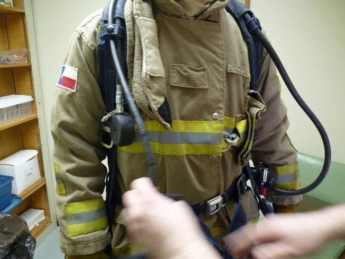
160 RTI International Donning Photos (RTI Test # 2225) 12


161 RTI International Donning Photos (RTI Test # 2225) 13


162 RTI International Pre-Test Photos (RTI Test # 2225) 14 Pre-test photos were taken prior to wind tunnel entry. To preserve air in the tank, the SCBA regulator was not connected until immediately before wind tunnel entry.
 15")


163 RTI International UV Photos: Head and Neck (Test # 2225, TP #7) 15 There were very heavy aerosol deposits on the neck, cheeks, ears, and hair due to penetration through the hood. The dark bands below the ears were relatively clean areas that were covered by the mask straps.
 16 The lower front")


164 RTI International UV Photos: Torso and Arms (Test # 2225, TP #7) 16 The lower front torso showed moderate to heavy aerosol deposits, and the location and pattern suggest infiltration through the coat-trouser interface. The bright spots on the hands and wrists could have been due to aerosol penetration, an artifact from doffing, or a combination of both.
 17")


165 RTI International UV Photos: Legs (Test # 2225, TP #7) 17 The lower legs had a high level of deposited aerosol. The patterns suggest aerosol infiltration through the boot-trouser interface and possible penetration through the trouser fabric.