IMPORTANT. Use of safety surfacing (wood mulch) in compliance with ASTM specification F1292 is required. WARNING
|
|
|
- Denis Harper
- 5 years ago
- Views:
Transcription

1 INSTALLATION DETAILS Recommended crew (Adult): 2-3 Installation time: 8-12 Hours not including concrete cure time User age: 5-12 Use zone: 22 Diameter Weight: 990 Actual Dimension: 120 Diameter MAINTENANCE: As the owner of the playground you are responsible for maintenance of the equipment and play area. A maintenance schedule must be developed and the equipment inspected frequently. Periodic Inspections, maintenance, repair and replacement of damaged parts is necessary for the safe operation and use of the equipment A maintenance section that includes component specific maintenance requirements is included at the end of this document. IMPORTANT WARNING Use of safety surfacing (wood mulch) in compliance with ASTM specification F1292 is required. UNIT IS DESIGNED FOR 12 OF ENGINEERED WOOD FIBER. USE OF ANY OTHER SAFETY SURFACING WILL VOID THE MANUFACTURERS WARRANTY AND COULD CAUSE AN INJURY. August 8,

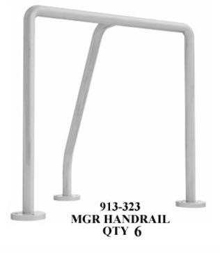
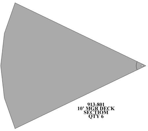
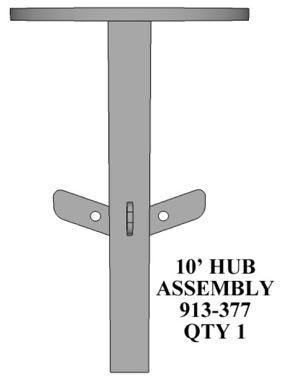
2 PARTS LIST ID PART # DESCRIPTION QTY MGR Quarter Deck MGR Handrail MGR Post Assembly Center Hub Disk for 10 MGR MGR Hub Assembly MGR Support Arm /2 Ball Bearing Grease Fitting Z 1/2 Flat Washer Zinc Z 1/2 Nylon Lock Nut Zinc /2 x 4 Carriage Bolt bps 3/8 x 1 1/4 Button Head Bolt /8 Flat Washer /8 Nylon Lock Nut bpk 7/32 Socket Key 2 16 Handrail Touch-up Paint /8 x 2 1/2 Button Head Bolt 6 NOTE: Keep a copy of these instructions on file to assist you with maintenance and replacement parts. IMPORTANT UNIT IS DESIGNED FOR 12 OF ENGINEERED WOOD FIBER. USE OF ANY OTHER SAFETY SURFACING WILL VOID THE MANUFACTURERS WARRANTY AND COULD CAUSE AN INJURY. August 8,

3 August 8,
4 FOOTING INFORMATION Total footing depth is 36 plus the height of the surfacing which is 12 for a total height of 48. The 36 includes 10 of blocking material, which in this case is dry concrete. So overall only 26 of the post assembly is inserted into the footing hole. See drawing on next page for footing/surfacing side view. It is the owner/installers responsibility to check local building codes and to comply with those codes. All footing depths listed here are recommendations and local soil types and frost lines may require a deeper and/or wider footing depth. If that s the case you must add more blocking material to accommodate the deeper footing, as the post length will still only be installed at the depth listed in this instruction manual. August 8,
5 August 8,
6 SPECIFICATIONS Deck 12ga HRPO welded steel deck Deck Coating Thermoplastic Handrail 30 high 1 5/8 od FloCoat galvanized steel tube welded to a 3/8 flange Handrail Coating Electrostatically applied and oven cured polyester powder coating Post Assembly 2 1/2 OD solid steel shaft with machined pocket for bearing. SPECIAL SAFETY & ASTM COMPLIANCE NOTES The deck height must be between 10 & 14 high from the safety surfacing for compliance INSTALLATION TIPS & TROUBLE SHOOTING UNIT IS DESIGNED FOR 12 OF ENGINEERED WOOD FIBER. USE OF ANY OTHER SAFETY SURFACING WILL VOID THE MANUFACTURERS WARRANTY AND COULD CAUSE AN INJURY. Do not completely tighten bolts until told to do so. When instructed tighten deck bolts incrementally as you move around the MGR to prevent gaps in between the deck sections. Stainless Steel hardware can occasionally be difficult to use particularly if you need to take them out to make an adjustment. It is recommended that you add a drop of oil to bolts that may have to be removed before you install them. Do not tighten bolts all the way until the unit is completely assembled and all components are square and level. Identify and separate all parts by referencing the detail drawings and the parts list. As you unpack and separate the components, use the cardboard sheets that were used for packing and shipping to prevent damage to the components. This is particularly true all Powder Coated and Thermoplastic coated components, by setting the components on top of the cardboard. August 8,
7 BEFORE YOU BEGIN In addition to the components on the packing list you will need a shovel, concrete, magnetic level and a socket or wrench set. INSTALLATION STEPS 1. Once the desired location has been determined while keeping a 22 dia use zone in mind, dig a 36" diameter hole to a depth of 36" 2. After all loose material is removed from the hole, add 10 of dry concrete to the bottom for the base. Place the post assembly (3) with the bearing pocket facing up and out of the hole. Plumb and level post NOTE: Post must be perfectly level in all directions before adding concrete for safety and durability of product. 3 Add concrete to hole, leave 2 of space in the hole below the surface grade for backfill. Crown the top of the concrete down and away from the post to help prevent water build up around the post. Periodically check the post to ensure it is level while concrete is curing. Wait a minimum of 48 hours before continuing installation. 4 After concrete has cured, place the Ball Bearing (7) into the pocket on the post and coat the post and bearing with general purpose grease. Next slide the Hub assembly (5) onto the post. (refer to detail A) 5 Attach the MGR support arms (6) to the hub assembly (5) by sliding the arm over the tabs on the hub (do not attach to the side of the tabs) and secure using 2 1/2 bolts, 3/8 washers and 3/8 nuts. (See Detail D) August 8,
8 6. When installing the deck sections (1) make sure NOT to place tab on support arm (6) in between the deck sections, tab should fit on the inside of the flanged side of the deck. Also, completely install all deck sections before tightening the bolts completely. When tightening the bolts move around the entire unit and tighten them evenly to ensure the deck sections are properly aligned and to ensure there are no gaps between the deck sections. Connect the support arm (6) to the deck sections as well as the deck sections to each other using 1 1/4 bolts (12), 3/8 washers and 3/8 nuts. (refer to Detail C for connecting the support arms to the decks and Detail G for connecting the deck sections) 7. Attach the Hub Disk (4) to the deck sections (1) and the Hub Assembly (5) by placing hub disk on top of the decks over the hub assembly and attach by inserting the 4 carriage bolts down through the decks and hub assembly. Secure from the bottom of the hub assembly with 1/2 washers and 1/2 lock nut. (see Detail E) 8. Attach the Handrails (2) to the Deck Sections (1) using 1 1/4 bolts, two 3/8 washers and a 3/8 lock nut. Nut should be located under the deck if properly installed. (see Detail F) 9. Governor Tension Adjustment: Back off the jamb nut on the governor assembly (attached to post assembly) and turn the adjustment nut until the rubber wheel is pushing firmly onto the sleeve of the hub assembly. Once wheel is firmly against the hub, tighten the jamb nut to secure it into position. (see Detail B) 10. Install surfacing to a depth of 12 inside the use zone. Taper surfacing under the deck down to the post to give access to the governor and grease fitting on the hub assembly. August 8,
9 EQUIPMENT MAINTENANCE Operational Grease Merry Go Round Weekly or daily in an environment that has sand or other small damaging materials. Hardware Inspect for loose or missing hardware. Tighten all loose hardware and replace all missing hardware. Block off access to equipment if necessary. Welds Inspect all welds for cracks. If a crack is found block access to the playground and contact your distributor for replacement parts immediately. Governor Inspect Governor weekly when greasing unit. Ensure that all pieces are installed and secure Ensure rubber wheel is in contact with the sleeve. If not, tighten by first backing off jam nut, tighten adjustment bolt until wheel is in position and then tighten the jam nut. Finish Inspect all metal components for coating damage. If powder coating needs to be repaired sand surface and mask off area. Coat with primer and once the primer has dried paint with color matching touch up paint. Contact distributor of color matching paint. Contact Distributor for Thermoplastic repair kit. Surfacing - Refer to the surfacing maintenance sheet provided by your surfacing supplier. Footings Inspect all footings to ensure equipment is secure. You must block access to prevent access until repair is made. Replacement Parts Reference the parts list on page 2 of the instruction set for this component to identify the part/s correctly. Contact your distributor to order parts. August 8,
10 EQUIPMENT MAINTENANCE INSPECTION FORM MAKE COPIES OF THIS FORM TO USE FOR INSPECTION REVIEW THE MAINTENANCE GUIDE IN THE APPENDIX TO BETTER UNDERSTAND THE IMPORTANCE OF MAINTENANCE AND HOW TO DEVELOP A MAINTENANCE SCHEDULE. DOCUMENT ALL MAINTENANCE ACTIONS ON THE LIST AS WELL AS ANY NOT LISTED. INCLUDE DATES AND SIGNATURES Inspect Governor Inspect Hardware Grease Shaft Inspect Finish Inspect Footing Inspect Surfacing Inspection Checklist Recommended Frequency Weekly Weekly Weekly Monthly Yearly Daily Grade (Pass/Fail/NA) Date Inspected Date Repairs Completed Inspector: Signature: Date: Maintenance Record Part Problem Corrective Action Date August 8,