Successful Foundation Preparations in Karst Bedrock of the Masonry Section of Wolf Creek Dam
|
|
|
- Rosemary Simon
- 5 years ago
- Views:
Transcription


1 Successful Foundation Preparations in Karst Bedrock of the Masonry Section of Wolf Creek Dam David M. Robison, P.G. Geotechnical and Dam Safety Section, Louisville District, U.S. Army Corps of Engineers US Army Corps of Engineers


2 Wolf Creek Dam Project Features Dam Embankment Lake Cumberland Concrete Gravity Section Switchyard Trout Hatchery 6 Unit Powerhouse 2


3 Wolf Creek Dam Location and Purpose Wolf Creek Location: Cumberland River in Russell County, Kentucky Authorized Purposes: Flood Control and Hydropower Additional Benefits: Navigation, Recreation, Water Supply, and Water Quality Reservoir first impounded in December


4 KarsticFoundation Cave Cave 4


5 KarsticFoundation 5


")
6 Dam and Foundation Profile Elevation (NGVD 29) Elevation (NGVD 29)

7 Masonry/Concrete Dam Upstream Profile 37 Monoliths 10 Tainter gates 37 x 50 each Embankment wrap-around Stair-step foundation 6 sluice gates 4 x 6 each 6 power intakes to turbines
8 Exploratory Grouting ( ) Legend 16 to 50 Gallons 50 to 100 Gallons > 100 Gallons

9 Dam Site Before Construction

 200")
10 Preliminary Borehole Exploration (1930 s) 200 ft. centers

11 Additional Early Borehole Exploration


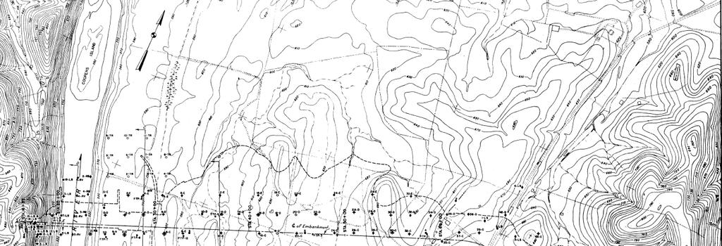
12 Bedrock Surface Contours


13 Preliminary Borehole Exploration (1940) LEIPERS CATHEYS Sandy clay filled cavities LEIPERS CATHEYS Cavity, probably clay filled LEIPERS CATHEYS LEIPERS CATHEYS LEIPERS CATHEYS Weathered shaly limestone LEIPERS CATHEYS LEIPERS CATHEYS LEIPERS CATHEYS Badly weathered & probably cavernous; Open cavity LEIPERS CATHEYS LEIPERS CATHEYS LEIPERS CATHEYS Weathered, fractured and cavernous; Cavity filled with clay, sand, and broken rock LEIPERS CATHEYS Cavity partially filled with sandy clay

14 Early Borehole Exploration


15 Overburden Removal

16 Overburden Removal


17 Additional Drilling Post- Overburden Removal

18 Additional Drilling Post- Overburden Removal

19 Blasting

20 BUILDING STRONG
21 Manual Removal of all Rock not Firmly Bedded

22 Rock Removal tower cableway skip pan

23 Bedrock Excavation Monoliths 37-30

24 Bedrock Excavation Monoliths 37-30

25 Bedrock Excavation Monoliths 37-30

26 Large Solution Channel Excavated

27 Second Channel with First

28 Solution Channel Cleaning

29 Solution Channel Cleaning

30 Bedrock Excavation Monoliths 29-25
31 Contact Grouting
")
32 Bedrock Excavation Monoliths (Power Intake Section)
33 Bedrock Excavation Monoliths (Power Intake Section)
34 Monolith 20 Grouting without Pressure


35 Bedrock Excavation Monoliths 18-14

36 Bucket Excavation Monoliths (Spillway Section)


37 Bucket Excavation Monoliths (Spillway Section)


38 Bedrock Excavation Monoliths 13-9 (Spillway Section River Channel)
39 Bedrock Excavation Monoliths 8-1 (Left Abutment)

40 Bedrock Excavation Monoliths 8-1 (Left Abutment)
41 Bedrock Excavation Monoliths 8-1 (Left Abutment)
42 Grout Holes and Drains
43 Grout Holes and Drains
44 Masonry/Concrete Dam Foundation Profile
45 Original Dam Construction Cost Original construction cost about $240 million in 2015 dollars Recent remediations of embankment cost about $600 million
46 Embankment Cross Section Impervious Rolled Fill Homogenous, well compacted, low plasticity clay. Drainage Blanket Choked with fines, difficult to distinguish from the alluvium in recent borings Cutoff Trench Compaction was likely variable. Placement and compaction, often by hand, occurred against rough vertical walls and under rock overhangs. Alluvium Predominately fine grained but with sand and gravel lenses Cutoff Trench Design Philosophy (Core Trench Foundation Report, 1943): Overhangs and loose rock will be removed only where they cross the lines of the trench, since the earthfill in the sides of the trench will have the function only of stability and not of an absolutely uniform tight contact with the trench walls. 46


47 Placement and Compaction of Cutoff Trench Fill 47

48 Distress Indicators Observed in the 1960 s At the time, there were no instruments to monitor the project. 48

49 Turbid Discharge into the Tailrace in


50 Sinkhole Observed near Switchyard in
51 Sinkhole Observed near Switchyard in


52 Solution Widened Joints Plan Legend Roadway ICOS Walls Barrier Wall 1960s Grout Lines 1967 Muddy Flow 1968 Sinkholes New Grout Lines Switchyard Grout Lines Top of Rock Contours - Elevation (ft)

53 Emergency Grouting Emergency Grouting ,000 cubic feet of solids injected 53


54 1975 ICOS Combination Wall 54

55 Downstream Wet Areas Wet Areas (shown in blue) (shown in blue) ICOS Since 1990 the extent of the wet areas has steadily increased, reaching the maximum extent in March of
56 March 09, 2010


57 Persistent Wet Areas
")


58 ACT Grouting ( ) 1300 holes 900,000 gallons of grout $70 million Completed September 2008 Double Line Grout Curtain 58


59 Barrier Wall Construction ( ) Total Length of New Barrier Wall: 3,800 feet 59

60 Barrier Wall Construction ( ) 60

61 Questions?