CEILING STRUCTURES BS 06, 07
|
|
|
- Leslie McKenzie
- 5 years ago
- Views:
Transcription
1 CEILING STRUCTURES BS 06, 07

2 Building physics basics ČSN :2011 U values Basic calculation to for exterior wall fit recommanded values! required values recommanded values recommanded for passive houses ext. wall roof flat roof floor at ground window tilt window door
3 Building physics basics ČSN :2011 R [m 2 K/W] thermal resistance λ [lambda] [W/(m.K)] coefficient of thermal conductivity U [W/(m 2 K)] heat transfer coefficient R se,si thermal resistance to heat transfer (surface) R=d/ λ U=1/(R se +R+R si ) R si 0,13 m 2 K/W (for single casing wall) R se 0,04 m 2 K/W (for single casing wall)

4 Horizontal Structures, Basic function, Requirements
5
6 CEILING STRUCTURES formwork drawing monolithic reinforced concrete monolithic RC with lost formwork prefabricated reinforced concrete composite reinforced concrete drawing layout of a precast structure
7 EXEMPLE formwork drawing in the scale 1:50 Represents a real shape of a concrete structure with basic dimensions view into the finished formwork just before pouring concrete in it
 finished and")
8 Vertical structures (load bearing walls) finished and formwork

9 Formwork assembly started

10 Formwork bottom finished

11 Reinforcement cladding

12 Pouring of concrete

13 Formwork disassembly
14 Formwork disassembly
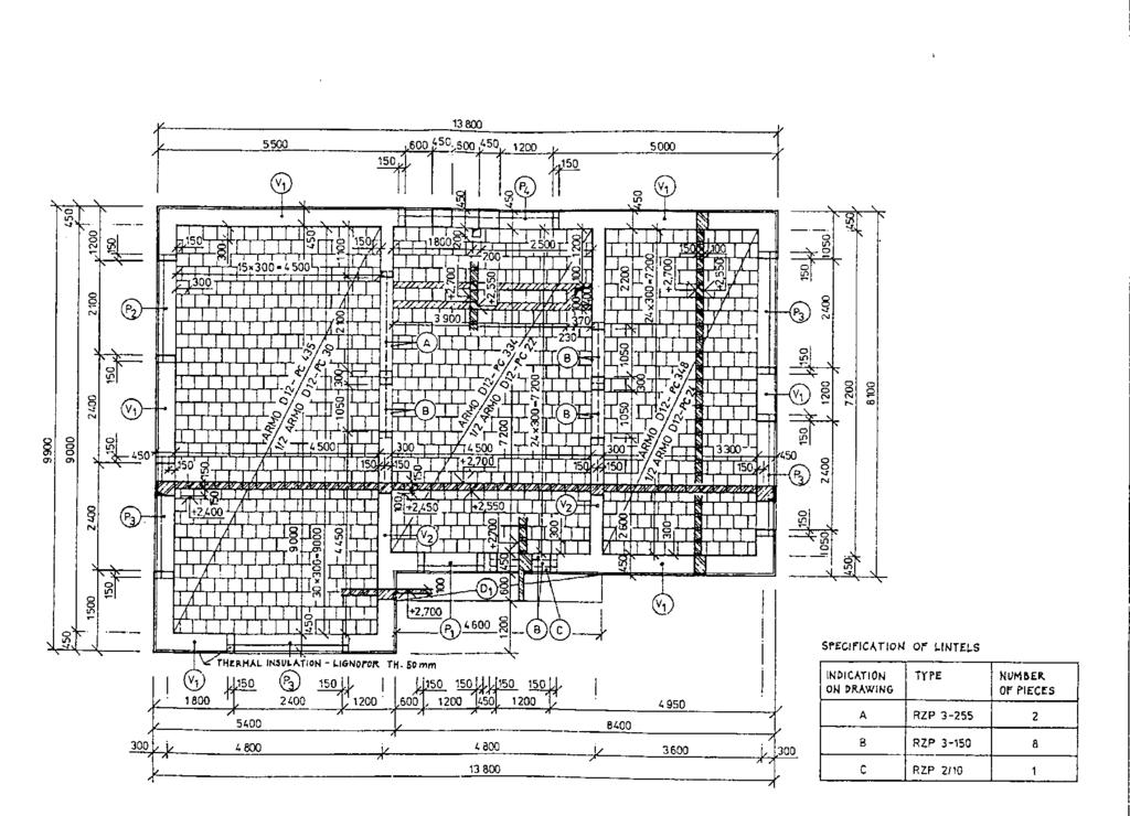
15 LAYOUT OF PRECAST CEILING STRUCTURE location of elements dimensions and shapes of constructions locations, dimensions and shapes of openings type of construction (element type) specification of used material
 outlines thick continuous, How to draw opening in ceiling structures openings by old Czech building code openings by new Czech building")
16 HOW TO DRAW CEILING STRUCTURES AND TYPE OF LINES visible lines and edges thin continuous line, invisible (hidden) thin dashed line, bearing structures (walls&columns) outlines thick continuous, How to draw opening in ceiling structures openings by old Czech building code openings by new Czech building code
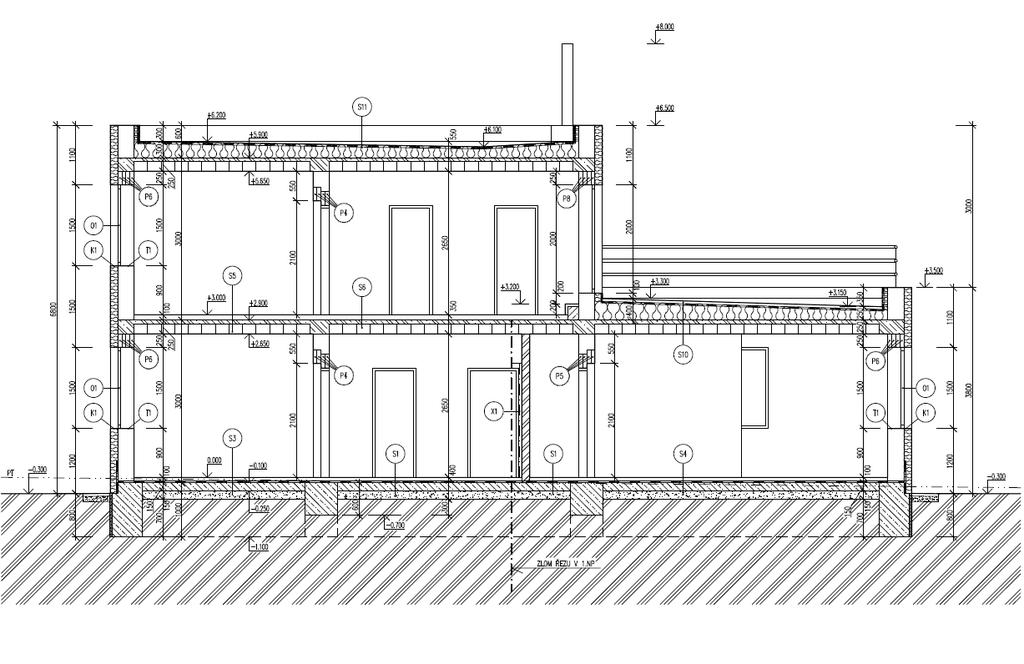
17 DRAWING CONDATIONS OF CEILING STRUCTURES EXAMPLE OF PLAN AND DOWENSWEPT SECTION OF CEILING STRUCTURE
18 CEILING STRUCTURES DRAWING CONDATIONS OF CEILING STRUCTURES
19 Elements signs Each element (wall, column, floor slab) has there own sign made from big letter and number i.e. C1, W3 etc. vertical elements signs are in a square: C1, column no.1 horizontal elements signs are in a circle: S2... slab no.2 the area of slabs is signed with a diagonal crossing the element reinforcement orientation is symbolised by arrows
20 folded section outlines full thick bearing structures outlines full thick CZECH TECHNICAL UNIVERSITY IN PRAGUE DEPARTMENT OF BUILDING STRUCTURES visible lines and edges full thin openings floor girder slab (D1) horizontal elements signs in a circle column slabs main reinforcement orientation vertical elements signs in a rectangle
21 floor girder column slab (D1) EXEMPLE plan of mounted ceiling structure
22 EXEMPLE MONOLITHIC CEILING STRUCTURE
23 EXEMPLE MONOLITHIC CEILING STRUCTURE
24 EXEMPLE MONOLITHIC CEILING STRUCTURE
25
26 EXEMPLE OF PLAN AND DOWENSWEPT SECTION OF CEILING STRUCTURE
27 EXAMPLE OF PLAN AND DOWENSWEPT SECTION OF MONOLITHIC CEILING STRUCTURES


28 CEILING STRUCTURES monolithic RC with lost formwork

29 Floor structures prefabricated reinforced concrete Precast RC beam floors - placed side by side
30 Floor structures prefabricated reinforced concrete Precast RC floors from panels -vyroba-stropni-panely.php


31 Floor structures prefabricated ceramic-concrete Precast RC floors from panels

32 Floor structures prefabricated reinforced concrete Precast RC floors from panels prestressed hollow panels


33 Floor structures composite reinforced concrete Composite RC floors from ribs and fillers

34 Floor structures composite reinforced concrete Composite RC slab floors
35 Excercise alternative drawing of layout of precast structure (scale 1:50)
36 Signs for elements Each element (wall, column, floor slab...) has its own sign made from big letter and number i.e. C1, W3 etc. vertical elements signs are in a square: C1... column no. 1 horizontal elements signs are in a circle: S2... slab no. 2
37 Example panel prefabricat with openings
38 Example 2 Commercial building
39 Example of plan and section of mounted ceiling structure
40 Example of concret finished in mounted ceiling structure

41 STRUCTURAL DESIGN: LOAD BEARING SYSTEM, MATERIALS LBS IS COMPOSED OF VERTICAL AND HORIZONTAL STRUCTURES: VERTICAL STRUCTURES: BEARING WALLS, BEARING COLUMNS VIA LECTURE 2. HORIZONTAL STRUCTURES: CEILING, FLOORS, ROOFS Lecturer: Ing. Malila Noori, Ph. D.

42 HORIZONTAL STRUCTURES AND TYPICAL DIMENSIONS


43 HORIZONTAL STRUCTURES AND TYPICAL DIMENSIONS

44 HORIZONTAL STRUCTURES AND TYPICAL DIMENSIONS

45 HORIZONTAL STRUCTURES AND TYPICAL DIMENSIONS

46 HORIZONTAL STRUCTURES AND TYPICAL DIMENSIONS

47 HORIZONTAL STRUCTURES AND TYPICAL DIMENSIONS
48 HORIZONTAL STRUCTURES AND TYPICAL DIMENSIONS
49 HORIZONTAL STRUCTURES AND TYPICAL DIMENSIONS
50 HORIZONTAL STRUCTURES AND TYPICAL DIMENSIONS

51 HORIZONTAL STRUCTURES AND TYPICAL DIMENSIONS
52 HORIZONTAL STRUCTURES AND TYPICAL DIMENSIONS
53 HORIZONTAL STRUCTURES AND TYPICAL DIMENSIONS
54 STEEL CONCRETE LINTEL INDIVIDUAL LINTEL CONTINUOUS LINTEL CONTINUOUS LINTEL WITH WREATHS EXAMPELS OF CERAMIC MOUNTED LINTEL
55
56
57
58 FIG. 3 - EXAMPLE OF PLAN AND DOWENSWEP T SECTION OF CEILING STRUCTURES
59 OVERHEAD TRACK CONSTRUCTION DRAWING
60
61

62
63 EXAMPLES OF PLAN AND SECTION OF CEILING STRUCTURES PLAN AND SECTION OF DEFRENT KIND OF CEILING STRUCTURES
64 EXAMPLE OF SLABS WITH DEFRENT WAYS
65 EXAMPLE OF SLABS WITH DEFRENT WAYS
66 PANEL OF CEILING STRUCTURES
67 SAMPLE OF FLOORS OF PREFABRICATED ELEMENTS
68 EXAMPLE OF BEAM AND CSD HURDIS CEILINGSTRUCTURES
69