Construction of the Asset Polymer Composite Bridge for Heavy Traffic Loads
|
|
|
- Susanna Morris
- 5 years ago
- Views:
Transcription

1 Construction of the Asset Polymer Composite Bridge for Heavy Traffic Loads Björn Täljsten Professor, Technical University of Denmark, Lyngby, Denmark and Luleå University of Technology, Luleå, Sweden 1
2 Outline Introduction Background Composite deck Composite girders Comparison Theory/Tests Bridge construction Loading field test Summary and Conclusions Acknowledgements 2
3 Introduction Drivers for FRP composites in bridges FRP composites have the following potential advantages in bridge construction: Reduced mass: Easier, faster and more economic installation - smaller cranes required Ability to bring larger sections to site reducing assembly time and cost Less disruption during installation Reduction in size and cost of supporting structure, bearings, cables, etc Reduced energy in transportation to site 3
4 Introduction Advantages of FRP composites in bridges, cont. Superior durability: Resistant to atmospheric degradation, de-icing salts, chemicals from spillages, etc Reduction in maintenance requirements, through-life costs and disruption Ability to mould complex forms: New aesthetic possibilities Geometrically more efficient solutions Desirable electrical and thermal properties: Can be electrically non-conductive (without carbon fiber), which may be advantageous near electrical installations such as railway lines 4

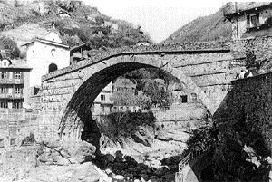
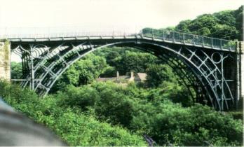


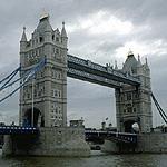


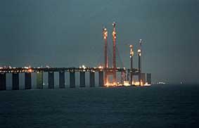

5 Introduction Stone Cast iron compression Cast iron tension Advanced composites Straw/mud Reinforced concrete Reinforced concrete Stone/brick compression Stay cables Construction has followed the evolution in materials 5
 Client Oxfordshire CC Academia KTH IETCC Surfacing Supplier HIM Coordinator Mouchel Manufacturer Fiberline Contractor Skanska Academia")
6 Background Acronym: ASSET (Advanced Structural SystEm for Tomorrows Infrastructure) Client: European Commission Architect: N/A Category: Civil (optionally Project Development) Value USD: 4,5 million (50% EC funding) Client Oxfordshire CC Academia KTH IETCC Surfacing Supplier HIM Coordinator Mouchel Manufacturer Fiberline Contractor Skanska Academia LTU 6

7 7
8 Background The ASSET profile used for bridge deck.manufactured by the pultrusion process, Fiberline Denmark. Square profiles reinforced by carbon fibres used for loadcarrying beams. Special profiles used for side paneling Each of the four main supporting beams, 520 x 480 mm, are constructed of four profiles reinforced by glass and carbon fibres and bonded together. The decking system bonded together are positioned and glued onto the supporting beams. The profiles can be mounted on concrete beams as well as on steel beams. The side paneling consist of maintenance-free and corrosion-resistant high composite profiles. The edge beams, footpath and the two crossbeams at each end of the bridge are made of concrete, whereas the crash barrier is made of steel. The wearing surface is made of polymer concrete, but asphalt is also an option. 8
9 Background - Technical Data Bridge size: Traffic Capacity: 10m span x 6.8m width over the River Cole, on the B4508, in Oxfordshire ASSET profile designed for full UK and European traffic loading, including concentrated wheel loads Structure: 34 no. ASSET profiles made from glass fibre and spanning transversely between 4 no. carbon fibre/glass fibre composite main beams, 11m long and spaced 2m apart; bridge abutments and parapets consist of conventional reinforced concrete construction. Adhesive: Deck created by adhesive bonding 34 ASSET profiles side by side; bonded using an epoxy adhesive to the main beams; composite main beams consist of 4 GFRP square hollow sections bonded together plus CFRP resin infused to the top and bottom flanges for additional flexural rigidity. Weight: Total bridge weight approx. 37 tonnes; composite components approx. 12 tonnes - a third of the weight of a reinforced concrete bridge of the same dimensions and load capacity. Weight of the bridge deck 100 kg/m 2. Construction: Bridge deck will be constructed and bonded in an environmentally controlled site factory adjacent to the existing bridge. Complete with concrete diaphragms and parapets, will be lifted in place onto the bridge bearings using a medium sized crane Surfacing: Polymer concrete and epoxy-based wearing surface 9


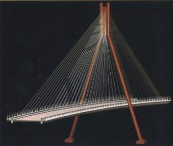
10 Background The new prototype bridge High degree of innovation Connection details The Original West Mill Bridge Surfacing and bridge deck Fascia panel Composite girders The New West Mill Bridge 10

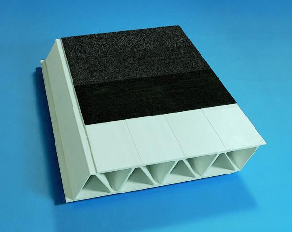
11 Pultrusion Bridge Deck ASSET Profile Bonding Sub-decks 11


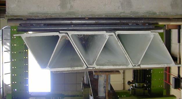
12 Bridge Deck Testing of single profile Testing of Sub-decks 12
13 Composite Girders Manufacturing of West Mill Composite Beams Theoretical calculations Full-scale manufacturing Full-scale design Proof-testing 13

14 Composite Girders Manufacturing of prototype girders Outlet, placed at the centre of the beam, 2 m to each end. Reinforcement, flow-layer and parting-film Bag Inlet, dia 16 mm, along the whole beam Grinding of surfaces Selant Selant Assambly of GFRP profiles Gridning of flanges Vacuum infusion of carbon fibre fabric Glass fibre Carbon fibre 14
![Load, F, [kn] 204 LULEÅ UNIVERSITY OF TECHNOLOGY Composite Girders Testing of prototype girders 2600 201 P/2](/docs-images/92/109510198/images/15-1.jpg "P/2 700 600 250 LVDT 4 A B LVDT 3 LVDT 6 LVDT 7 LVDT 1, 2 A 2000 B 250 Beam 2: Carbon STG 7 Section A-A")

15 Load, F, [kn] 204 LULEÅ UNIVERSITY OF TECHNOLOGY Composite Girders Testing of prototype girders P/2 P/ LVDT 4 A B LVDT 3 LVDT 6 LVDT 7 LVDT 1, 2 A 2000 B 250 Beam 2: Carbon STG 7 Section A-A Section B-B STG 12 Section A-A STG Section B-B 150 Buckling under the load 4, 5, 6 STG 9, 10, 11 STG 4, 5, 6 STG 9, 10, STG 8 STG 13 STG 8 Beam 1 Beam Mid-deflection,, [mm] 15


16 Composite Girders Full-scale Manufacturing Applying adhesive Vacuum pressure is applied resin is moving Just before applying pressure to the beam Removing the vacuum infusion system 16
17 Composite Girders Proof-testing P P LVDT 5 LVDT 4 A LVDT 3 A LVDT 1, 2 Section A-A STG 1 STG 2 STG 3, 4, 5 STG ca 25 STG 7 Beam A Beam B Beam C Beam D ca 25 17
![Load, F, [kn] Beam height, h, [mm] Composite Girders Proof-testing 600 500 400 50 kn 100 kn 200 kn 300 kn 348 kn 300 500 Beam A](/docs-images/92/109510198/images/18-1.jpg "200 400 100 300 200 0-1500 -1000-500 0 500 1000 1500 Strain distribution,, [ s] 100 0 0 10 20 30 40 50 60 Mid-deflection,, [mm]")
18 Load, F, [kn] Beam height, h, [mm] Composite Girders Proof-testing kn 100 kn 200 kn 300 kn 348 kn Beam A Strain distribution,, [ s] Mid-deflection,, [mm] 18
19 Load, F, [kn] LULEÅ UNIVERSITY OF TECHNOLOGY Comparison Between Theory and Test 500 Beam A Model Mid-deflection,, [mm] P test, [kn] test, [mm] (EI) test, [Nm 2 ] (EI )theory, [Nm 2 ] Beam A Beam B EI theory theory L flexure 2 PL a 2 PL a 4a 3 48 EI 2 L 2 4a 2 theory s G s Pa A mod web flexure Beam C Beam D E E CFRP 3 I th 4t h t GFRP C h 2 tc 4 htc h
20 Bridge s Construction Different suggestions for bridge furniture and connection 20
21 Bridge s Construction Solution for the edge beam and end fascia 21


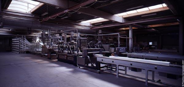
22 Bridge s Construction A large amount of work was focussed on the bonding process Pre-bonding Sub-decks Work site Bonding was performed indoor in a site factory 22


23 Bridge s Construction Bonding the sub-decks together and then to the composite girders 23


24 Bridge s Construction Adding end fascia to ASSET decking, then filling with concrete Grinding and cleaning Edge beam End fascia 24

25 25

26 26

27 27

28 28

29 29

30 30

31 31


32 Loading test To verify theoretical calculations load tests were undertaken 32


33 Loading test FOS attachment to the deck and beams 33

34 Loading test Truck driven centrally on the bridge stopping at every meter Level of strain reflects position of sensors relative to loading FBG1 Tempereture sensor FBG2 Right end FBG FBG3. FBG4. FBG5. FBG6. FBG7. FBG8 Left end FBG Strain ( ) :41:35 14:53:37 15:03:38 15:13:39 15:23:41 Time (hh:mm:ss) 34


35 Future of ASSET New GFRP Bridge across UK motorway Rapid construction and reduced disruption for road users were important considerations in the decision of the UK Highways Agency to span the M6 motorway in Lancashire with a new lightweight bridge made of GRP composite The innovative bridge, which is 52 metres long and built using the ASSET bridge deck profiles, is two-thirds the weight of the one it replaces, but is stronger and offers cost savings through reduced future maintenance. The motorway bridge replaces a 40-year-old life-expired bridge and is designed to carry vehicles up to 40 tonnes. The Highways Agency points out that the new bridge has a superior strength/weight ratio to steel or concrete and is non-corrosive to water and salt 35
36 Future of ASSET The Highways Agency wishes to promote wider use of GRP and stimulate further development of the technology, thereby paving the way for improved cost effectiveness. Wider experience of the materials is needed by the construction industry. And, as with all construction, workmanship is a key issue. The Highways Agency will also consider widening the application of GFRP to other infrastructure applications. The Agency believes that accelerating the use of GFRP will have major benefits in future motorway widening schemes and bridge rehabilitation across the network. 36
37 Conclusions Many details discussed before the bridge s final solution Sections bonded Tests show excellent bond force transfer GFRP composite girders with CFRP flanges Vacuum infusion technique used Bonding procedure time consuming can be improved Normal construction works for the retaining walls and abutments The process of construction can be speeded up Acknowledgement The authors want to acknowledge the European Commission for funding and all the participating partners for their contribution to the project 37