MARINE WORKS SHAFA AL NAHDAH SHAFA AL NAHDAH. shafaconstruction.com. SHAFA - UAE (HEAD OFFICE) SHAFA Al Nahdah Building Contracting LLC
|
|
|
- Rodney Hawkins
- 5 years ago
- Views:
Transcription
1 MARINE WORKS shafaconstruction.com SHAFA AL NAHDAH SHAFA - UAE (HEAD OFFICE) SHAFA Al Nahdah Building Contracting LLC Al Manara Tower, ETA Star 23rd Floor, Office no , Business Bay, P.O. Box Dubai-UAE T: F : E: info@shafaconstruction.com W: shafaconstruction.com SHAFA AL NAHDAH
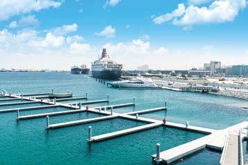
2 CONTENT Rock Revetment Mina Rashid Marina-Design & Build Access to Pontoons 4-5 Boat Ramp Marina Road 6-7 Tubular Piles Final Stage of Phase I & II 8-9 Pontoons Fabrication & Casting Quay wall Berth 9 - Mina Port rashid Launching The Pontoons Coastal Berth Mooring Dolphin - Mina Rashid Installing Pontoon Accessories Presidential Jetty- Aden Yemen 0-1 Content 2-3


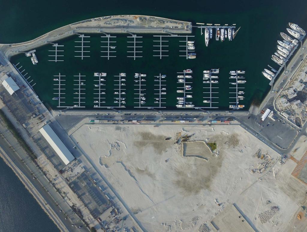
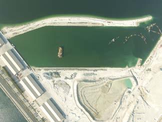
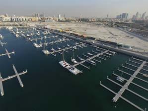
3 MINA RASHID MARINA-DESIGN & BUILD Initial Stage- Dredging Client DP World Consultant MAPES Engineering Co. Ltd Date of Start Location Port Rashid - Dubai, UAE Built Up Area 114,500 Duration 22 Months
 West Boat Ramp (L) 70.")
 at the bottom side of")
 over the geotextile & installation of precast")

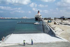
4 BOAT RAMP Total Quantity of Ramps: 2 East Boat Ramp (L) 70.6m x 20m (w) West Boat Ramp (L) 70.6m x 20m (w) Excavation & trimming of the existing soil at the end block area Installation of geotextile, secondary rock (10 to 20 kg) at the bottom side of the end block Excavation, trimming & installation of geotextile at ramp area Crushed aggregate (20mm) over the geotextile & installation of precast concrete over the aggregates Installation of side support end precast concrete block at both sides of precast slab Installation of armor rock at the sides of side support precast blocks Cast in-situ final end block construction

 mobilization at site")


5 TUBULAR PILE Total Number of Piles 324 Nos. Phase I Piles Phase II Piles Tubular Pile Driving Works Tubular Pile & Pile driving equipment s (Floating barge, Tug Boat, Pile driving equipment s) mobilization at site Lifting and installation of the pile at pile driving equipment Setting out of the floating barge at exact position with the help of surveyor from the land and GPS Starting the Pile driving with the help of hydro hammer, this will be operated by crane operator Pile head cutting


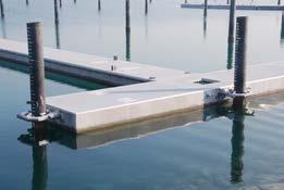
6 PONTOON FABRICATION & CASTING Total Number of Pontoons: 222 Primary, Secondary & Landing Pontoon: 20 M X 2.5 M Finger Pontoon:15m x 1.5m & 20m x 1.5m Dock Pontoon: 10m x 5.0m Pontoon Casting Pontoon Fabrication material delivery EPS ( Expandable Polystyrene Styrofoam) block protective coating works Epoxy coated wire mesh & rebar rabrication Installation of EPS block, wire mesh & rebar Installation of pontoon embedded items Pontoon shutter installation & alignment of embedded material Pontoon concrete pouring works and curing works


7 LAUNCHING THE PONTOONS Launching The Pontoons Concrete pontoon shifting from casting yard to launching yard Arrangement of all lifting tools Launching of concrete pontoon Dragging of concrete pontoon to desired location installation


8 INSTALLING PONTOON ACCESSORIES Installing Pontoon Accessories Installation of rubber fender Installation of pile guide Cleat and checkered plate Installation of dock identification number Installation of MEP utility and SOS pedestal. Pile Cap


 at toe & slope area around 30 cm depth as per the survey")
 Installation of precast end")
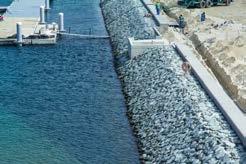
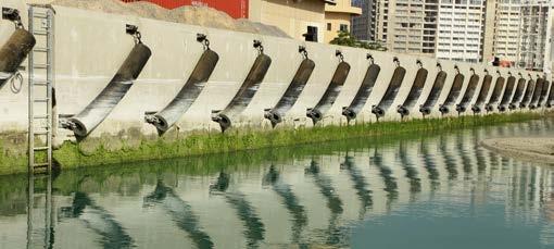
9 ROCK REVETMENT Total Length of Revetment Works Km Primary One Layer kg Secondary Two Layers kg Rock Revetment Construction Excavation, trimming of the excavated soil at slope area & Toe area Installation of geotextile in toe & revetment slope area Installation of secondary rock ( 10 to 20 kg ) at toe & slope area around 30 cm depth as per the survey alignment Installation of the primary rock (70 to 180KG) at slope area (under & above the water) Installation of precast end concrete block (capping beam)


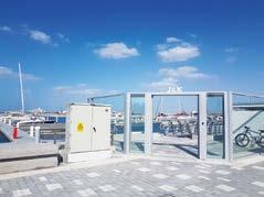
10 ACCESS TO PONTOON Access platform concrete works Handrail & glass door installation Aluminum gangway Erection Works Finishing works


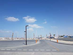
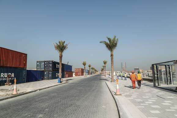
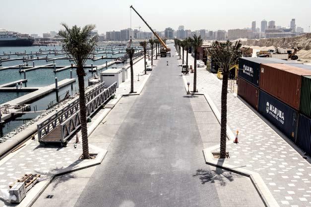
11 MARINA ROAD Site survey, road line, utilities service marking and leveling etc. Bottom soil trimming, grading and compaction. Laying of underground service duct pipes with necessary manhole construction, street light foundation. Installation of road drainage system. Installation of kerb stone & capping beam. Spreading of road base material in layer wise with proper compaction. Fixing of Inter lock, paving block including sand bedding for walkway and drive way. Proper compact the interlock with sand. Palm tree and street light installation. Finally, road marking and fixing of road signage for smooth usage.


12 FINAL STAGE OF PHASE I & II


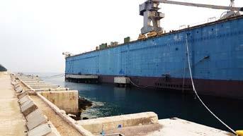
13 QUAY WALL REFURBISHMENT WORKS Client: DP WORLD Consultant: ITD Consultant Date of Start: June 2013 Location: Port Rashid - Dubai, UAE Builtup Area: 1,100 m Duration: 7 months Initial stage: existing quay wall concrete breaking Rebar installation Installation of steel shutter Reinforcement Form works installation Concrete pouring Curing of concrete Installation of rubber fender, ladder & mooring ring


14 COASTER BERTH MOORING DOLPHIN Client: DP WORLD Date of Start: 2018 Location: Port Rashid - Dubai, UAE Builtup Area: To Berth 162m Mega Yatch Duration: 4 months Tubular pile driving works Tubular pile dynamic load test Tubular pile head cutting Bottom support steel channel & form works installation Steel reinforcement installation Embedded material installation for the fenders Concrete pouring Concrete curing Pneumatic fender & strip fender installation Tubular pile cathode protection works Safety handrail installation

 190m long breakwater structure (armor rocks,")
.")


15 PRESIDENTIAL JETTY Client: Ministry of Construction Date of Start: 10th Jan 2007 Location: Aden Yemen Equipment used: Batching Plant & 130ton Crane Builtup Area: 7,000m 2 Duration: 10 months Design & construction: 190m accropodes breakwater 100m quay wall for presidential yacht berthing Infrastructure & Quay furniture (Untilities, Cabinets, Bollards, Fenders, High Masts Lighting) 190m long breakwater structure (armor rocks, accropodes and retaining wall) against the open water on up to 5m of water and with a m berthing facility on the protected side with 2 respectively 3 meters water depth, (block quay wall). Retaining wall was designed for overtopping and the elements were placed on a 0.1m bed of crushed material which in turn were protected against washing out. Block wall quay was designed for a Water level of CD, with the fill behind the wall having a friction angle of 35 deg. The bed consisted of or 0 75 mm crushed material, placed on a heavy duty geo-textile. Blocks during placing were given a slight back fall against the bund and each column given a slight back fall towards the previous.