FABRICATED BRIDGE PRODUCTS CATALOG
|
|
|
- Ilene Shepherd
- 5 years ago
- Views:
Transcription


1 FABRICATED BRIDGE PRODUCTS CATALOG

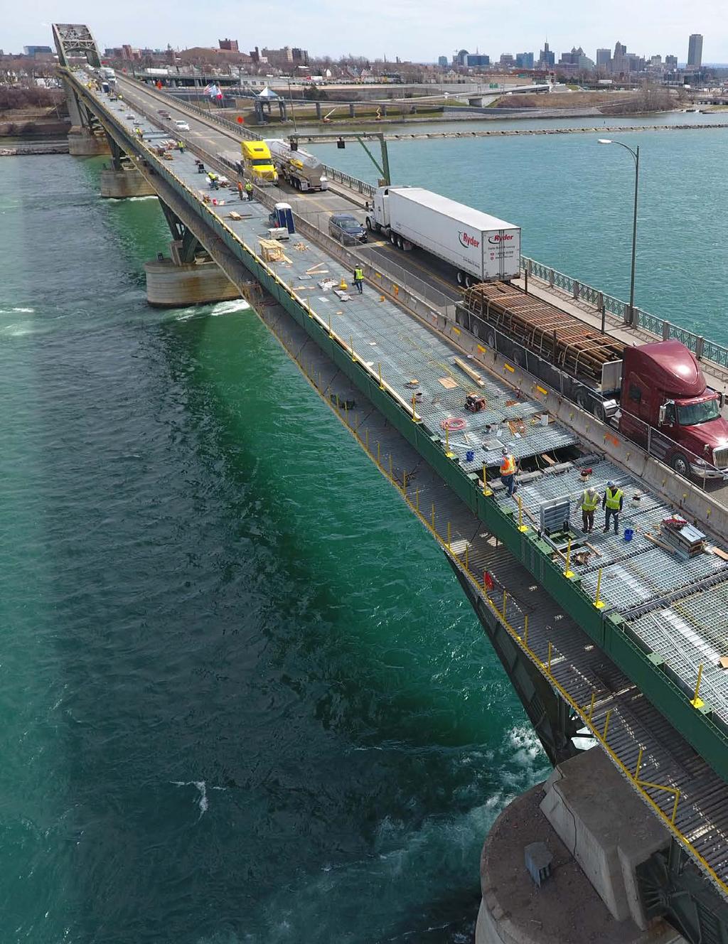
2 CONTENTS INCLUDE: - Steel Bridge Grid Decking - Stay-in-Place Metal Bridge Deck Forms - Aluminum Bridge Decking - Bridge Railing Systems Project Photo: Peace Bridge, Buffalo, NY

3 WELCOME TO L.B. FOSTER COMPANY L.B. Foster Fabricated Bridge Products produces steel grid bridge decking, bridge railings, stayin-place metal bridge deck forms and miscellaneous fabricated bridge components. Our history can be traced back to the first use of steel grid bridge deck products in the early 1930 s. Our financial strength and stability sets us apart from our competition and makes us uniquely suited to take on large jobs with extended contract duration. L.B. Foster s combined decades of experience in our sales, engineering and project management groups ensures that your project will receive the professionalism you need to help make it a success. Our AISC-certified plants use lean manufacturing procedures to keep costs low and ensure high product quality. When it comes to steel grid bridge decking, we have the largest production capacity in our industry. Our ability to execute on large complex projects has been proven time and again on thousands of projects and millions of square feet of product produced.


4 5-Inch 4-Way Modified Open Grid desirable deck features of fatigue resistance, ride quality and stiffness are maintained or improved. The standard modified grid is available with the 5 3/16 x 5.3# main beam spaced on 7 ½ centers. Material is either 50-ksi or 50-ksi weathering steel. Product specifications available upon request. Visit lbfoster.com Typical Details: 5-Inch 4-Way Modified L.B. Foster s 5-Inch 4-Way Modified was developed to meet increasing performance and reliability needs, as highway traffic volumes and truck loadings continue to grow, without adding additional deck dead load. Open grid design durability is linked directly to transverse stiffness the ability to transmit load from one main beam to adjacent ones. To provide increased transverse stiffness, Foster configured its main beam to permit use of a deeper/stiffer distribution bar. The modified grid delivers trans-verse stiffness increases of 50% or more, greatly improving load distribution and reducing localized stresses. This grid maintains the 4-Way design style so the SECTION B-B SECTION A-A 5-Inch 4-Way Modified Properties Table 5.4-M Style / Main Beam Size & Spacing 50 ksi Steel Max Continuous Section Modulus (in3/ft)* Clear Span HS25 Wheel Load Top Bottom L/800 Deflect 27 ksi Stress Approximate** Weight (lbs/sf) 4 Way M / ft 6.71 ft 18.5 * Section modulus based on 50% of the diagonal bars active. ** The deck weight psf is based on an uncoated standard panel width of 7 8, actual weights may vary due to panel widths used, coating weight and deck attachments. WARNING: Uncoated-weathering steel provides the best skid resistant open grid surface. Galvanized or painted coatings can reduce the skid resistance. Vertical and/or horizontal curves on the bridge decking can increase lateral forces on vehicles, further reducing skid resistance efficiency. It is recommended that lane changes be prohibited and appropriate speed limits be strictly enforced to promote safety. Various studies are available upon request.

5 5-Inch 4-Way HD Modified Open Grid APPLICATION GUIDELINES Modified deck. The high deck stiffness results in improved load and stress distribution throughout the grid network reducing localized stresses. The grid is available with the 5 ³/16 x 5.3# main beam spaced on 3 ³/₄ centers. Material is either 50 ksi or 50 ksi weathering steel. Product specifications available upon request. Visit lbfoster.com Typical Details: 5-Inch 4-Way HD Modified L.B. Foster s 5-Inch 4-Way HD Modified is the highest evolution in open grid design. It is engineered to provide the highest level of reliability for the heaviest and most intense loading conditions, even on longer spans. HD Modified combines the best design features of all other 4-Way designs including diagonal bars, deeper/stiffer cross bars and closely spaced main beams. These features all work together in the HD Modified to provide the top-of-the-line open grid on the market today. SECTION B-B No other open grid can deliver the longitudinal, transverse and torsional stiffness of the HD 5-Inch 4-Way HD Modified Properties Table 5.4-HM Style / Main Beam Size & Spacing 50 ksi Steel Max Continuous Section Modulus (in3/ft)* Clear Span HS25 Wheel Load Top Bottom L/800 Deflect 27 ksi Stress Approximate** Weight (lbs/sf) 4 Way / ft 7.41 ft 25.8 * Section modulus based on 50% of the diagonal bars active. ** The deck weight psf is based on an uncoated standard panel width of 7 8, actual weights may vary due to panel widths used, coating weight and deck attachments. WARNING: Uncoated-weathering steel provides the best skid resistant open grid surface. Galvanized or painted coatings can reduce the skid resistance. Vertical and/or horizontal curves on the bridge decking can increase lateral forces on vehicles, further reducing skid resistance efficiency. It is recommended that lane changes be prohibited and appropriate speed limits be strictly enforced to promote safety. Various studies are available upon request.


6 5-Inch RB 4.2M Open Grid lower traffic volume structures where the 4-Way style grids may not be required. However, the close spaced main beam design permits its use on longer spans and for heavy loads. Product specifications available upon request. Visit lbfoster.com Typical Details: 5-Inch RB 4.2M L.B. Foster s 5-Inch RB 4.2M is designed to provide increased load carrying capability and longer span capacity compared to the lighter RB 6.2M and RB 8.2M open grid designs. It s 4 spaced main beams and two supplemental bars yield a more balanced section than RB 3.0M resulting in greater load and span capabilities with no added weight. SECTION B-B The Modified grid delivers trans-verse stiffness increases of 50% or more when compared to the outdated 2 deep cross bars offered on some older open grid designs. The deeper cross bars greatly improve load distribution and reduce localized stresses. This rectangular patterned deck is suitable for SECTION A-A 5-Inch RB 4.2M Properties Table 5.4.2M Style / Main Beam Size & Spacing 50 ksi Steel Max Continuous Section Modulus (in3/ft)* Clear Span HS25 Wheel Load Top Bottom L/800 Deflect 27 ksi Stress Approximate** Weight (lbs/sf) RB 4.2 M / ft 8.48 ft 25.4 * Section modulus based on 50% of the supplemental bars active. ** The deck weight psf is based on an uncoated standard panel width of 8 2, actual weights may vary due to panel widths used, coating weight and deck attachments. WARNING: Uncoated-weathering steel provides the best skid resistant open grid surface. Galvanized or painted coatings can reduce the skid resistance. Vertical and/or horizontal curves on the bridge decking can increase lateral forces on vehicles, further reducing skid resistance efficiency. It is recommended that lane changes be prohibited and appropriate speed limits be strictly enforced to promote safety. Various studies are available upon request.

7 5-Inch RB 6.2M Open Grid APPLICATION GUIDELINES improve load distribution and reduce localized stresses. If the superior 4-way riding surface is not required, this design is suitable for use on low speed, low to moderate traffic volume structures where the ADTT and deck spans are modest. Product specifications available upon request. Visit lbfoster.com Lighter Typical Details: 5-Inch RB 6.2M L.B. Foster s 5-Inch RB 6.2M is the most commonly used of the RB series rectangular patterned open grids. RB 6.2M offers the best compromise of deck weight to load and span capability for the RB style rectangular patterned decks. Open grid design durability is linked directly to transverse stiffness the ability to transmit load from one main beam to adjacent ones. To provide increased transverse stiffness, Foster configured its main beam to permit use of a deeper/stiffer distribution bar. SECTION B-B The modified grid delivers trans-verse stiffness increases of 50% or more when compared to the outdated 2 deep cross bars offered on some older open grid designs. The deeper cross bars greatly 5-Inch RB 6.2M Properties Table 5.6.2M SECTION A-A Style / Main Beam Size & Spacing 50 ksi Steel Max Continuous Section Modulus (in3/ft)* Clear Span HS25 Wheel Load Top Bottom L/800 Deflect 27 ksi Stress Approximate** Weight (lbs/sf) RB 6.2 M / ft 6.59 ft 19.2 * Section modulus based on 50% of the supplemental bars active. ** The deck weight psf is based on an uncoated standard panel width of 7 8, actual weights may vary due to panel widths used, coating weight and deck attachments. WARNING: Uncoated-weathering steel provides the best skid resistant open grid surface. Galvanized or painted coatings can reduce the skid resistance. Vertical and/or horizontal curves on the bridge decking can increase lateral forces on vehicles, further reducing skid resistance efficiency. It is recommended that lane changes be prohibited and appropriate speed limits be strictly enforced to promote safety. Various studies are available upon request.


8 5-Inch RB 8.2M Open Grid improve load distribution and reduce localized stresses. If the superior 4-Way riding surface is not required, this design is suitable for use on low speed, low to moderate traffic volume structures where the ADTT and deck spans are modest. Product specifications available upon request. Visit lbfoster.com Lighter L.B. Foster s 5-Inch RB 8.2M is generally recommended for light duty and / or temporary applications with shorter span lengths and lighter loads. RB 8.2M offers a less expensive alternative where a more heavy duty deck is not required. Open grid design durability is linked directly to transverse stiffness, the ability to transmit load from one main beam to adjacent ones. To provide increased transverse stiffness, Foster reconfigured its main beam to permit use of a deeper/stiffer distribution bar. Typical Details: 5-Inch RB 8.2M SECTION B-B The Modified grid delivers transverse stiffness increases of 50% or more when compared to the outdated 2 deep cross bars offered on some older open grid designs. The deeper cross bars greatly 5-Inch RB 8.2M Properties Table 5.8.2M SECTION A-A Style / Main Beam Size & Spacing 50 ksi Steel Max Continuous Section Modulus (in3/ft)* Clear Span HS25 Wheel Load Top Bottom L/800 Deflect 27 ksi Stress Approximate** Weight (lbs/sf) RB 8.2 M / ft 5.66 ft 16.4 * Section modulus based on 50% of the supplemental bars active. ** The deck weight psf is based on an uncoated standard panel width of 8-2, actual weights may vary due to panel widths used, coating weight and deck attachments. WARNING: Uncoated-weathering steel provides the best skid resistant open grid surface. Galvanized or painted coatings can reduce the skid resistance. Vertical and/or horizontal curves on the bridge decking can increase lateral forces on vehicles, further reducing skid resistance efficiency. It is recommended that lane changes be prohibited and appropriate speed limits be strictly enforced to promote safety. Various studies are available upon request.


9 5-Inch RB 6.2 Half-Filled Grid with Overfill Grids can be made fully composite with supports and can accommodate complex deck geometry, cross-slopes and super-elevation. Speed of construction, high strength to weight ratio and excellent long term durability make these grid systems an excellent product choice. Typical Details: 5-Inch RB 6.2 Half-Filled 5-Inch RB half-filled grid products are available with a variety of bar spacings, typically ranging from 6 c/c to 10 c/c, but can be more or less depending on the required loading and support spacing. Different configurations allow the designer to match the strength of the decking to the requirements of the application. The 5-Inch RB 6.2 has grid main beams at 6 c/c and two supplemental bar. SECTION B-B Because this grid is half filled with concrete it is significantly lighter than a common rebar reinforced slab and most fully filled grids. The concrete provides a smooth, quiet, non-skid riding surface. Supplemental bars that run parallel with the grid main beams are added to help balance out the section properties of the deck. SECTION A-A 5-Inch RB 6.2 Half-Depth HS 25 Load Table Main Bar Spacing (in) Minimum Sectional Properties (in³/ft) Maximum Continuous Clear Steel Only Composite Section Span (ft) Positive Negative Transverse Parallel Top Bottom Steel Steel Sconc Ssteel Stop Sbottom A36 A588 A36 A588 Approximate Weight (lbs/sf) Incl 1½ Overfill Steel Steel & 144# Only ft ^3 Conc Request manufacturer s standard four-part product specification for inclusion with project documents.


10 5-Inch RB 8.2 Concrete Half-Filled Grid w/overfill Grids can be made fully composite with supports and can accommodate complex deck geometry, cross-slopes and super-elevation. Speed of construction, high strength to weight ratio and excellent long term durability make these grid systems an excellent product choice. Typical Details: 5-Inch RB 8.2 Half-Filled 5-Inch RB half-filled grid products are available with a variety of bar spacings, typically ranging from 6 c/c to 10 c/c, but can be more or less depending on the required loading and support spacing. Different configurations allow the designer to match the strength of the decking to the requirements of the application. The 5-Inch RB 8.2 has grid main beams at 8 c/c and two supplemental bars. SECTION B-B Because this grid is half filled with concrete it is significantly lighter than a common rebar reinforced slab and most fully filled grids. The concrete provides a smooth, quiet, non-skid riding surface. Supplemental bars that run parallel with the grid main beams are added to help balance out the section properties of the deck. SECTION A-A 5-Inch RB 8.2 Half-Depth HS 25 Load Table Main Bar Spacing (in) Minimum Sectional Properties (in³/ft) Maximum Continuous Clear Steel Only Composite Section Span (ft) Positive Negative Transverse Parallel Top Bottom Steel Steel Sconc Ssteel Stop Sbottom Gr.36 Gr.50 Gr.36 Gr.50 Approximate Weight (lbs/sf) Incl 1½ Overfill Steel Steel & 144# Only ft ^3 Conc Request manufacturer s standard four-part product specification for inclusion with project documents.

11 5-Inch RB 10.1Concrete Half-Filled Grid w/overfill Grids can be made fully composite with supports and can accommodate complex deck geometry, cross-slopes and super-elevation. Speed of construction, high strength to weight ratio and excellent long term durability make these grid systems an excellent product choice. Typical Details: 5-Inch RB 10.1 Half-Filled 5-Inch RB half-filled grid products are available with a variety of bar spacings, typically ranging from 6 c/c to 10 c/c, but can be more or less depending on the required loading and support spacing. Different configurations allow the designer to match the strength of the decking to the requirements of the application. The 5-Inch RB 10.1 has grid main beams at 10 c/c and one supplemental bar. SECTION B-B Because this grid is half filled with concrete it is significantly lighter than a common rebar reinforced slab and most fully filled grids. The concrete provides a smooth, quiet, non-skid riding surface. Supplemental bars that run parallel with the grid main beams are added to help balance out the section properties of the deck. SECTION A-A 5-Inch RB 10.1 Half-Depth HS 25 Load Table Main Bar Spacing (in) Minimum Sectional Properties (in³/ft) Maximum Continuous Clear Steel Only Composite Section Span (ft) Positive Negative Transverse Parallel Top Bottom Steel Steel Sconc Ssteel Stop Sbottom Gr.36 Gr.50 Gr.36 Gr.50 Approximate Weight (lbs/sf) Incl 1½ Overfill Steel Steel & 144# Only ft ^3 Conc Request manufacturer s standard four-part product specification for inclusion with project documents.


12 5-Inch RB 10.2 Concrete Half-Filled Grid w/overfill APPLICATION GUIDELINES Grids can be made fully composite with supports and can accommodate complex deck geometry, cross-slopes and super-elevation. Speed of construction, high strength to weight ratio and excellent long term durability make these grid systems an excellent product choice. Lighter 5-Inch RB half-filled grid products are available with a variety of bar spacings, typically ranging from 6 c/c to 10 c/c, but can be more or less depending on the required loading and support spacing. Different configurations allow the designer to match the strength of the decking to the requirements of the application. The 5-Inch RB 10.2 has grid main beams at 10 c/c and two supplemental bars. Because this grid is half filled with concrete it is significantly lighter than a common rebar reinforced slab and most fully filled grids. The concrete provides a smooth, quiet, non-skid riding surface. Supplemental bars that run parallel with the grid main beams are added to help balance out the section properties of the deck. Typical Details: 5-Inch RB 10.2 Half-Filled SECTION A-A SECTION B-B 5-Inch RB 10.2 Half-Depth HS 25 Load Table Main Bar Spacing (in) Minimum Sectional Properties (in³/ft) Maximum Continuous Clear Steel Only Composite Section Span (ft) Positive Negative Transverse Parallel Top Bottom Steel Steel Sconc Ssteel Stop Sbottom Gr.36 Gr.50 Gr.36 Gr.50 Approximate Weight (lbs/sf) Incl 1½ Overfill Steel Steel & 144# Only ft ^3 Conc Request manufacturer s standard four-part product specification for inclusion with project documents.

13 3-Inch Tee w/overfill As with all grid reinforced concrete bridge decks, we recommend using shear studs for attaching the decking to the supporting structure for a fully composite system. L.B. Foster s 3-Inch TEE is an excellent choice where a low profile deck that is light weight and durable is required. This deck system also offers a key speed of installation advantage with its large panels that are fabricated off-site and can be quickly installed to minimize construction duration. Typical Details: 3-Inch Tee w/overfill The design table below shows the grid properties including a 1-1/2 monolithic concrete overpour which is the minimum recommended. The overpour offers improved ride quality and added corrosion protection for the steel grid. The additional concrete also increases the structural properties of the composite deck section. 3-Inch Tee HS 25 Load Table Main Bar Spacing (in) Top Steel Steel Only Sectional Properties (in³/ft) Bottom Steel Composite Section Maximum Continuous Clear Span (ft) Positive Negative Transverse Parallel Steel Sconc. Ssteel Sconc. Ssteel Gr. 50 Gr. 50 Approximate Weight (lbs/sf) Incl.1 1/2 Overfill Only Steel and Concrete Request manufacturer s standard four-part product specification for inclusion with project documents.


14 4 ¼ Inch Interlock with Concrete Overfill 4 ¼ grids are commonly supplied with main beam spacing ranging from 6 to 12 c/c so that you can match the strength of the decking to the requirements of the application. Typical Details: 4 ¼ Inch Interlock with Concrete Overfill Lighter This grid is an excellent choice where dead-load reduction is not a primary goal but speed of construction, long term durability and low cost are key decision making factors. The design table below shows the grid properties including a 1 ½ monolithic concrete overpour which is recommended for improved ride quality and added corrosion protection for the steel grid. The additional concrete also increases the structural properties of the composite deck section. SECTION B-B As with all grid reinforced concrete bridge decks, we recommend using shear studs for attaching the decking to the supporting structure for a fully composite system. SECTION A-A 4 ¼ Inch Interlock HS 25 Load Table Minimum Sectional Properties (in³/ft) Maximum Approximate Weight Main Bar Spacing (in) Continuous Clear (lbs/sf) Incl 1½ Steel Only Composite Section Span (ft) Overfill Positive Negative Transverse Parallel Top Bottom Steel Steel Steel Sconc Ssteel Stop Sbottom Gr. 50 Gr. 50 Only Steel & 144# ft ^3 Conc Request manufacturer s standard four-part product specification for inclusion with project documents.


15 Alternative Applications Open steel grid bridge flooring or bridge grating has been used since the early 1900 s on bridges where dead-load reduction was a driving factor in the design. Movable bridges such as swing bridges, lift bridges and bascule bridges are key examples of dead-load sensitive structures. Over the decades of use, designers have noticed that these bridge gratings have a multitude of uses in non-bridge applications. Open steel grid bridge flooring is different from a traditional catwalk type grating in that its components interlock as part of the assembly process. Also, the bars that run perpendicular to the main load carrying bars (the cross bars) are not only interlocked but they are heavy and designed to distribute the load so that more main bars are participating. Most light-duty grating and riveted grating are not good at distributing load in the weak direction. L.B. Foster can provide information for standard, pre-designed systems that can be easily used for these applications. Wildlife Guards Heavy Duty Trenchs Industrial Floor Armoring / Steel Mill Charging Floors Port Facilities
16 Typical Precast Details Cast-in-Place Panel Splice
17 Barrier Attachment Haunch Details Open Grid Attachment Options

18 Exodermic Bridge Decks An Exodermic (or composite, unfilled steel grid ) deck is comprised of a reinforced concrete slab on top of, and composite with, an unfilled steel grid. This maximizes the use of the compressive strength of concrete and the tensile strength of steel. Horizontal shear transfer is developed through the partial embedment in the concrete of the top portion of the main bars which are punched with ³/₄ holes. Overall thickness of the system using standard components ranges from 6 to 9 ½ ; total deck weights range from 39 to 74 pounds per square foot. Exodermic decks using standard components can span over 18 ; larger main bearing bars and /or thicker concrete slabs can be chosen to span considerably further. The concrete component of an Exodermic deck can be precast before the panels are placed on the bridge, or cast-in-place. Where the concrete is cast-in-place, the steel grid component acts as a form, the strength of which permits elimination of the bottom half of a standard reinforced concrete slab. Exodermic decks are made composite with the steel superstructure by welding headed studs to stringers, floor beams, and main girders as appropriate, and embedding these headed studs in full depth concrete. This area is poured at the same time as the reinforced concrete deck when the deck is cast-in-place, or separately when the deck is precast. Exodermic decks require no field welding other than that required for the placement (with an automatic tool) of the headed shear studs. Why Use An Exodermic Bridge Deck? ``Light Weight - An Exodermic deck typically weighs 35% to 50% less than a reinforced concrete deck that would be specified for the same span. Reducing the deadload on a structure can often mean increasing the liveload rating. The efficient use of materials in an Exodermic deck means the deck can be much lighter without sacrificing strength, stiffness, ride quality, or expected life. ``Rapid Construction - Precast Exodermic decks can be erected during a short, nighttime work window, allowing a bridge to be kept fully open to traffic during the busy daytime hours. Cast-in-place Exodermic decks also permit considerable savings in construction time the steel grid panels come to the site essentially ready for concrete. The steel grid component of an Exodermic deck acts as a pre-cut, preformed, stay-in-place form. Panels are quickly placed, and layout of the single mat of rebar is simple and straightforward, without the need for chairs or other aids in most cases. Cantilevered decks can be formed without temporary supports. ``Ease of Maintenance - An Exodermic deck is easily maintained with standard materials and techniques, since the top portion of an Exodermic deck is essentially the same as the top half of a standard reinforced concrete deck. If desired, any overlay compatible with concrete can be used, including latex modified concrete, polymer concrete, microsilica concrete, or a membrane with asphaltic concrete overlay.
19 How Exodermic Design Works IN POSITIVE BENDING Standard Reinforced Concrete Deck In a standard reinforced concrete deck, in positive bending, the concrete at the bottom of the deck is considered cracked and provides no practical benefit. Thus, the effective depth and (stiffness) of the slab is reduced, and the entire bridge superstructure and substructure has to carry the dead load of this cracked concrete. Compression Tensio n Compression Tension Exodermic Deck In an Exodermic deck in positive bending, essentially all of the concrete is in compression and contributes fully to the section. The main bearing bars of the grid handle the tensile forces at the bottom of deck. Because the materials (steel and concrete) in an Exodermic deck are used more efficiently than in a reinforced concrete slab, an Exodermic design can be substantially lighter without sacrificing stiffness or strength. Concrete in Compression Steel in Tensio n Concretein Compression Steel in Tension IN NEGATIVE BENDING Standard Reinforced Concrete Deck In negative bending, a standard reinforced concrete deck handles tensile forces with the top rebar; concrete handles the compressive force at the bottom of the deck. Tension Compression Compression Tensio n Exodermic Design Similarly, in an Exodermic design, the rebar in the top portion of the deck handles the tensile forces, while the compressive force is borne by the grid main bearing bars and the full depth concrete placed over all stringers and floor beams. Rebar can be selected to provide significant negative moment capacity for longer continuous spans and sizable overhangs. Tension Compression Compression Tensio n
20 Bridge Deck Sections All bridge deck forms are produced from structural quality galvanized sheet steel conforming to ASTM designation A-653. Finish is hot dipped galvanized conforming to ASTM designation A-924. Standard coating weight is G165 with other weights available. Manufactured in Bedford, Pennsylvania. 2 Bridge Decking 2 deep x 8-½ pitch x 34 coverage 2-½ Bridge Decking 2-½ deep x 8 pitch x 32 coverage GAGE Thickness (in) Section Properties (per ft. of width) I p (in 4 /ft) S p (in 3 /ft) Weight (psf) GAGE Thickness (in) Section Properties (per ft. of width) I p (in 4 /ft) S p (in 3 /ft) Weight (psf) Bridge Decking 3 deep x 8 pitch x 24 coverage 4-½ Bridge Decking 4-½ deep x 12 pitch x 24 coverage GAGE Thickness (in) Section Properties (per ft. of width) I p (in 4 /ft) S p (in 3 /ft) Weight (psf) GAGE Thickness (in) Section Properties (per ft. of width) I p (in 4 /ft) S p (in 3 /ft) Weight (psf) gage through 17 gage formed from A-653 Grade 50 or Grade 80 steel. 16 gage through 14 gage formed from A-653 Grade 40 steel. Weights based on G165.


21 Bridge Deck Form Details Top Flange Tension - Interior Girder Top Flange Tension - Exterior Girder Top Flange Compression - Interior Girder Concrete Beam


22 Aluminum Bridge Decking Advanced design aluminum bridge decking technologies offer unmatched advantages over traditional concrete and steel construction. Lightweight structural aluminum to reduce dead-load Prefabricated for accelerated bridge construction which minimizes traffic interruptions and need for expensive traffic control 100 year bridge life potential Lower life cycle costs Advantages over existing deck alternatives -Corrosion resistant with minimal maintenance no painting! -Better skid resistance and less road surface noise compared to open grid decks. -Capable of a 3.5 cantilever on each side of bridge to widen roadway. -Simple mechanical connections for fast installation and easy inspection. -Damaged deck panels can be quickly replaced Applications: AlumaBridge aluminum bridge deck system delivers the advantages of rapid deployment and lightweight plus reduced installation, lifecycle and maintenance costs. In both standard and custom configurations, they are available for a variety of solid surface lightweight deck solutions including: Roadway / Highway Bridges Moveable Bridges and Structures Emergency Deployment Bridges Temporary Bridges Military Bridges Marine Decking Construction Platforms L.B. Foster is an authorized distributor of AlumaBridge, LLC., aluminum orthotropic and isotropic bridge deck.


23 Bridge Railing Systems L.B. Foster provides pre-designed and approved railing systems for State DOT s and other specifying agencies. L.B. Foster is the one source for all your bridge railing needs. We are the nation s leading fabricator and supplier of aluminum bridge railing products. Each of our rail systems is fabricated to the exact requirements of state highway departments and other specifying agencies. L.B. Foster can supply bridge and pedestrian railings with special finishes, including hardcoat anodizing, critical paint specifications or galvanizing.
24 FABRICATED BRIDGE PRODUCTS BRIDGE DECK AND RAILING SOLUTIONS: STAY-IN-PLACE METAL BRIDGE DECK FORMS ALUMINUM ORTHOTROPIC BRIDGE DECK STEEL GRID BRIDGE DECKING STEEL AND ALUMINUM BRIDGE RAILING Leader in Light-Weight Bridge Deck Solutions L.B. Foster builds on 50 years of bridge rehabilitation experience fabricating innovative products at the right price. Sales, Engineering and Project Management 415 Holiday Drive, Pittsburgh, PA Phone: Manufacturing Operations 202 Weber Lane, Bedford, PA Phone: DISCLAIMER The information contained herein has been prepared in accordance with generally accepted engineering principles. However, L.B. Foster Company is not responsible for any errors that may be contained herein. The user of the information provided herein should check the information supplied and make an independent determination as to its applicability to any particular project or application.