MoffittVent. Large Natural Ventilator. MoffittCorp.com (800) th Ave S. Suite 130 Jacksonville Beach, FL 32250
|
|
|
- Wilfred Richard
- 5 years ago
- Views:
Transcription


1 MoffittVent Large Natural Ventilator th Ave S. Suite 130 Jacksonville Beach, FL 32250
2 MoffittVent Table of Contents MoffittVent Table of Contents...2 MoffittVent Product Details...3 Natural Ventilation System Design...4 MoffittVent MV-24, MV-48, & MV-72 Submittal Data...5 MoffittVent MV-96, MV-144, MV-180 Submittal Data...6 MoffittVent Damper...7 MoffittVent Mounting Details...8 MoffittVent Air & Water Flow Diagram...9 MoffittVent Operation and Maintenance Manual MoffittVent Pictures MoffittVent Guide Specification Page 2 of 12
3 MoffittVent Product Details STANDARD FEATURES Throat sizes: Lengths: Mounting: Ridge, Slope, or Single Peak Hot-Dip Galvanized Steel Frame Galvalume sheeting, Mill Finish Zinc plated sheeting fasteners Integral transverse baffles for increased air flow through unit. 100% free area to face area ratio. Gutters and Downspouts Mounting Clips and Fasteners Designed to meet local wind & snow codes Installation instructions Attachment Coordination Drawings OPTIONAL FEATURES Sheeting o Aluminum o Stainless Steel o Fiberglass Painted sheeting o Kynar Exterior with Wash Coat Interior o Kynar Interior and Exterior o other specialty coatings Frames o Corrosion resistant o Painted o Stainless Bird Screen o ½ mesh 19 ga. Galvanized steel o ¾ mesh.050 expanded aluminum Damper o Manual Damper Direct chain pull from below Hand crank from roof Indirect winch operation o Motorized Damper Roof Operated Motor o Modulating Installation o Turnkey with Extended Warranty o Supervision BENEFITS Uses no energy, has no operating costs, and requires no maintenance (on units w/o damper) Is not affected by the direction or velocity of the wind. Water is collected and then redirected. Exhaust performance increases in higher wind conditions due to natural ventilation design Designed to withstand 130 MPH at grade wind-speeds. Can be modified to meet higher wind speeds Damper Operation works up to 80 of damper, depending upon the throat size. Natural Daylighting APPLICATION Aluminum Power stations Glass Rolling mills Steel Foundries Forges Warehouses Compressor Stations PRODUCT DESCRIPTION The MoffittVent natural ventilator is designed to evacuate hot air while preventing water entrance. This highly effective & highly efficient ventilator has helped buildings stay cool for over 50 years. Page 3 of 12


4 Natural Ventilation System Design A Natural Ventilation system provides a natural intake for fresh supply air and a natural evacuation point for hot air and fumes. Warm air naturally rises to the ceiling, natural ventilation lets it escape. This system has zero operating cost, zero maintenance costs, and makes for a cooler and more comfortable facility Our 50 years of experience gives us the ability to design the optimal ventilation solution for your facility. With our experience and time tested formulae we can design the optimal ventilation system for your facility. Visit MoffittHVAC.com/Vent-Selector to begin designing a Natural Ventilation system yourself. Simply input the variables for your building (dimensions, heat load, etc.) and you ll find out how much ventilation your building will need. If you have any questions about this program, or if you want to talk about your results, contact us at MoffittHVAC.com/Vent-Selector Page 4 of 12
 10. Corrugated Fixed Top Panel 11. Fixed Top Cap 12. Transverse Baffle 13. Corrugated Wind band 14.")
5 MoffittVent MV-24, MV-48, & MV-72 Submittal Data STANDARD FEATURES 1. Airshaft Frame 2. Damper Single Leaf (if required) 2. Operator 3. Rack & Pinion 4. Airshaft Panel 5. Wind band Frame 6. Fixed Top Frame 7. Top Tie Angle 8. Stringer Angle 9. Drain Gutter (w/ downspouts to wind band) 10. Corrugated Fixed Top Panel 11. Fixed Top Cap 12. Transverse Baffle 13. Corrugated Wind band 14. Corrugated Wind band 15. Bird Screen (if required) OPTIONAL FEATURES Sheeting o Aluminum o Stainless Steel o Fiberglass Painted sheeting o Kynar Exterior with Wash Coat Interior o Kynar Interior and Exterior o other specialty coatings Frames o Corrosion resistant coating o Prime Paint Red Bird Screen o ½ mesh 19 ga. Galvanized steel o ¾ mesh.050 expanded aluminum Damper o Manual Damper Direct chain pull from below Hand crank from roof Indirect winch operation o Motorized Damper 1/4 hp, 460/3/60 Roof Operated o Modulating B Model Throat Width A Vent Height B Frame Width C Weight (lb/ft) MV-24 24" 34-1/2" 61-1/4" 55 MV-48 48" 62-3/8" 114-1/2" 95 MV / Line Quantity Throat Length Mounting Location C A All Specifications are subject to change without notice unless approved in submittal by Moffitt Corporation, Inc. Page 5 of 12
6 MoffittVent MV-96, MV-144, MV-180 Submittal Data STANDARD FEATURES 1. Airshaft Frame 2. Damper Double Leaf (If required) 3. Operator 4. Rack & Pinion 5. Airshaft Panel 6. Wind band Frame 7. Fixed Top Frame 8. Top Tie Angle 9. Stringer Angle 10. Drain Gutter (With down spouts to wind band) 11. Corrugated Fixed Top Panel 12. Fixed Top Cap 13. Transverse Baffle 14. Corrugated Wind band 15. Bird Screen (if required) OPTIONAL FEATURES Sheeting o Aluminum o Stainless Steel o Fiberglass Painted sheeting o Kynar Exterior with Wash Coat Interior o Kynar Interior and Exterior o other specialty coatings Frames o Corrosion resistant coating o Prime Paint Red Bird Screen o ½ mesh 19 ga. Galvanized steel o ¾ mesh.050 expanded aluminum Damper o Manual Damper Direct chain pull from below Hand crank from roof Indirect winch operation o Motorized Damper 3/4 hp, 460/3/60 Roof Operated o Modulating B Model Throat Width A Vent Height B Frame Width C Weight (lb/ft) MV-96 96" 120" 18'-10" 236 MV " 14'-10" 27'-3" 357 MV " 17'-11" 33'-9" 572 Line Quantity Throat Length Mounting Location C A All Specifications are subject to change without notice unless approved in submittal by Moffitt Corporation, Inc. Page 6 of 12
7 STANDARD FEATURES Sizes: 24, 48, 72 - single leaf Sizes: 96, 144, double leaf. MoffittVent Damper OPTIONAL FEATURES Manual Operator o Direct Drop, Continuous Loop o Indirect Operator from building column (see diagram below) o Hand Wheel Crank from roof Motorized Operator* o Sizes 24, 48 : 1/3 HP, 460/3/360 o Sizes 72 +: 3/4 HP, 460/3/360 *require reversing starter (by electrical contractor) Damper Section Length Single Leaf Damper Double Leaf Damper 24" 48" 72" 96" 144" 180" 8' 80' 80' 80' 56' 32' 24' 10' 80' 80' 80' 60' 30' 20' Indirect Damper Operator Line to MoffittVent Field drill matching holes as needed (Fasteners not supplied) MoffittVent (2) 6" Idler Wheels (2) 3" Idle Wheels (2) 6" Idler Wheels 7/16" Holes Wheels Shown Continuous loop chain woven through Idlers from roof peak at operator (1) Take-up idler NOTE: If no structure exists where idlers are required, it will be necessary to field fabricate a mounting bracket for idlers. # 10 Register Chain All specifications are subject to change without notice unless approved in submittal by Moffitt Corporation, Inc. Page 7 of 12
8 MoffittVent Mounting Details Typical Channel Diagram Connection Wind band framing Airshaft Panel Note: 3 bolts are required for MoffittVent sizes 96" and longer Roof WP Airshaft Truss WP Framing Ventilator Work Line B' Flashing 1/4" Flashing Clearance Vent GA Line 1/2 "a" Bolt, Nut, Washer Sym. Abt. 1/2 "A" Ventilator Size= MIN. Clear Roof Opening Information Required for Frame Detail Roof Slope Roof Depth Size, Weight, Type of W Beams Size, Weight, Type of Purlin Truss Spacing Not in Ventilator Contract Channel Diaphragm Holes in channel diaphragm "W" Beams Holes in W Beams Closure Closure Screw Purlins Roofing Typical Curb Mounting Connection C/L Curb Flashing Curb WP Airshaft Framing Mounting Channel Truss WP Mtd. direct Bolt, Nut, Washer Mtd. Purlin with Clip Angle to Purlin Vent GA Line ½ A ½ A Note: 3 Bolts are required for MoffittVent sizes 96 & large A All specifications are subject to change without notice unless approved in submittal by Moffitt Corporation, Inc. Page 8 of 12


9 MoffittVent Air & Water Flow Diagram Warm Air Exhaust Water Flow All specifications are subject to change without notice unless approved in submittal by Moffitt Corporation, Inc. Page 9 of 12
10 MoffittVent Operation and Maintenance Manual MAINTENANCE INSTRUCTIONS MoffittVent Ventilators are designed to provide many years of smooth, trouble-free service with only a minimal amount of periodic maintenance required. Ventilator dampers are controlled by a continuous steel line shaft (supported by roller bearing hangers at each frame), to which is attached the rack and pinion actuators. Check pinion set screw and line shaft couplings; tighten if necessary. The rack should be perpendicular to its attachment point on the damper panel, otherwise binding may occur. Adjust by loosening pinion set screw and re -positioning pinion on line shaft. Periodically apply a liberal coating of good quality gear grease (of a viscosity suited for the expected temperatures under which vents are to operate) to pinions, line shaft bearings, fixed and moving pivots. Moffitt Ventilators are designed to be self-cleaning by action of the elements. However, the atmospheric conditions to which ventilators are exposed will dictate the nature and frequency of a program to clean and maintain ventilators. We would recommend every 4 months for the first year, then adjusts per site requirements. DAMPER OPERATORS MOTOR OPERATED - When the MoffittVent damper system is motor operated the open-close cycle of dampers is limit switch controlled. The unit will automatically shut off at the end of open or close cycle. Any intermediate damper position may be set by pushing the stop button or the starter push button unit. MANUALLY OPERATED - When the MoffittVent Natural damper system is manually operated the open-close cycle of dampers is controlled by either a wheel handle located on the roof external to the unit or manual chain wheel drop located below the unit. The Damper can be ope ned or closed to any position by simply stopping the damper in the desired location. Visual inspection of the damper location is done through access doors located next to each operator wheel. COMPONENT ACCESS Access the components inside the ventilator by removing the sheet of cladding from the side of the unit. A scaffold should then be spanned across the ventilator throat to reach to service the interior components. Remove scaffold and re-install cladding once maintenance has been completed. METAL STORAGE & MAINTENANCE - IMPORTANT If not used immediately the metal should be stored in a dry place where there is as little moisture as possible to avoid staining or white rust. Moisture from rain, snow, condensation, etc. should be avoided as it can get trapped between the stacked materials. Break the steel strapping bands used for shipment and store with the stacks or crates of metal in an inclined position. If outdoor storage cannot be avoided, protect the metal with canvas or waterproof paper cover. Leave the bottom of the canvas loose to allow for air movement. Keep the steel off the ground in an inclined position with an insulator, such as wood. Do not use plastic! Plastic can cause sweating or condensation on the metal Failure to follow above instructions could affect equipment warranty. Page 10 of 12

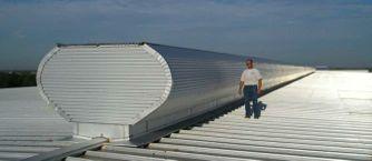

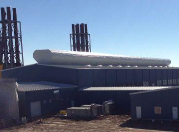


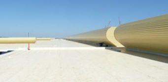
11 MoffittVent Pictures Page 11 of 12
12 MoffittVent Guide Specification 1.1. DESCRIPTION Furnish and Install MoffittVent and accessories as indicated on drawings QUALITY ASSURANCE MOFFITT (Jacksonville, FL, ) Products establish the standard of quality required. Manufacturer and erector shall demonstrate a minimum of five (5) years of related industry experience SUBSTITUTIONS No substitutions will be considered unless written request for approval has been submitted by the bidder and has been received by the designer at least ten (10) days prior to bid date. Any proposed substitutions should meet the standards set by the specification SUBMITTALS Furnish approval drawings (coordinated attachment points) prior to fabrication. Furnish erection package prior to shipment showing all erection procedures and accessories required for the specified product DESIGN MoffittVent shall be designed to withstand a windward load of psf and a psf snow load with structural frames located 10 on center standard or 8 on center if required for loading. Throat size shall be MATERIALS The MoffittVent free area shall increase proportionally throughout so as not to restrict calculated velocities with the exhaust opening not exceeding 1.5 times the throat size All ventilators shall be capable of self-cleaning by action of the elements, with provisions for carrying water and normal wind-transported soil to the outside of the ventilator Frames shall be constructed of minimum 3/16 ASTM A36 steel plate, angle and channel, and shall be shop welded. Component parts shall be sized for ease of shipment and handling, and be field assembled After fabrication, all structural components shall be hot dip galvanized. Sheeting shall be 22 gauge (Galvalume/G90 galvanized steel substrate: choose one) (note: for mill finish sheeting must be Galvalume) for the accelerator, hood, and end wall sheeting. The sheeting shall be (choose one): Mill finish Exterior stock Kynar color to match interior wash coat Exterior stock Kynar color to match interior Kynar color 2.3. ACCESSORIES Ventilators shall be equipped with 1/2 mesh, 19 gauge, galvanized bird screens attached to 3/8 diameter galvanized rod frames. Ventilators shall be equipped with dampers, each with a permanently sealed and lubricated mechanical gear reducer. The gear reducers shall open and close the dampers by means of rack arm and pinion gear operations. The damper shall be manually operated with a continuous loop chain wheel, manual roof hood crank, or electrically operated using ¼ or ¾ horsepower, 1800 RPM T.E.N.V. motors (choose one). Dampers shall be an integral part of the ventilator and shall form an inverted cone under the hood when the damper is in the open position for 5 sizes and above, and single leaf for sizes 4 and below INSPECTION Examine alignment of structural steel prior to installation and do not proceed until structure is within tolerances established by AISC INSTALLATION AND ERECTION Install MoffittVent and accessories in conformance with approved drawings and MOFFITT specifications & erection instructions DAMAGED MATERIAL Repair or replace all damaged material. Page 12 of 12