Florida s Flexible Filler Experience. Dr. Natassia Brenkus, The Ohio State University
|
|
|
- Shawn Robbins
- 5 years ago
- Views:
Transcription


1 Florida s Flexible Filler Experience Dr. Natassia Brenkus, The Ohio State University
2 Motivation Cost-effective method of bridge construction Prestressed Concrete Durability Issues Poor grouting practice Poor material performance Structural implications Reevaluation of current design specifications Flexible Fillers 2


3 Issues with grout Soft Grout Tendon Corrosion Tendon Failure 3


4 Post-tensioning Components Grout Flexible Filler Wax/Grease Internal Tendons designed as bonded. External Tendons designed as unbonded. All tendons unbonded. 4


5 Internal and External Tendons Drop-in Girders Internal Tendons Segmental Box Girders External Tendons 5
6 Research Status - Final Report Complete Literature review Filler injection Structural testing Flexural strength Fatigue at deviator and anchorage Wire break detection 6
7 Tasks Completed Literature review Filler injection Structural testing Flexural strength Fatigue at deviator and anchorage Wire break detection 7


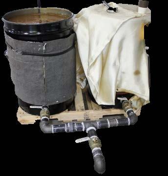

8 Developed Injection Procedures Vacuum assist Verified process outlet inlet 8
9 Tasks Completed Literature review Filler injection Structural testing Flexural strength Fatigue at deviator and anchorage Wire break detection 9
 Internal Tendon Specimens (2) External Tendon Specimens 10")
10 Structural Testing Internal and External Tendons Drop-in Girders Internal Tendons Segmental Box Girders External Tendons (3) Internal Tendon Specimens (2) External Tendon Specimens 10


11 Test Specimens 11
12 Flexural Testing 12
13 Design Specifications: AASHTO-LRFD 2017 Bonded Tendons Article For rectangular or flanged sections subjected to flexure about one axis where the approximate stress distribution specified in Article is used and for which f pe is not less than 0.5 f pu, the average stress in prestressing steel, f ps, may be taken as: ff pppp = ff pppp 1 kk cc dd pp Unbonded Tendons Article For rectangular or flanged sections subjected to flexure about one axis and for biaxial flexure with axial load as specified in Article , where the approximate stress distribution specified in Article is used, the average stress in unbonded prestressing steel may be taken as: ff pppp = ff pppp dd pp cc ll ee Mixed Reinforcement Conditions Article A Detailed Analysis B Simplified Analysis 13
14 Comparison with AASHTO-LRFD Using LRFD b simplified analysis for elements with bonded and unbonded tendons 1.4 Internal External IGS IWS IWC EWS EWC 14

15 Research Status Literature review Filler injection Structural testing Flexural strength Fatigue at deviator and anchorage Wire break detection 15

16 External Tendons Deviation Points Effects of fatigue Diabolos 16

17 Reduced Beam Testing 18 deg. Fretting fatigue Duct damage Anchor fatigue 11 deg. 17
18 Test Design Modeled fatigue test after ETAG-013 Minimum stress range of 11.6 ksi Maximum load of 65% of tensile element characteristic strength Minute Displacement Diabolo Strands Duct Strand Contact Pressure 18

19 Post-cycling evaluation Visual inspection of HDPE sections in diabolo Visual inspection of prestressing strand at wedges Ultimate tension tests of individual prestressing strands with diabolo in gage length 19


20 HDPE Sections Thickness (in.) Thickness (in.) HDPE Pipe Thickness Original Thickness Diabolo Location (in.) 0.16 Groove Depth Original Thickness Diabolo Location (in.) North: South: North: Live End South: Dead End 18 deg. 11 deg. 20


21 Anchorage Wedge bite marks 1.60" 0.28" 1.07" 0.25" 0.10" 21


22 Tension Tests diabolo Source: instron.com 22


23 Tension Tests 120% 100% 80% %GUTS 60% 40% 20% 0% 18 degree 11 degree Source: instron.com Strand sample 23

24 Channel 5 segmental bridge Tendon force difference at deviator 24
25 Outcomes and Implementation Injection procedures Developed heat transfer model for use in evaluating maximum length of tendon to inject Developed and delivered flexible filler training for engineers, contractors, and owners Evaluated AASHTO LRFD provisions for flexural design Evaluated fatigue resistance Evaluated diabolo geometry Developed prestressing strand breakage detection algorithm 25


26 Current Research Develop design guidelines and analysis procedures for bridge members with unbonded tendons with particular focus on a combination of unbonded tendons and bonded prestress and/or mild reinforcement. 26
27 Phases of Project Development of analytical modeling procedures Preliminary analytical study Experimental testing Integration of experimental and analytical data Development of design and analysis guidelines 27
28 Contact Information Dr. Natassia Brenkus, The Ohio State University /


29 Acknowledgements Marcus H. Ansley Structures Research Center CTL Labs and Dr. Gary Gan 29